ZARM Bremen Drop Tower Facility
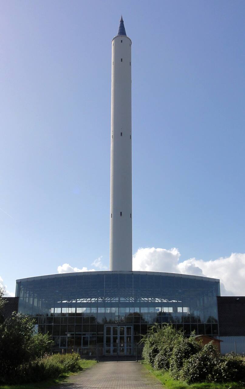
Jurgen Howaldt, licensed CC BY-SA, via Wikimedia Commons.
Testing a manipulator, a separation mechanism or an instrument meant to work in free fall against Earth’s own gravity means removing that gravity somewhere on the ground, and no single ground method removes it for long, cleanly and cheaply at once. A NASA survey of the alternatives lines them up by that trade: a small drag-shielded tower buys 2.2 s at package sizes to 125 kg, a deep evacuated shaft buys 5.18 s at about 10^-6 g but only one or two drops a day, and an aircraft flying parabolas buys tens of seconds but at gravity quality two orders of magnitude worse than either tower [5]. The aircraft option was formalized at NASA Lewis as the DC-9 program: about 1e-2 g for 18 to 22 s per parabola, tens of parabolas a flight, or 1e-3 g for a few seconds free-floated, with the ceiling set by g-jitter from atmospheric disturbance, piloting and airframe vibration rather than by any hardware limit [7]. A design study for a crewed microgravity technology laboratory draws the same trade from the researcher’s side: what a facility can offer is traded against iteration rate, modularity and how much of the apparatus can be operated remotely, and a ground rig that a team can rebuild and refly in an afternoon is worth more to a maturing technology than one that offers better gravity but a slower cycle [9]. ZARM Bremen sits at one corner of that trade: the deepest and slowest end, at the price of throughput, unless the campaign is run on the site’s second machine instead. One building at Am Fallturm 2 holds both weightlessness machines and the hall that feeds them: the 146 m drop tower gives 4.7 s of free fall at about 10^-6 g in a 120 m evacuated tube, or 9.3 s in catapult mode, and the GraviTower Bremen Pro standing beside it in the integration hall gives up to 2.5 s at about 10^-4 g but 20 times an hour, the only ZARM machine that produces sustained lunar and martian gravity [1]. The constraints that come with those microgravity figures govern what can fly: a 100 g structural design case in the tube, no damping elements, no cantilevers in catapult mode, and a standing instruction that mass must not move inside the capsule during the flight. Both fly the same Standard Capsule, are booked through the same operating company, and are supported by the same two assigned engineers, so an experiment can move between them without being rebuilt.
ZARM has existed since 1985, with ground broken for the tower in May 1988, the catapult cellar already allowed for, the tower inaugurated in September 1990, and the catapult, designed by ZARM engineers, following in December 2004 [1]. The GraviTower has been in service since the beginning of 2022, and its partial-gravity mode entered the operator’s user guide only in version 1.5 of 8 July 2024, revised in version 1.6 of 22 April 2025, so that capability is still being extended. No total floor area is published for the site; ZARM also operates thermal vacuum and vibration laboratories and a 12.5 m, 30 g centrifuge, which are separate facilities and are not covered here [3].
Laboratory data
Section titled “Laboratory data”| Parameter | Value |
|---|---|
| Operator | ZARM Fallturm-Betriebsgesellschaft mbH, University of Bremen |
| Location | Am Fallturm 2, 28359 Bremen, Germany |
| Commissioned | Tower 1990; catapult 2004; GraviTower 2022 |
| Type | Evacuated drop tube and driven partial-gravity tower |
| Floor area | Not published |
| Capabilities | Drop tower, GraviTower, Capsules, Hall |
| Simulant or terrain | Not applicable; sealed capsules only |
| Instrumentation | Standard Capsule Equipment, NI PXI, 1 kHz logging |
| Ground truth | ASC 7.050LN.075 IMU, plus or minus 50 g, mandatory |
| Fidelity limits | Own 10^-6 g figure not verifiable by the standard IMU |
| Access | ZARM FAB mbH, worldwide, 5 working days on site |
| Cited by | No robot entry; one accelerometer campaign [2] |
Capabilities
Section titled “Capabilities”Drop tower
Section titled “Drop tower”| Parameter | Value |
|---|---|
| Working volume | Tube 120 m by 3.5 m, 110 m of fall; capsule payload 1017 mm high |
| Test article limits | Capsule 500 kg in drop, 400 kg by catapult |
| Vacuum | 10 Pa; 18 pumps clear 1700 m3 of air in 1.5 to 2 h |
| Temperature | Not controlled; optional -20 to +60 C liquid circuit |
| Illumination | Not applicable; sealed capsule in an evacuated tube |
| Slope | Not applicable; payload center of gravity on the vertical axis |
| Gravity offload | Free fall, order 10^-6 g; 4.7 s drop, 9.3 s catapult |
| Instrumentation | Up to 6 Phantom Miro C321, 1920 x 1080 at 1480 fps |
Drop and catapult are two operating modes of one rig, not two rigs: the tower is a 146 m concrete shell 8 m in diameter around a 120 m steel tube of 3.5 m diameter, with about 600 steps to the top, and the 110 m fall ends in a container holding 15 m3 of polystyrene pellets to a depth of 8.2 m [1]. In drop mode the capsule is released at the top and falls for 4.7 s; in catapult mode a pneumatically driven, hydraulically controlled launcher in the cellar throws the same capsule up the tube at 168 km/h after a 0.25 s acceleration, so the free-fall time doubles to 9.3 s, with the acceleration force computed for each experiment so that the capsule arrives as close as possible to the top of the tube. An independent user describes it as an “8 meters high braking tank filled with fine graded polystyrol” [2], and notes that residual drag behaves differently in the two modes [2].
The tube is held at 10 Pa, about 0.075 torr, by eighteen pumps that remove 1700 m3 of air in 1.5 to 2 hours and is reflooded with air after every flight, so the pumpdown recurs each time and sets the cadence: up to three flights per working day, each cycle four hours from handover to hand-back, with handover slots at 08:00, 12:00 and 16:00 [2]. The tube is not a thermal facility, either: capsule temperature is nominally room temperature but shifts by a few kelvin seasonally, falling in winter to a few degrees Celsius inside the tube at 120 m, and an optional closed-loop glycol and water circuit runs -20 to +60 C with 2 kW of heating and 2.3 kW of cooling at +20 C, disconnected about 1 minute before a drop and about 10 minutes before a catapult launch.
Mass limits differ by mode and capsule: payload mass is 225 kg with the Standard Capsule, 265 kg with the Long Drop Capsule, and 165 kg by catapult [1]. Catapult operation adds a balancing requirement that has no equivalent in drop mode: the capsule center of gravity must sit inside a 1 mm diameter circle about the vertical geometric center line, taring takes about four hours and is done by ZARM staff after the qualification review, and any disassembly and reassembly during a campaign must leave the center of gravity inside that circle or the capsule is rebalanced. Mechanically weak experiments that cannot be reinforced on site, and liquid-electrolyte batteries, are refused [2].
GraviTower Bremen Pro
Section titled “GraviTower Bremen Pro”
| Parameter | Value |
|---|---|
| Working volume | 16 m tower; Standard Capsule envelope, 1017 mm high |
| Test article limits | Capsule 500 kg, payload 265 kg; 5 g design case |
| Temperature | Not controlled; optional -20 to +60 C liquid circuit |
| Gravity offload | 10^-4 g to 2.5 s; lunar 2.5 s, martian 3.0 s at 10^-2 g |
| Instrumentation | Li-Fi telemetry to 250 Mbit/s; Phantom Miro C321 |
The GraviTower trades microgravity quality for repetition rate: it gives up to 2.5 s at the order of 10^-4 g, two orders of magnitude coarser than the tube, but it does it 20 times an hour instead of three times a day, the capsule opened in about ten seconds between runs so that power, fluids or components can be exchanged, and booked as a GraviTower half-day, “the minimal counting unit”, where four hours of use counts as one flight starting at handover at 08:00 or 12:00 and “it does not matter how many actual runs would have been realized in total” [1]. Against the tower’s four-hour flight cycle, that repetition rate is what makes parameter sweeps and statistical campaigns possible.
The machine is a winch, a rail and a shield: a commercial hydraulic winch system of more than 4000 hp drives a rail-guided slider up and down a 16 m tower, and the slider encloses the experiment capsule and acts as its drag shield, which is what removes the need for an evacuated tube [1]. It is also the only ZARM machine that produces sustained partial gravity, giving lunar conditions up to 2.5 s and martian conditions up to 3.0 s at a quality the operators describe as of the order of 10^-2 g and explicitly as preliminary. In microgravity mode the Release-Caging-Mechanism, developed and patented by ZARM, decouples the capsule inside the moving slider and recouples it at the end of the run; the operators describe it as capable of controlling heavy payloads “in a very smooth and precise manner”. Partial gravity instead runs with the capsule mechanically connected to the slider, without the Release-Caging-Mechanism, and drive vibration is the reason the number is what it is; see below.
The profile is a user parameter rather than a fixed characteristic: amplitudes of the acceleration and deceleration profile are set through a graphical interface up to 5 g in total, and the system computes the microgravity duration that results, so a gentler profile buys a shorter weightless window [1]. The structural design case is far gentler than the tower’s: “In GraviTower operation, max. accelerations of only about 5 g in total occur. Thus, exclusively GraviTower payloads may adapt to that level”. A simplified Matlab or Python trajectory script can be supplied before a campaign so that the kinematics can be checked against the payload’s own limits. Switching between microgravity and partial-gravity mode takes about one day.
The optional thermal liquid circuit is available through the capsule docking system but must be disconnected before each launch command and is reconnected immediately after each run. Operation is from a dedicated control desk beside the tower rather than the drop tower control room.
Capsules
Section titled “Capsules”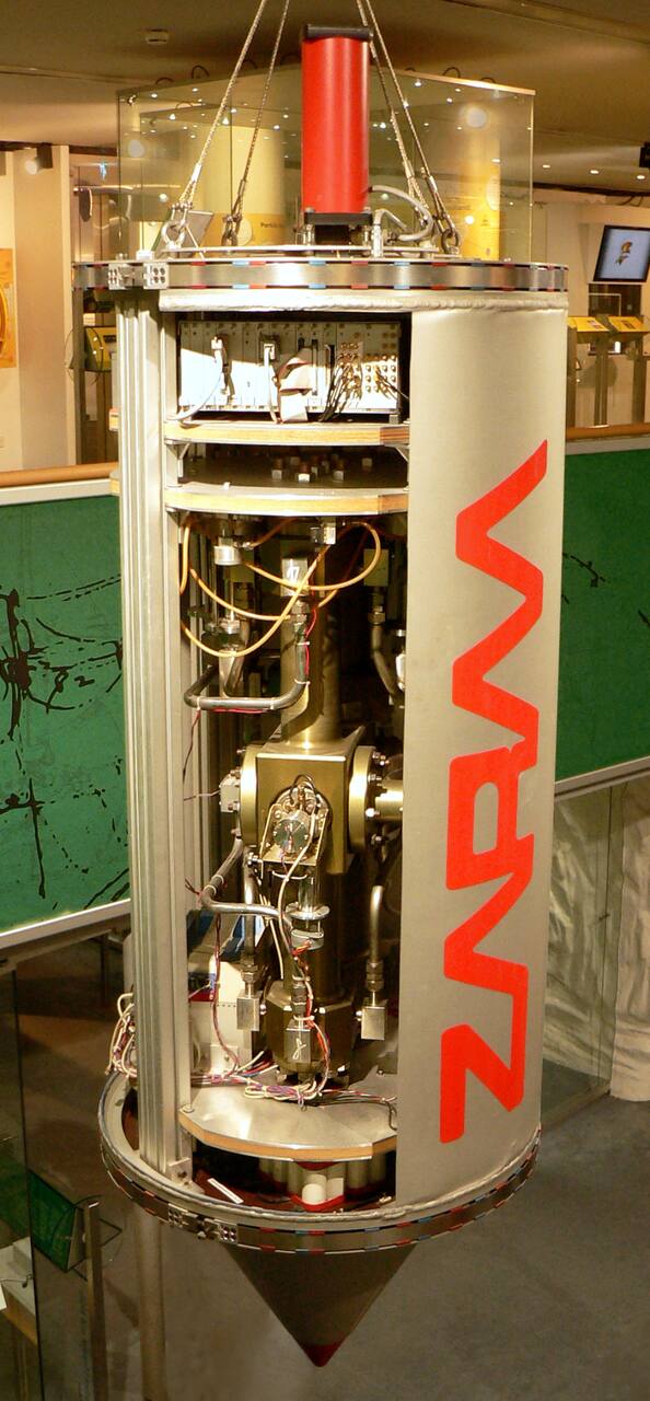
Axel Hindemith, via Wikimedia Commons. Licensed CC BY-SA.
| Parameter | Value |
|---|---|
| Working volume | Standard Capsule 1017 mm high; Long Drop Capsule 1780 mm |
| Test article limits | 100 kg per platform including the platform; 50 kg point load |
| Instrumentation | NI PXI, 40 analog inputs at 16 bit, 1 kHz TDMS logging |
| Ground truth | ASC 7.050LN.075, plus or minus 75 deg/s and plus or minus 50 g |
The capsule is the piece the two towers share: the same experiment can be flown in drop, catapult or GraviTower mode without rebuilding, with a payload envelope 1017 mm high in the Standard Capsule, 599 mm in diameter between the stringers and 700 mm wide off them, on a platform area of 0.359 m2, each platform carrying at most 100 kg including its own 15 kg with a point load limit of 50 kg at the center and mass distributed evenly [1]. The Long Drop Capsule raises that height to 1780 mm but is available in drop mode only, and the capsule interior itself is a sealed vessel at about 1013 hPa, with a specified pressure loss below 1 percent in 3 hours and an operational band of 980 to 1300 hPa outside which the run is aborted. The operators state that “all dimension limitations are hard limits”, and capsule internal pressure is monitored continuously as housekeeping.
Integration is on ZARM’s own aluminum, plywood and aluminum sandwich platforms. Drilling holes and threads is permitted; opening the outer contour is not, and machining is done only after consulting the drop tower engineers.
Integration hall
Section titled “Integration hall”| Parameter | Value |
|---|---|
| Test article limits | ZARM platforms, aluminum and plywood sandwich |
The hall at the foot of the tower is where capsules are built up, qualified and, since the GraviTower’s commissioning, flown: the GraviTower stands inside it, unpressurized and in room air. Users must arrive at least five working days before the first flight for integration, ground testing and qualification, and a risk assessment by the experimenter is mandatory before work starts. No dimensions, crane capacity or cleanliness class is published for the hall.
Compared to other ground facilities
Section titled “Compared to other ground facilities”The Bremen tower is not the only ground option, and it is not the deepest one. NASA’s Lewis Research Center (now Glenn) operated a 5.18 s, 132 m evacuated shaft at about 10^-6 g, the same order as Bremen’s tube but with a shorter fall and, at 65 g over 0.15 s in a decelerator cart, a harder landing than Bremen’s roughly 50 g case [6]. The same center’s 2.2 Second Drop Tower and the Marshall Space Flight Center’s 100 m tower sit at the shallow end of the same family, trading duration for a simpler drag-shielded rig and a same-day turnaround [5]. None of the drop towers approach aircraft duration: the NASA Lewis DC-9 gave 18 to 22 s per parabola, forty-odd parabolas a flight, at a gravity quality two orders of magnitude coarser than any tower and set by airframe jitter rather than a physical floor [7]. Bremen’s own answer to that duration gap is not an aircraft but the catapult, which roughly doubles the tube’s free fall without leaving the ground.
What a facility is asked to reproduce also differs by where the disturbance actually comes from. A catalog of on-orbit microgravity disturbances measured on Spacelab, Mir and the shuttle middeck finds crew exercise, pump activations, latch motions and thruster firings all injecting transients from a few micro-g to tens of milli-g superimposed on a quasi-steady drag floor, none of which a sealed falling capsule or a parabola-flying aircraft reproduces [8]. A drop tower, a centrifuge and a parabolic aircraft each remove or add gravity by a different mechanism, so a result qualified on one does not stand in for a result on another: a penetrometry campaign validated for the MMX sampler was flown on parabolic aircraft rather than in a drop tower specifically because the several-second contact events it measured needed sustained low gravity with the operator able to intervene between shots, not a single few-second fall [10].
Other ways to remove or reduce gravity
Section titled “Other ways to remove or reduce gravity”Free fall is one of four families that robotics programs use, and the others answer different questions. Parabolic aircraft carry a rover wheel or sampler through lunar-gravity parabolas of 20 to 30 s [11] with soil and hardware both at reduced gravity. Two campaigns on a Falcon 20 found that matching only the wheel load in 1 g overstated lunar mobility, with drawbar pull to weight down 20 percent or more and sinkage up to 40 percent, while granular scaling laws came within 8.5 percent on drawbar pull; soil was prepared at 1 g between parabolas, so the density is not one formed in reduced gravity [11]. A NASA consolidation of mobility test practice records the same doubt about cone index gradient as a way to reproduce lunar soil strength and states that no known facility reproduces the inertial and dynamic effects of reduced gravity on a full vehicle; it is a set of recommendations with no new measurements [13]. A sealed capsule falling for 4.7 s cannot carry a wheel-soil test of that kind, because the soil would have to settle and the wheel reach steady state inside the window.
Suspension and pneumatic offload hold part of the weight on a rig that stays on the ground and runs for as long as the test needs. The JSC Pogo pneumatic actuator held commanded lifting force to within 2.2 to 10 percent across 16 subject, gravity and speed combinations at 1/6 g and 3/8 g, and the error grew with the dynamic content of the motion; the study used four subjects at one facility [15]. The ARGOS cable system at NASA is characterized by where the gimbal pivot sits relative to the suit center of gravity: functional settings fell 2.5 to 6.4 cm above and 1.3 to 2.5 cm aft of the modeled center, from 14 subjects and 68 configurations, with no residual force or bandwidth figure for the rig [12]. DLR’s Landing and Mobility Test Facility hung the Philae landing gear from a robot arm through an offloading suspension and recorded a tilt limiter that allowed at least 9 degrees against a design of 3 degrees; the suspension’s own offload accuracy was not measured [17]. Offload rigs give time and a full-scale article, and each leaves a force or friction residual that a tower of 10^-6 g does not have.
Flight is the remaining family and the reference for the others. Astrobee has flown on the ISS for six years, with more than 165 real-time operations and more than 90 Guest Science sessions, and its localization error is scored against ground truth from the authors’ own mapping pipeline rather than independent metrology [14]. Its predecessor SPHERES was characterized on the ground on a thrust balance, where a thruster delivered 0.1783 N at 55 psig against 0.2480 N predicted and six simultaneous thrusters each lost over 30 percent of thrust; those corrections were never tested on flight hardware [16]. Bench and tower characterization of this kind brackets what the flight system will do and does not replace the flight record.
Instrumentation
Section titled “Instrumentation”The Standard Capsule Equipment is mandatory and is supplied and programmed by the facility, not by the user, a National Instruments PXI real-time system whose sequence is written in LabVIEW by the assigned ZARM engineer to the experimenter’s specification. It carries 40 differential analog inputs at 16 bit and 100 Hz to 10 kHz, 10 analog outputs, 8 RS-485 or RS-422 lines and one RS-232, 48 isolated digital inputs and 64 digital outputs, and every channel is logged at a common 1 kHz into per-minute TDMS files exportable to ASCII so a campaign’s data arrives on a single time base [1]. Power inside the capsule is 24 V from two 25 Ah lead-acid packs, capped at 15 A per line and 1500 W total across eight switchable lines, and a high-sensitivity inertial measurement unit, an ASC 7.050LN.075 with a 3-axis gyro to plus or minus 75 degrees per second and a 3-axis accelerometer to plus or minus 50 g, is mandatory in every capsule and logged on the capsule control system. The published GraviTower microgravity profile was measured with an iIMU-FCR-03 and the partial-gravity profiles with an ASC 4311LN [1]. External power, coolant and battery charging are all disconnected before the run. The standard capsule sensor set also reads ambient light, 0 to 1000 lux to plus or minus 50 lux, and illumination hardware is supplied as an integration service [3]. A separate Drop Tower Sensor Pack logs the internal capsule environment for the operators and can be released to the experimenter on request.
High-speed imaging is available at facility level. Six Phantom Miro C321 cameras give 1920 x 1080 at 1480 frames per second for 4.48 s, or 94,510 frames per second at 640 x 8 for 28.4 s, with 240 GB of internal memory and a 1 us minimum exposure [1]. Up to three Photron FASTCAM MC2 units give 512 x 512 at 2000 frames per second, and their live video can be relayed from the falling capsule by an infrared optical link at the top of the tube. The operators recommend switching the Phantom’s cooling fan off during a run to avoid disturbing the microgravity, and single the Phantom out for GraviTower work because its large local memory holds several recordings across successive runs without a download between them [3].
Telemetry differs between the two machines. The tower uses WLAN at up to 450 Mbit/s down the tube, with live remote control throughout the flight; inside a metal slider that will not work, so the GraviTower uses an industrial Li-Fi optical wireless link at up to 250 Mbit/s, with the capsule radio unit relocated to the top of the capsule structure [3].
Access is open to external users worldwide through ZARM FAB mbH, with two assigned drop tower engineers, one mechanical and one electrical, through preparation, integration and campaign. The operators state that lead time “varies from experiment to experiment”, with examples “with only days or a few weeks on the one hand and several months or even years on the other” [3]. No prices are published.
What it does not reproduce
Section titled “What it does not reproduce”Its own quoted microgravity level, as measured by its own standard instrument. The mandatory inertial unit (see the ground truth and fidelity limits in the table above) is not sensitive enough to confirm it, and the operators say plainly that proving the figure requires high-sensitivity accelerometers that are not standard equipment, pointing users to the MICROSCOPE literature for the measurement.
A constant residual acceleration. The 10 Pa tube pressure exists to hold residual drag down, and an independent user quantifies what it holds it to: 10 Pa “minimize[s] the drag effect at 200 um s^-2” [2], about 2 x 10^-5 g. The time behavior differs by mode: “in a standard drop, the drag due to the residual air in the tower is continuously increasing from the time of the capsule release to the end of the drop. During a catapult shot the drag decreases to zero at the apex of the trajectory i.e. at the very precise moment when the velocity is also zero” [2]. A drop degrades monotonically; a catapult shot is best in the middle and worst at both ends.
A gentle landing. Each payload must withstand deceleration peaks of about 50 g, and about 30 g of initial acceleration in catapult mode, treated as quasi-steady, with a factor of two recommended on top: “all capsule payloads shall be able to withstand accelerations of about 100 g (100 % safety margin included) in drop tower operation, at least” [1]. The GraviTower is the exception, at about 5 g in total, and the operators warn that a payload built to that level is a GraviTower payload only. This is the constraint that governs whether a robotic mechanism can fly in the tube at all. Independent measurement puts the deceleration at about 0.2 s and not exceeding 400 m s^-2 [2].
Compliance. The operators state that shock absorbers within the experimental setup “shall be avoided”, that industrial shock absorbers “might lead to an amplification of accelerations as they delay damping of the payload”, and that “the damping of a payload will be the best, the more rigid it is connected to the capsule platform”. For catapult operation, “cantilever beams or any kind of systems that might oscillate during the capsule acceleration phase must be avoided”. A deployable boom, a compliant arm or a suspension cannot be flown in its operational configuration.
Motion of the article during the run. This is the direct limit on robotics testing: “change of motion of masses during free fall shall be avoided. If this cannot be achieved, accelerations must be compensated by accelerating counterweights on or around the identical axis. Please consider the fact that you do not know about the exact location of the COG of the complete capsule in no direction” [1]. A manipulator or a mobility actuation exercised during the 4.7 s either carries a counterweight or degrades the microgravity it is being tested in. The requirement is written jointly for both machines, and thruster effects “must be avoided in the GraviTower as well”.
Thrust or venting. The vent line valve at the capsule lid must be closed before release or launch and all gases stored in onboard containers; “a pressure release is not valid during free fall”. In the GraviTower, gases are stored onboard and vented between runs.
Partial gravity uncoupled from the drive. This is the GraviTower’s own stated principal limit. Partial gravity is “only possible without the advantage of the RCM, since a mechanical connection of experiment and slider is required in the current development stage. This reduces the quality of the targeted acceleration level to the order of 10^-2 g, depending on the input kinematics and the experiment mass”, and vibration of the drive “might couple into the experiment” [1]. An article’s own mass is therefore a term in the accuracy of the gravity level it is tested at. No vibration spectrum is published. The microgravity figure is hedged the same way, resting on “preliminary measurements of the residual acceleration… during several dedicated test runs” at “the current stage of development of the GraviTower”. A campaign whose result depends on the residual acceleration floor belongs in the tube.
Gravity levels other than lunar and martian. Those two are what exists; further levels await additional test campaigns, and specific levels can be prepared on request for a dedicated campaign.
Both GraviTower modes in one campaign without a gap. The operators state: “Switching between microgravity and partial-gravity operation mode takes approximately one day. Thus, a break in the campaign must be considered if both operation modes are requested”.
Run-to-run identity in catapult mode. The free-fall duration is not fixed [1]: “Single periods of microgravity may vary some milliseconds from flight to flight in the catapult mode (up to 9.3 s). It depends on the actual pneumatic pressure that is applied for the specific capsule launch”.
The rotation a separating body leaves with. The MASCOT separation mechanism was qualified here and then flown to asteroid Ryugu, and the two halves of that pairing agree on one axis and not the other. Time to clear the support frame, a frame about 20 cm long internally, came out at 3.9 ± 1.2 s in the tower against 3.1 s from flight dynamics and 3.2 ± 1 s from the lander’s magnetometer: agreement, within the test scatter [4]. Rotation did not agree. The flight rotation period was 138.9 to 139.2 s, measured to ±1 s by MasMag, while the drop tower article spun with an 84.4 s period and almost purely about x [4]. A separation qualification in this tower bounds the clearing time and says nothing about the attitude the released body arrives in.
Vacuum, dust, terrain or thermal flux at the article. The article sits inside a sealed capsule at one atmosphere; the tube vacuum is not its environment unless the experiment brings its own vacuum vessel and evacuates it through the capsule vent line, and ZARM operates separate thermal vacuum and vibration laboratories and a 12.5 m, 30 g centrifuge for that work [3].
Campaigns run there
Section titled “Campaigns run there”MICROSCOPE T-SAGE electrostatic accelerometer qualification, to June 2014. Twenty-five campaigns and 71 falls, 49 drops in free-flyer configuration and 22 by catapult, to assess the dynamic behavior of the twelve digital servo loops of the MICROSCOPE differential accelerometer; the flight models themselves were dropped only 8 times to limit the stress [2]. The capsule was 2 m high, 80 cm in diameter and about 300 kg with electronics and data acquisition, with a 50 cm cone at the bottom to stabilize it during deceleration, and the instrument axes were arranged so that the residual drag was measured along the vertical [2].
What the campaign established is also a statement of the facility’s limits. The drops are described as “the only way to test the servo control dynamics”, but the electronics had to be run at 100 V instead of 48 V, and the test mass bias raised from 41.4 V to 89.2 V, to generate enough electrostatic force to acquire the test masses inside the short free-fall window [2]. That widened the X full-scale range to 2.7 x 10^-5 m s^-2 against 1.6 x 10^-6 m s^-2 in the flight high-resolution mode, and the authors conclude that “since the instrument is configured in a coarse acquisition mode because of the short free fall time, its ultimate performances are out of reach” [2]. The catapult apex was used to estimate instrument bias, but the authors record that “this determination is not precise because the test-masses are not yet controlled along and about all directions”. Control loop dynamics can be qualified here; end-to-end sensitivity cannot.
MASCOT separation mechanism qualification, for Hayabusa2. The mechanism that pushed the MASCOT lander off Hayabusa2 above Ryugu was developed and qualified by dropping it here, across at least three drop test campaigns. The tower is where the mechanism’s release velocity was measured at all: optical tracking of the lander leaving the support frame gave 4.79 ± 1.69 cm/s (3 sigma) on the test article, scaled to 4.94 ± 1.7 cm/s predicted for the flight model after correcting for the flight spring rate, 0.21 against 0.19 N/mm, and the flight mass, 9.66 against 9.29 kg [4]. Flight gave 6.1 cm/s from flight dynamics, 5.9 cm/s from ONC image analysis and 6.0 ± 1.5 cm/s from the magnetometer, so the prediction was low, though the flight figures sit inside the test article’s own 3 sigma band.
Two facility-specific results came out of the same campaigns. Flight-to-flight scatter in eject velocity fell from 5.5 to 1.9 cm/s once the push-off plate tips were padded to force three-point contact, the original scatter being caused by manufacturing tolerances on hand-made CFRP parts changing the contact area [4]. And the residual scatter that remained is attributed to the tower setup rather than to the mechanism: the push-off spring preload could only be adjusted to 250 ± 50 N per flight, which is what moved release velocity over 4.26 to 5.25 cm/s between shots. A drop tower campaign measures the article and the rig together.
Other space robotics. The operators state generally that users “perform technology tests preparing and qualifying instruments for future space missions”, and offer the facility for that purpose [3]. Beyond the MASCOT mechanism above, no campaign involving a manipulator, rover, sampler or free-flying robot at this facility is published.
GraviTower. No GraviTower campaign is published. The operators describe the intended use generically, “to test preliminary setups or experiment components, to qualify new technologies for space and / or exploration missions, or to facilitate dedicated microgravity and partial-gravity research with a very high repetition rate”, but name no user or result.
What is not established
Section titled “What is not established”No campaign at this facility with a manipulator, rover, sampler or free-flying robot is published in the held record, so the 4.7 s window and the rule against moving masses have not been tested against a robotic payload here [3]. The MASCOT qualification bounded clearing time and release velocity, and the rotation of the test article differed from flight [4]. The microgravity level of the tube rests on the operator’s figure, which the standard instrument cannot verify, and the GraviTower figures are stated as preliminary [1]. Independent measurements of the GraviTower, a drive vibration spectrum, floor area and hall dimensions are not in the held sources. The comparison with aircraft and offload methods rests on a 1989 survey and on single-facility studies with small samples [5][11][15]. The corpus does not hold further curated sources on drop towers, GraviTower operation or robotic payloads in free fall; the remaining works under this topic concern thermal vacuum, radiation, soil-bin and wheel testing and are not cited here.
References
- Könemann, T. and Cornelius, M. (2024). Bremen Drop Tower: Payload User's Guide, Version 1.6
. ZARM Fallturm-Betriebsgesellschaft mbH, University of Bremen. Source
BibTeX
@techreport{konemann2024bremen, title = {Bremen Drop Tower: Payload User's Guide, Version 1.6}, author = {Könemann, Thorben and Cornelius, Merle}, institution = {ZARM Fallturm-Betriebsgesellschaft mbH, University of Bremen}, year = {2024}, url = {https://www.zarm.uni-bremen.de/fileadmin/user_upload/Research/Testing_and_Facilities/ZARM_BDT_PUG.pdf} } - Liorzou, F., Touboul, P., Rodrigues, M., Chhun, R., Foulon, B., Guidotti, P.-Y., Hardy, É., Huynh, P.-A., Lebat, V., Boulanger, D., Christophe, B., Métris, G., Robert, A., Selig, H. and Lämmerzahl, C. (2022). MICROSCOPE instrument description and validation
. Classical and Quantum Gravity, 20. Source
BibTeX
@article{liorzou2022microscope, title = {{MICROSCOPE} instrument description and validation}, author = {Liorzou, Françoise and Touboul, Pierre and Rodrigues, Manuel and Chhun, Ratana and Foulon, Bernard and Guidotti, Pierre-Yves and Hardy, Émilie and Huynh, Phuong-Anh and Lebat, Vincent and Boulanger, Damien and Christophe, Bruno and Métris, Gilles and Robert, Alain and Selig, Hanns and Lämmerzahl, Claus}, journal = {Classical and Quantum Gravity}, volume = {39}, number = {20}, pages = {204002}, year = {2022}, doi = {10.1088/1361-6382/ac1619}, abstract = {Abstract This paper focuses on the dedicated accelerometers developed for the MICROSCOPE mission taking into account the specific range of acceleration to be measured on board the satellite. Considering one micro-g and even less as the full range of the instrument with an objective of one femto-g resolution, that leads to a customized concept and a high-performance electronics for the sensing and servo-actuations of the accelerometer test-masses. This range and performance directed the payload development plan. In addition to a very accurate geometrical sensor core, a high performance electronics architecture provides the measurement of the weak electrostatic forces and torques applied to the test-masses. A set of capacitive detectors delivers the position and the attitude of the test-mass with respect to a very steady gold-coated cage made in silica. The voltages applied on the electrodes surrounding each test-mass are finely controlled to generate the adequate electrical field and so the electrostatic pressures on the test-mass. This field maintains the test-mass motionless with respect to the instrument structure. Digital control laws are implemented in order to enable instrument operation flexibility and a weak position detector noise. These electronics provide both the scientific data for MICROSCOPE’s test of the weak equivalence principle and the input for the satellite drag-free and attitude control system.} } - (2026). ZARM: Labs and Test Facilities. zarm.uni-bremen.de/en/research/labs-and-test-facilities
BibTeX
@misc{zarmlabs, title = {ZARM: Labs and Test Facilities}, organization = {zarm.uni-bremen.de}, year = {2026}, url = {https://www.zarm.uni-bremen.de/en/research/labs-and-test-facilities} } - Grimm, C. D., Lange, C., Lange, M., Mierheim, O., Sasaki, K., Meyer, M., Kroth, W., Ulamec, S. and Ho, T.-M. (2020). The MASCOT Separation Mechanism: A Reliable, Low-Mass Deployment System for Nano-Spacecraft
. CEAS Space Journal, 3. Source
BibTeX
@article{grimm2020mascot, title = {The {MASCOT} Separation Mechanism: A Reliable, Low-Mass Deployment System for Nano-Spacecraft}, author = {Grimm, Christian D. and Lange, Caroline and Lange, Michael and Mierheim, Olaf and Sasaki, Kaname and Meyer, Michael and Kroth, Wolfgang and Ulamec, Stephan and Ho, Tra-Mi}, journal = {CEAS Space Journal}, volume = {12}, number = {3}, pages = {343--365}, year = {2020}, doi = {10.1007/s12567-020-00302-y}, abstract = {Abstract The Mobile Asteroid Surface Scout (MASCOT), an Asteroid Lander carried by the Hayabusa2 spacecraft, successfully landed on the Near-Earth Asteroid (162173) Ryugu on October 03, 2018. Thereby accomplishing the first-ever landing of a European spacecraft on the surface of this type of celestial body. MASCOT was a prototype design of a new class of nano-size surface science packages for the exploration of small solar system bodies. The very low gravity (thus, very low escape velocity) of the target body required the design of a miniaturized deployment mechanism with a relatively small, well-reproducible separation velocity. In addition, the mechanism also had to safely restrain the lander to the mother spacecraft during the launch and its 3.5-year cruise phase. In this paper, we describe in detail the design, numerical analysis and test of this newly developed separation mechanism. Furthermore, we compare the mechanism to other existing deployment systems and verify its performance with two independent analysis methods using actual flight data taken during the ultimate flight activation event, which initiated the successful delivery and surface operation of the MASCOT asteroid lander.} } - Lekan, J. (1989). Microgravity Research in NASA Ground-Based Facilities
. AIAA Aerospace Sciences Meeting, NASA TM-101397. Source
BibTeX
@inproceedings{lekan1989microgravity, title = {Microgravity Research in NASA Ground-Based Facilities}, author = {Lekan, Jack}, booktitle = {AIAA Aerospace Sciences Meeting}, number = {NASA TM-101397}, institution = {NASA Lewis Research Center}, year = {1989}, doi = {10.2514/6.1989-236}, abstract = {An overview of reduced gravity research performed in NASA ground-based facilities sponsored by the Microgravity Science and Applications Program of the NASA Office of Space Science and Applications is presented. A brief description and summary of the operations and capabilities of each of these facilities along with an overview of the historical usage of them is included. The goals and program elements of the Microgravity Science and Applications programs are described and the specific programs that utilize the low gravity facilities are identified. Results from two particular investigations in combustion (flame spread over solid fuels) and fluid physics (gas-liquid flows at microgravity conditions) are presented.} } - Thompson, D. M. (1999). Zero Gravity Research Facility User's Guide
. NASA Glenn Research Center, NASA/TM-1999-209641. Source
BibTeX
@techreport{thompson1999zerogravity, title = {Zero Gravity Research Facility User's Guide}, author = {Thompson, Dennis M.}, number = {NASA/TM-1999-209641}, institution = {NASA Glenn Research Center}, address = {Cleveland, Ohio}, year = {1999}, url = {https://ntrs.nasa.gov/citations/20000017932}, abstract = {The Zero Gravity Research Facility (ZGF) is operated by the Space Experiments Division of the NASA John H. Glenn Research Center (GRC) for investigators sponsored by the Microgravity Science and Applications Division of NASA Headquarters. This unique facility has been utilized by scientists and engineers for reduced gravity experimentation since 1966. The ZGF has provided fundamental scientific information, has been used as an important test facility in the space flight hardware design, development, and test process, and has also been a valuable source of data in the flight experiment definition process. The purpose of this document is to provide information and guidance to prospective researchers regarding the design, buildup, and testing of microgravity experiments.} } - Neumann, E. S., Withrow, J. P. and Yaniec, J. S. (1996). Users Guide for NASA Lewis Research Center DC-9 Reduced-Gravity Aircraft Program
. NASA, NASA-TM-106755. Source
BibTeX
@techreport{neumann1996users, title = {Users Guide for NASA Lewis Research Center DC-9 Reduced-Gravity Aircraft Program}, author = {Neumann, Eric S. and Withrow, James P. and Yaniec, John S.}, number = {NASA-TM-106755}, institution = {NASA}, year = {1996}, url = {https://ntrs.nasa.gov/citations/19970010375}, abstract = {The document provides guidelines and information for users of the DC-9 Reduced-Gravity Aircraft Program. It describes the facilities, requirements for test personnel, equipment design and installation, mission preparation, and in-flight procedures. Those who have used the KC-135 reduced-gravity aircraft will recognize that many of the procedures and guidelines are the same.} } - DeLombard, R., McPherson, K., Hrovat, K., Moskowitz, M., Rogers, M. J. B. and Reckart, T. (1997). Microgravity Environment Description Handbook
. NASA, NASA-TM-107486. Source
BibTeX
@techreport{delombard1997microgravity, title = {Microgravity Environment Description Handbook}, author = {DeLombard, Richard and McPherson, Kevin and Hrovat, Kenneth and Moskowitz, Milton and Rogers, Melissa J. B. and Reckart, Timothy}, number = {NASA-TM-107486}, institution = {NASA}, year = {1997}, url = {https://ntrs.nasa.gov/citations/19970022250}, abstract = {The Microgravity Measurement and Analysis Project (MMAP) at the NASA Lewis Research Center (LeRC) manages the Space Acceleration Measurement System (SAMS) and the Orbital Acceleration Research Experiment (OARE) instruments to measure the microgravity environment on orbiting space laboratories. These laboratories include the Spacelab payloads on the shuttle, the SPACEHAB module on the shuttle, the middeck area of the shuttle, and Russia's Mir space station. Experiments are performed in these laboratories to investigate scientific principles in the near-absence of gravity. The microgravity environment desired for most experiments would have zero acceleration across all frequency bands or a true weightless condition. This is not possible due to the nature of spaceflight where there are numerous factors which introduce accelerations to the environment. This handbook presents an overview of the major microgravity environment disturbances of these laboratories. These disturbances are characterized by their source (where known), their magnitude, frequency and duration, and their effect on the microgravity environment. Each disturbance is characterized on a single page for ease in understanding the effect of a particular disturbance. The handbook also contains a brief description of each laboratory.} } - Saenz-Otero, A. (2005). Design Principles for the Development of Space Technology Maturation Laboratories Aboard the International Space Station. Source
BibTeX
@phdthesis{saenzotero2005design, title = {Design Principles for the Development of Space Technology Maturation Laboratories Aboard the International Space Station}, author = {Saenz-Otero, Alvar}, school = {Massachusetts Institute of Technology}, type = {Ph.D. thesis}, year = {2005}, url = {https://dspace.mit.edu/handle/1721.1/33065} } - Smyth-Moore, A., Borg, J., Soria-Salinas, Á., Murdoch, N., Kato, H., Miyamoto, H., Usui, T., Kaufmann, E., Granvik, M. and Hagermann, A. (2025). Microgravity penetrometry flight campaign in support of MMX sampler science exploitation
. Progress in Earth and Planetary Science, 38. Source
BibTeX
@article{smythmoore2025microgravity, title = {Microgravity penetrometry flight campaign in support of MMX sampler science exploitation}, author = {Smyth-Moore, Alexander and Borg, Johan and Soria-Salinas, Álvaro and Murdoch, Naomi and Kato, Hiroki and Miyamoto, Hideaki and Usui, Tomohiro and Kaufmann, Erika and Granvik, Mikael and Hagermann, Axel}, journal = {Progress in Earth and Planetary Science}, volume = {12}, number = {38}, year = {2025}, doi = {10.1186/s40645-025-00704-8}, abstract = {Abstract Characterising the mechanical properties of minor bodies is essential for understanding their origin and evolution. Past missions such as Hayabusa2 have landed on asteroids to sample and discover what these bodies are made of. However, there has been conflicting evidence and reports into the physical properties of the granular surface material of these bodies. With future missions such as Japan Aerospace eXploration Agency’s Martian Moons eXploration mission landing on Phobos, the understanding and identification of these physical properties is crucial to maximising the scientific output from these missions. Penetrometry, the determination of the reaction force that an object experiences as it penetrates a surface, can help to understand the essential properties of regolith, such as grain size, porosity and cohesion. Results of penetrometry experiments are largely analysed based on empirical models, which presents us with a challenge if we want to apply them to understand granular materials on asteroid surfaces because gravity cannot be eliminated in the laboratory. Hence, it is essential to verify penetrometry as a method and validate penetrometry instrument designs in microgravity. For this purpose, we conducted a microgravity experiment onboard a parabolic flight campaign. Our experiment tested the use of penetrometry in asteroid-analogue environments by investigating samples with varying properties, such as grain size distribution and shape, and then compared to 1 g experiments to understand the role microgravity plays. The experiment provided a substantial database for future analysis. This paper will focus on the design of the experiment and the parabolic flight campaign in which the experiments were conducted. The design decisions and the variables adjusted during the experiment will be discussed, evaluating how these influenced the campaign and its outcomes. We will also provide a snapshot of preliminary results of the data captured during this experiment. For example, we show the effect of cohesion on penetrometer reaction force, with more cohesive materials providing larger reaction forces nearly of the same magnitude of their 1 g counterparts. We also show that penetrometer tip shapes provide different reaction forces and that flat tips provide the largest reaction force compared to the others. The influence of penetration velocity will be investigated further with the aid of theoretical models. Early indications from the results seen so far are promising for future analyses and will provide key information for the analysis of penetrometry data on future missions.} } - Daca, A. (2023). Predicting Planetary Rover Mobility in Reduced Gravity Using 1-g Experiments
. Unpublished. Source
BibTeX
@phdthesis{daca2023predicting, title = {Predicting Planetary Rover Mobility in Reduced Gravity Using 1-g Experiments}, author = {Daca, Adriana}, journal = {Unpublished}, school = {Concordia University}, address = {Montreal, Quebec, Canada}, type = {PhD thesis}, month = {February}, year = {2023}, doi = {10.13140/rg.2.2.12718.28485}, abstract = {Traversing granular regolith, especially in reduced gravity environments, remains a potential challenge for wheeled rovers. Mitigating hazards for planetary rovers requires testing in representative environments, but direct Earth-based testing fails to account for the effect of reduced gravity on the soil itself. Here, experimental apparatus and techniques for reduced-gravity flight testing are used to systematically evaluate three existing Earth-based testing methods and develop guidelines for their use and interpretation: (i) reduced-weight testing, (ii) matching soil testing instrument response through soil simulant design, and (iii) granular scaling laws (GSL). \nExperimentation campaigns flying reduced-gravity parabolas, with soil and wheel both in lunar-g, have shown reductions in net traction of 20% or more and increases in sinkage of up to 40% compared to Earth-based testing methods (i) and (ii). Scaled-wheel testing, according to GSL (method iii) has shown better agreement with reduced-g tests (less than 10% error) and also tends to err on the side of conservative predictions. \nLimitations of GSL are investigated including a recently proposed cohesion constraint (that the wheel radius ratio must be the inverse of the gravity ratio) and the effects of wheel size and aspect ratio on GSL’s accuracy. It was found that the cohesion constraint can most likely be ignored for mildly cohesive soils such as lunar regolith. Limits on wheel sizes and aspect ratio variation are also proposed. \nThe application of GSL to planetary rover testing is demonstrated through two studies undertaken in collaboration with NASA’s Jet Propulsion Laboratory. One study compares wheel designs for a skid-steer lunar rover in single-wheel tests scaled by GSL, demonstrating that diagonal grousers improve turning performance without requiring larger wheels. The second study involves application of GSL to the design of two reconfigurable test platforms for evaluating steep-terrain mobility performance. \nAnother aspect of rover mobility testing—normal force control in single-wheel testbeds—is also investigated. An improved method for single-wheel testing, using a 4-bar mechanism, essentially eliminates normal force oscillations from frictional vertical sliders. \nFinally, guidelines for conducting and interpreting 1-g mobility tests for lunar rovers are presented, and potential avenues for future research are outlined.} } - Jarvis, S. L., Vu, L. Q., Gupta, G., Benson, E., Kim, K. H., Rhodes, R. and Rajulu, S. L. (2023). Development of ARGOS (Active Response Gravity Offload System) Offloading Assessments and Methodology for Lunar EVA Simulations
. International Conference on Environmental Systems, 20230002430. Source
BibTeX
@inproceedings{jarvis2023development, title = {Development of ARGOS (Active Response Gravity Offload System) Offloading Assessments and Methodology for Lunar EVA Simulations}, author = {Jarvis, Sarah L. and Vu, Linh Q. and Gupta, Garima and Benson, Elizabeth and Kim, K. Han and Rhodes, Richard and Rajulu, Sudhakar L.}, booktitle = {International Conference on Environmental Systems}, number = {20230002430}, institution = {NASA}, address = {Calgary}, year = {2023}, url = {https://ntrs.nasa.gov/citations/20230002430}, abstract = {The Active Response Gravity Offload System (ARGOS) at NASA Johnson Space Center (JSC) is an analog environment that can offload pressurized suited subjects for various reduced gravity simulations. The suit is suspended from a robotic overhead crane by a cable connected to the suit via a gimbal with an adjustable pivot point (i.e. offload attachment). There has been increased interest in providing planetary pressurized suited training at ARGOS in preparation for lunar missions. Determination of the appropriate gimbal pivot point location for a given subject is vital for a high-fidelity functional lunar simulation. Interactions between the pivot point location and human-spacesuit center of gravity (CG) can result in righting moments that may lead to artificially stable or unrealistically challenging configurations. Changing the pivot point location is time consuming and repeated adjustment can result in loss of valuable pressurized suited time. This paper aims to share knowledge obtained from the offloading characterization efforts during pressurized suited testing at ARGOS and document the ongoing process to define an appropriate pivot point location through iterative quantitative and qualitative assessments. Human-spacesuit CG locations for the ARGOS lunar simulation were estimated using a 3D body scan and density model combined with spacesuit hardware CAD and specifications. Early pilot testing of the gimbal revealed that setting the pivot point coincident with the modeled CG location was not always possible due to the current gimbal design, and small pivot point shifts had noticeable effects on subject stability. Fourteen subjects performed a series of CG-related tasks in the Exploration Extravehicular Mobility Unit (xEMU) to assess simulation characteristics. Through iterative testing, this task list evolved to streamline the process needed to efficiently identify a suitable pivot point for a given subject. The developed methodology will be critical for pivot point selection during astronaut training in the ARGOS environment.} } - Creager, C., Breckenridge, J., Johnson, K., Oravec, H., Moreland, S., Sobey, A. and McBryan, E. (2025). Best Practices for the Testing of Planetary Roving Vehicle Mobility Systems and Tires
. NASA, 20250003470. Source
BibTeX
@techreport{creager2025best, title = {Best Practices for the Testing of Planetary Roving Vehicle Mobility Systems and Tires}, author = {Creager, Colin and Breckenridge, John and Johnson, Kyle and Oravec, Heather and Moreland, Scott and Sobey, Alexander and McBryan, Emily}, number = {20250003470}, institution = {NASA}, year = {2025}, url = {https://ntrs.nasa.gov/citations/20250003470}, abstract = {NASA has an extensive history of conducting mobility testing on planetary tires, rovers, and mobility subsystems. This paper contains a summary of the best practices and lessons learned from past test approaches, as well as from relevant test methodologies external to NASA, with a focus on tires and mobility systems. It is intended to be a resource for future planetary rover developments. This document, which will be released in two phases, serves two objectives: 1) compile the existing knowledge of mobility related testing within NASA; and 2) identify major gaps in mobility related test needs and suggest potential paths forward. This first release of the document (early 2025) captures information based on the authors’ existing knowledge and an abbreviated literature review. A more thorough version will be released in late 2025 and will include more information on test methods external to NASA, as well as additional lessons learned through further investigations. The Lunar Terrain Vehicle (LTV) is used as case study to help identify major test needs; however, this document is intended to be applicable to a wide range of potential missions. Though no current mobility standards exist for the testing of planetary tires and mobility subsystems, future motive is to utilize the information from this whitepaper to guide the development of NASA mobility test standards.} } - Alexandrov, O., Barlow, J., Benavides, J., Bualat, M., Carlino, R., Coltin, B., Cortez, J., Daley, E., Feller, J., Flückiger, L., Fong, T., Fusco, J., Garcia Ruiz, R., Hamilton, K., Kanis, S., Katterhagen, A., Kim, Y., Love, J. F., McIntyre, M., McLachlan, B., Mora Vargas, A., Moratto, Z., Moreira, M., Morse, T., Orosco, H., Park, I.-W., Provencher, C., Sanchez, H., Sharif, K., Smith, E., Smith, T., Soussan, R., Symington, A., Talavera, R. O., To, V., Wheeler, D. and Yoo, J. (2026). Astrobee: Free-Flying Robots for the International Space Station
. IEEE Transactions on Field Robotics. Source
BibTeX
@article{alexandrov2026astrobee, title = {Astrobee: Free-Flying Robots for the International Space Station}, author = {Alexandrov, Oleg and Barlow, Jonathan and Benavides, Jose and Bualat, Maria and Carlino, Roberto and Coltin, Brian and Cortez, Jose and Daley, Earl and Feller, Jeffrey and Flückiger, Lorenzo and Fong, Terrence and Fusco, Jesse and Garcia Ruiz, Ruben and Hamilton, Kathryn and Kanis, Simeon and Katterhagen, Aric and Kim, Yunkyung and Love, John F. and McIntyre, Michael and McLachlan, Blair and Mora Vargas, Andres and Moratto, Zack and Moreira, Marina and Morse, Theodore and Orosco, Henry and Park, In-Won and Provencher, Christopher and Sanchez, Hugo and Sharif, Khaled and Smith, Ernest and Smith, Trey and Soussan, Ryan and Symington, Andrew and Talavera, Rafael Omar and To, Vinh and Wheeler, DW and Yoo, Jongwoon}, journal = {IEEE Transactions on Field Robotics}, year = {2026}, url = {https://ntrs.nasa.gov/citations/20260001396}, abstract = {The Astrobees are free-flying robots that operate inside the International Space Station (ISS) and were launched to the ISS in 2019. Since then they have successfully performed hundreds of activities in space supporting almost two dozen separate research projects. The robots were designed to overcome multiple challenges unique to the ISS environment, including safety, upgradeability and maintainability, limited mass and computation, and unique localization challenges from lack of gravity and a constantly changing environment. This article provides an overview of Astrobee, from hardware and software design to deployment results and activities.} } - Ray, D. M. (1994). Partial Gravity Simulation Using a Pneumatic Actuator with Closed Loop Mechanical Amplification
. NASA Lyndon B. Johnson Space Center, NASA TM-104798. Source
BibTeX
@techreport{ray1994partial, title = {Partial Gravity Simulation Using a Pneumatic Actuator with Closed Loop Mechanical Amplification}, author = {Ray, David M.}, number = {NASA TM-104798}, institution = {NASA Lyndon B. Johnson Space Center}, month = {June}, year = {1994}, url = {https://ntrs.nasa.gov/citations/19940029889}, abstract = {To support future manned missions to the surface of the Moon and Mars or missions requiring manipulation of payloads and locomotion in space, a training device is required to simulate the conditions of both partial and microgravity as compared to the gravity on Earth. The focus of this paper is to present the development, construction, and testing of a partial gravity simulator which uses a pneumatic actuator with closed loop mechanical amplification. Results of the testing show that this type of simulator maintains a constant partial gravity simulation with a variation of the simulated body force between 2.2 percent and 10 percent, depending on the type of locomotion inputs. The data collected using the simulator show that mean stride frequencies at running speeds at lunar and Martian gravity levels are 12 percent less than those at Earth gravity. The data also show that foot/ground reaction forces at lunar and Martian gravity are, respectively, 62 percent and 51 percent less than those on Earth.} } - Chen, A. (2002). Propulsion System Characterization for the SPHERES Formation Flight and Docking Testbed. Source
BibTeX
@mastersthesis{chen2002propulsion, title = {Propulsion System Characterization for the SPHERES Formation Flight and Docking Testbed}, author = {Chen, Allen}, school = {Massachusetts Institute of Technology}, type = {S.M. thesis}, year = {2002}, url = {https://dspace.mit.edu/handle/1721.1/16736} } - Schröder, S., Biele, J., Block, J., Roll, R., Ulamec, S. and Witte, L. (2013). Philae Landing Test at the Landing and Mobility Test Facility (LAMA)
. International Astronautical Congress, IAC-13, A3, 4, 3. Source
BibTeX
@inproceedings{schroder2013philae,
  title = {Philae Landing Test at the Landing and Mobility Test Facility (LAMA)},
  author = {Schröder, Silvio and Biele, Jens and Block, Joachim and Roll, Reinhard and Ulamec, Stephan and Witte, Lars},
  booktitle = {International Astronautical Congress, IAC-13, A3, 4, 3},
  address = {Beijing},
  year = {2013},
  url = {https://elib.dlr.de/103154/}
}