European Robotic Arm
Program pages ESA: European Robotic Arm
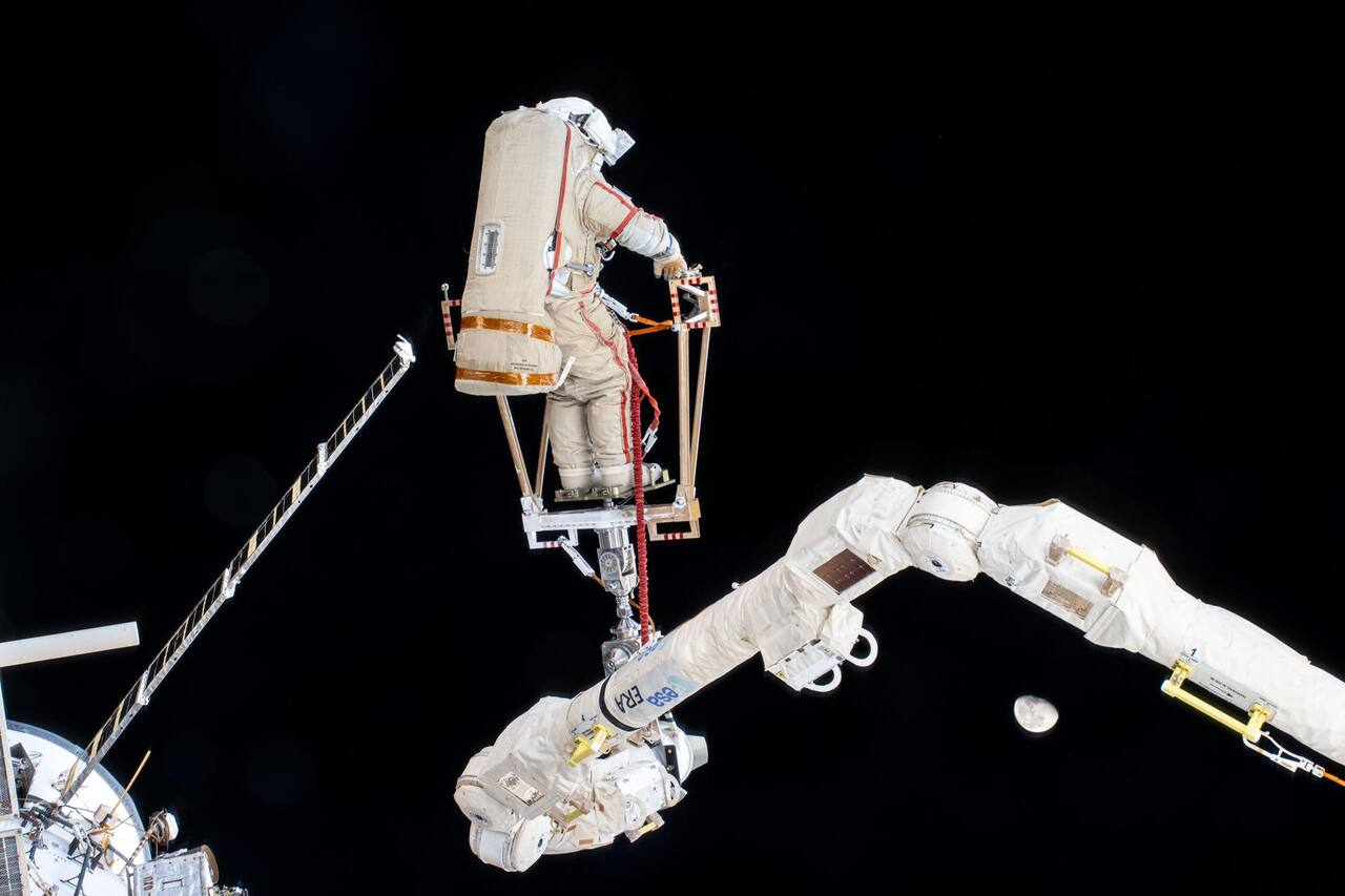 NASA. Public domain (NASA / US government work).
The problem
Section titled “The problem”The Russian segment of the International Space Station needed a manipulator of its own. Canadarm2 and the Japanese Experiment Module arm cannot reach it, and base point and payload interfaces differ between segments [3]. The arm has to move payloads of up to 8000 kg, relocate itself along the segment, and do so at a mass low enough to launch, which makes it far more flexible than an industrial robot: the first bending mode holds over 90 percent of the total inertia and dominates the control problem [1].
The environment adds three constraints. Vacuum removes the liquid and air film that terrestrial brakes and bearings rely on, so friction pairs and lubricants must be qualified in vacuum [2], [5]. Orbital thermal cycling, about 34,000 eclipse transitions per 5.8 years in low Earth orbit as recorded on LDEF, produced microcracking in composites and delamination of coatings [6]. Meteoroids strike external hardware at an average 19 km/s [7]. A fourth constraint applies on the ground: the arm cannot support itself in one gravity, so three-dimensional operation cannot be tested end to end before launch [1].
What has flown
Section titled “What has flown”Shuttle Remote Manipulator System. The Shuttle arm flew 91 missions over 30 years, and its operability record includes uncommanded motion: during LDEF unberthing on STS-41C a pure Z command produced 2.5 inches of X motion over 11.5 inches of commanded Z, about 22 percent cross coupling [14]. A vacuum brake material problem is also recorded, in which an asbestos derivative lost torque through moisture loss [14].
Canadarm2 and Dextre. Canadarm2 has a dry mass of 1497 kg [8], and a survey lists it at 17 m with Dextre at 3.35 m and 7 DOF [34]. Dextre exchanges orbital replacement units in a three-step sequence, and the case for it is crew time saved on external maintenance; the 13.4 EVAs per year avoided come from a 2004 estimate and the paper predates commissioning [15]. Eleven years of Robotic Refueling Mission operations with Dextre-compatible tools cut lock wires, removed caps, mated connectors and transferred 1.7 liters of ethanol, but the lessons are qualitative, with no success rates or contact force measurements [36].
JEMRMS. The Japanese arm’s 1994 development paper tabulates structural eigenvalues: 0.32 and 0.34 Hz unloaded on orbit, 0.19 Hz with a 500 kg payload and 0.046 Hz with a 7000 kg payload, against 14.2 Hz restrained for launch [16]. These are design predictions made before the engineering model existed, to be updated by modal survey [16].
ERA. The arm launched on the Nauka module on 21 July 2021, originally planned for 2001 on the Space Shuttle [3], [13]. Its first planned tasks were airlock setup and radiator installation [13]. One EVA replaceable unit had been launched on STS-132 in 2010 and stored on MRM-1 [1]. No held source reports flight values for its accuracy, brake torque or backlash; the tables below give specification and ground qualification values [1], [2].
Chinese Space Station. The core module arm is credited by the operator with 738 kg, 10.2 m, 25 t drag capacity and 0.6 m/s tip speed, without a stated measurement basis [18]. On 6 January 2022 it unlocked the Tianzhou-2 cargo craft, moved it and re-docked it in 47 minutes; the report gives no loads or alignment data [17]. The experiment module arm carries a six-axis force and torque sensor with 32 strain gauges, ranged at plus or minus 500 N and plus or minus 100 N m, whose vibration and thermal vacuum tests are reported as passed without levels [37].
Robot assistants inside the station. Robonaut 2 arrived in February 2011 and ran fixed-base task board experiments for more than two years, with climbing legs and a battery backpack in preparation [20], [21]. The status report is narrative, with no task success rates or cycle counts [21]. Astrobee replaced SPHERES as an operations tool, which had been confined to a two meter cube by its ultrasonic beacons; the pre-launch description contains no measurements [22]. Int-Ball2 made its first on-orbit demonstration on 17 October 2023, and the on-orbit reference marker system itself carries up to 28 mm position error [38]. A joint review compares Astrobee, CIMON and the Int-Ball vehicles side by side [39].
What is being tried now
Section titled “What is being tried now”Joint and brake design for long life. ERA’s joint is the reference design: a four stage 450:1 planetary train with tandem stage pairs on floating ring wheels [1], and a motor unit with look-up-table current shaping that cut torque ripple from about 15 percent to under 0.3 percent peak to peak [2]. It is qualified for a flight arm, not flight-proven. Newer lubricant work compares silahydrocarbons with the incumbent Bray oil on a spiral orbit tribometer and a vacuum four-ball tribometer; that is ground test only [5].
Closed-form and fast inverse kinematics for SSRMS-type arms. A closed-form solution for the offset roll-yaw-pitch geometry of Canadarm2 and the Chinese arms yields sixteen solution sets; it is simulation only, and its two-orders-of-magnitude speed claim is against a general numerical toolbox [32]. A cyclic coordinate descent hybrid reports a 99.32 percent success rate and 4.86 ms solve time on a laboratory arm model, not comparable to the other methods [31]. A decoupling solution for the Chinese Wentian module arm was tested on more than 10,000 simulated poses without hardware [33]. None has flown.
Servicing and debris removal. A tutorial review ties space manipulators to active debris removal, with figures taken from secondary sources [28]. NASA’s ISAM state of play series sorts manipulators by long and short reach around an 8 m discriminator and lists the Chinese core arm at 7 DOF and 10 m [19]. The 2022 edition shares whole paragraphs with its successor and is not an independent source [27]. A review of orbital servicing technology treats vision and force control as the baseline sensing architecture [9], and the Springer handbook chapter places ERA among the orbital manipulator systems that followed SRMS, ETS-VII and JEMRMS [12].
Telerobotics from orbit. KONTUR-2 flew a 2-DOF force feedback joystick on the Russian segment and measured 20 to 30 ms round trip delay to ground robots over the S-band link, against 65 ms and 5 to 15 percent loss on the training link [24]. The joystick delivers 15 N maximum handle force, and a 1.57 Nm/rad maximum stable stiffness is stated without derivation [25]. ETS-VII, flown in 1999, demonstrated manipulator control experiments and on-orbit inertia identification, each from a single trial [26]; the DLR overview of the same period covers ROTEX and the ground-controlled GETEX experiments [10]. Astrobee’s perching arm has a gripper whose handrail detachment force averaged 6.43 N over five bench trials on one prototype [23]. A proposed standard for lunar arm and tool interfaces defines four notional classes by load, power, data rate and accuracy, with no hardware built to them [40].
Ground facilities. Free-floating servicing dynamics are reproduced on hardware-in-the-loop rigs. DLR’s OOS-SIM uses two KUKA KR120 robots at a 4 ms real-time rate with a common workspace of about 23.28 m3 [30]. York University has built a 6 DOF rig with two manipulators and active gravity compensation, documented only by a one-page abstract [29]. A 2024 survey inventories the ground facilities and the arm specifications, all secondary [35].
The numbers
Section titled “The numbers”| ERA parameter | Value | Source |
|---|---|---|
| Total length | 11.3 m | [4] |
| Reach | 9.7 m | [4] |
| Mass | 630 kg | [4] |
| Rated moveable mass | 8000 kg | [4] |
| Maximum payload dimensions | 3 by 3 by 8.1 m | [1] |
| Maximum tip speed | 0.10 m/s | [4] |
| Braking distance at maximum joint speed | 0.15 m | [1] |
| Positioning accuracy, open loop | +/-40 mm | [1] |
| Positioning accuracy, closed loop | +/-5 mm | [4] |
| Peak power / standby / hibernation heater | 800 W / 420 W / 250 W | [1] |
| Cameras | 4 | [3] |
| Joint motor unit and brake | Value | Source |
|---|---|---|
| Motor stall torque | over 1.45 N m | [2] |
| Motor no-load speed at 30 V | 345 rpm | [2] |
| Motor mass, size | 0.750 kg, 120 mm by 29 mm | [2] |
| Brake torque variation | within +/-22 percent of average | [2] |
| Emergency stop time | under 3.5 s | [2] |
| Qualified duty | 4380 h, over 10,700 operations | [2] |
| Running-in before the brake holds | at least 12,000 revolutions in vacuum | [2] |
| Torque peak with insufficient third-body particles | 1.78 N m against a 1.1 N m limit | [2] |
| Gearbox | four stage planetary, 450:1 (454:1 in the joint hardware paper) | [1], [2] |
| Brake disc separation | 0.25 to 0.30 mm | [1] |
| Station arm | Figure | Source |
|---|---|---|
| Canadarm2 dry mass | 1497 kg | [8] |
| JEMRMS first eigenvalue, 7000 kg payload (design) | 0.046 Hz | [16] |
| Shuttle arm cross coupling, STS-41C | about 22 percent | [14] |
| Chinese core arm, operator figures | 738 kg, 10.2 m, 0.6 m/s | [18] |
| Tianzhou-2 transposition | 47 minutes | [17] |
| Survey values: ERA 11.3 m, 7 DOF; Canadarm2 17 m | listed specifications | [34] |
What is not established
Section titled “What is not established”No held source reports ERA flight performance: accuracy, speed and braking are specification values with no qualification test results or error budget [1]. Brake and motor qualification is unit level and predates launch; the recovery time after ambient exposure and the torque peak correction are stated without data, and the coating’s air and vacuum torque cannot be correlated one to one [2]. System-level operating and survival temperatures are not in the held sources. Three-dimensional operation was qualified by simulation, because only planar motion could be tested on the ground [1]. The Chinese arm figures are agency statements [17], [18], and the JEMRMS eigenvalues are pre-build predictions [16]. The inverse kinematics methods above are simulation results with no flight or hardware comparison [31], [32], [33]. Astrobee and Robonaut 2 results are narrative or bench-scale, without task statistics [21], [23].
References
- Cruijssen, H. J., Ellenbroek, M., Henderson, M., Petersen, H., Verzijden, P. and Visser, M. (2014). The European Robotic Arm: A High-Performance Mechanism Finally on its way to Space
. Aerospace Mechanisms Symposium, NASA Goddard Space Flight Center, 20150004070. Source
BibTeX
@inproceedings{cruijssen2014european, title = {The European Robotic Arm: A High-Performance Mechanism Finally on its way to Space}, author = {Cruijssen, H. J. and Ellenbroek, M. and Henderson, M. and Petersen, H. and Verzijden, P. and Visser, M.}, booktitle = {Aerospace Mechanisms Symposium, NASA Goddard Space Flight Center}, number = {20150004070}, institution = {NASA}, year = {2014}, url = {https://ntrs.nasa.gov/citations/20150004070}, abstract = {This paper describes the design and qualification of the European Robotic Arm (ERA), which is planned to be launched by the end of 2015. After years of changes, a shift of launcher and new loads, launch preparation is underway. The European Robotic Arm ERA has been designed and manufactured by Dutch Space and its subcontractors such as Astrium, SABCA and Stork with key roles for the mechanical aspects. The arm was originally designed to be launched by the STS (mounted on a Russian module for the ISS) in 2001. However, due to delays and the STS disaster, a shift was made to the Russian Proton rocket. ERA will be launched on the Multipurpose Laboratory Module (MLM). This module, which is now planned for launch to the ISS in 2015, will carry the ERA. The symmetrical design of the arm with a complete 3 degree-of-freedom wrist and general-purpose end effector on both sides, allows ERA to relocate on the station by grappling a new base point and releasing the old one, and move to different working locations. } } - Baker, F. C., Favre, E., Mozzon, J.-M., Crausaz, A. and Juriens, P. (1999). European Robotic Arm (ERA) Manipulator Joint System Motor Unit and Tribological Brake
. European Space Mechanisms and Tribology Symposium. Source
BibTeX
@inproceedings{baker1999european, title = {European Robotic Arm (ERA) Manipulator Joint System Motor Unit and Tribological Brake}, author = {Baker, F. C. and Favre, E. and Mozzon, J.-M. and Crausaz, A. and Juriens, P.}, booktitle = {European Space Mechanisms and Tribology Symposium}, address = {Toulouse}, year = {1999}, url = {https://www.esmats.eu/esmatspapers/pastpapers/pdfs/1999/baker.pdf} } - European Space Agency. (2021). European Robotic Arm: The International Space Station's Latest Upgrade
. ESA Human and Robotic Exploration. Source
BibTeX
@techreport{esa2021european, title = {European Robotic Arm: The International Space Station's Latest Upgrade}, author = {{European Space Agency}}, institution = {ESA Human and Robotic Exploration}, year = {2021}, url = {https://esamultimedia.esa.int/docs/science/ERA_brochure_EN.pdf} } - European Space Agency. (2021). European Robotic Arm (ERA)
. ESA ISS Factsheet 7. Source
BibTeX
@techreport{esa2021europeanb, title = {European Robotic Arm (ERA)}, author = {{European Space Agency}}, institution = {ESA ISS Factsheet 7}, year = {2021}, url = {https://wsn.spaceflight.esa.int/docs/Factsheets/7%20ERA%20LR.pdf} } - Jones, W. R. J., Jansen, M. J., Gschwender, L. J., Snyder, C. E. J., Sharma, S. K., Predmore, R. E. and Dube, M. J. (2001). The Tribological Properties of Several Silahydrocarbons for Use in Space Mechanisms
. Journal of Synthetic Lubrication, NASA/TM-2001-211196. Source
BibTeX
@article{jones2001tribological, title = {The Tribological Properties of Several Silahydrocarbons for Use in Space Mechanisms}, author = {Jones, W. R., Jr. and Jansen, M. J. and Gschwender, L. J. and Snyder, C. E., Jr. and Sharma, Shiv K. and Predmore, R. E. and Dube, Michael J.}, journal = {Journal of Synthetic Lubrication}, volume = {20}, number = {NASA/TM-2001-211196}, pages = {303-315}, institution = {NASA}, address = {Liege}, year = {2001}, doi = {10.1002/jsl.3000200404}, abstract = {Abstract Silahydrocarbons are members of a relatively new class of liquid lubricants with great potential for use in space mechanisms. They are unimolecular species consisting of silicon, carbon, and hydrogen. They possess unique wear, viscosity, and volatility properties while retaining the ability to solubilise conventional additives. The tribological properties of several members of this class, including tri‐, tetra‐, and penta‐compounds, are presented. These properties include viscosity‐temperature, viscosity—pressure, vapour pressure, lubricant life, traction, and reciprocating and four‐ball wear rates. Lubricant lifetimes were determined using a vacuum ball bearing simulator, the spiral orbit tribometer. Wear was measured using a Cameron Plint reciprocating tribometer and wear rates with a vacuum four‐ball tribometer. Conventional viscometry was used for viscosity—temperature measurements and a Knudsen cell for vapour pressure. Thermogravimetric analysis was also used for volatility measurements. Pressure—viscosity coefficients (α—values) were estimated from elastohydrodynamic lubrication film thickness measurements. These properties are compared to those of existing state‐of‐the‐art space lubricants.} } - Stein, B. A. (1992). An interim overview of LDEF materials findings
. NASA, NASA-TM-107664. Source
BibTeX
@techreport{stein1992interim, title = {An interim overview of LDEF materials findings}, author = {Stein, Brad A.}, number = {NASA-TM-107664}, institution = {NASA}, year = {1992}, url = {https://ntrs.nasa.gov/citations/19930009140}, abstract = {The flight and retrieval of the National Aeronautics and Space Administration's Long Duration Exposure Facility (LDEF) provided an opportunity for the study of the low-Earth orbit (LEO) environment and long-duration space environmental effects (SEE) on materials that is unparalleled in the history of the U.S. Space Program. The remarkable flight attitude stability of LDEF enables specific analyses of various individual and combined effects of LEO environmental parameters on identical materials on the same space vehicle. This paper provides an overview of the interim LDEF materials findings of the Principal Investigators and the Materials Special Investigation Group. In general, the LDEF data is remarkably consistent; LDEF will provide a 'benchmark' for materials design data bases for satellites in low-Earth orbit. Some materials were identified to be encouragingly resistant to LEO SEE for 5.8 years; other 'space qualified' materials displayed significant environmental degradation. Molecular contamination was widespread; LDEF offers an unprecedented opportunity to provide a unified perspective of unmanned LEO spacecraft contamination mechanisms. New material development requirements for long-term LEO missions have been identified and current ground simulation testing methods/data for new, durable materials concepts can be validated with LDEF results. LDEF findings are already being integrated into the design of Space Station Freedom.} } - Moorhead, A. V. (2020). NASA Meteoroid Engineering Model (MEM) Version 3
. NASA, NASA/TM-2020-220555. Source
BibTeX
@techreport{moorhead2020nasa, title = {NASA Meteoroid Engineering Model (MEM) Version 3}, author = {Moorhead, A. V.}, number = {NASA/TM-2020-220555}, institution = {NASA}, year = {2020}, url = {https://ntrs.nasa.gov/citations/20200000563}, abstract = {The Meteoroid Engineering Model (MEM) version 3 is NASA’s most current and accurate model of the meteoroid environment. MEM 3 supersedes all previous versions of MEM, including MEM Release 2.0 (MEMR2), MEM Release 1.0c (MEMR1c), and previously internally controlled and released versions of MEMCxP v2.0 and LunarMEM v2.0. Earlier versions of MEM superseded older models of the meteoroid environment such as the Grün model and its derivative, Technical Memo 4527 (hereafter abbreviated as TM 4527) [1]. Prior to the establishment of the NASA Meteoroid Environment Office (MEO), NASA’s meteoroid environment models relied on a simple empirical expression derived from [2], as described in [3] and later in [1]. This expression describes the meteoroid flux incident on a flat plate near 1 au. TM 4527 assumes an isotropic environment, making the orientation of the plate irrelevant [4]. The flux was combined with scale factors to account for the reduction in flux occurring when the Earth shields the spacecraft from a portion of the meteoroid environment and the enhancement in flux due to the focusing effect of Earth’s gravitational field. TM 4527 also introduced a crude, piecewise meteoroid speed distribution with an average velocity of 19 km/s for an orbiting spacecraft based on [5]. Finally, TM 4527 assumed a three-step density distribution in which dust particles smaller than 10−6 g have a density of 2 g/cu cm, micrometeoroids between 10−6 g and 0.01 g have a density of 1 g/cu cm, and meteoroids larger than 0.01 g have a density of 0.5 g/cm3. Thus, the meteoroid model presented in TM 4527 was assembled from multiple independent sources. The model of TM 4527 was also used for years in Space Station risk assessments, and is described in Space Station Specification (SSP) 30425.} } - (2026). CSA: Canadarm2. asc-csa.gc.ca/eng/iss/canadarm2
BibTeX
@misc{csacanadarm2, title = {CSA: Canadarm2}, organization = {asc-csa.gc.ca}, year = {2026}, url = {https://www.asc-csa.gc.ca/eng/iss/canadarm2/} } - Flores-Abad, A., Ma, O., Pham, K. and Ulrich, S. (2014). A review of space robotics technologies for on-orbit servicing
. Progress in Aerospace Sciences. Source
BibTeX
@article{floresabad2014review, title = {A review of space robotics technologies for on-orbit servicing}, author = {Flores-Abad, Angel and Ma, Ou and Pham, Khanh and Ulrich, Steve}, journal = {Progress in Aerospace Sciences}, volume = {68}, pages = {1-26}, publisher = {Elsevier BV}, year = {2014}, doi = {10.1016/j.paerosci.2014.03.002} } - Hirzinger, G., Brunner, B., Lampariello, R., Landzettel, K., Schott, J. and Steinmetz, B.-M. (2000). Advances in orbital robotics
. IEEE International Conference on Robotics and Automation. Source
BibTeX
@inproceedings{hirzinger2000advances, title = {Advances in orbital robotics}, author = {Hirzinger, G. and Brunner, B. and Lampariello, R. and Landzettel, K. and Schott, J. and Steinmetz, B.-M.}, booktitle = {IEEE International Conference on Robotics and Automation}, volume = {1}, pages = {898-907}, year = {2000}, doi = {10.1109/robot.2000.844163}, abstract = {Outlines the situation in orbital space robotics with special reference to what DLR (German Aerospace Center) has contributed to the field. After our ROTEX experiment, the first remotely controlled space robot inside the space shuttle, the Japanese ETS VII has now been the first remotely controlled free-flying space robot. We had the opportunity to control this arm from the ground, too, including the use of the robot arm as a satellite attitude controller. It is outlined how it is now time to take the next steps towards operational ground-controlled space robot systems, presumably first on the International Space Station, but later on as free flying robonauts assisting or even replacing extra vehicular activities.} } - Yoshida, K., Wilcox, B., Hirzinger, G. and Lampariello, R. (2016). Space Robotics
. Springer Handbook of Robotics. Source
BibTeX
@incollection{yoshida2016space, title = {Space Robotics}, author = {Yoshida, Kazuya and Wilcox, Brian and Hirzinger, Gerd and Lampariello, Roberto}, booktitle = {Springer Handbook of Robotics}, series = {Springer Handbooks}, pages = {1423-1462}, publisher = {Springer International Publishing}, year = {2016}, doi = {10.1007/978-3-319-32552-1_55} } - (2026). ESA: European Robotic Arm. esa.int/Science_Exploration/Human_and_Robotic_Exploration/Internation...
BibTeX
@misc{esaeuropean,
  title = {ESA: European Robotic Arm},
  organization = {esa.int},
  year = {2026},
  url = {https://www.esa.int/Science_Exploration/Human_and_Robotic_Exploration/International_Space_Station/European_Robotic_Arm}
}
Further reading
- Li, D. and Wang, Y. (2015). Overview of the Chinese Space Station Manipulator . AIAA SPACE Conference. Source