CNSA Extraterrestrial Body Landing Comprehensive Test Field
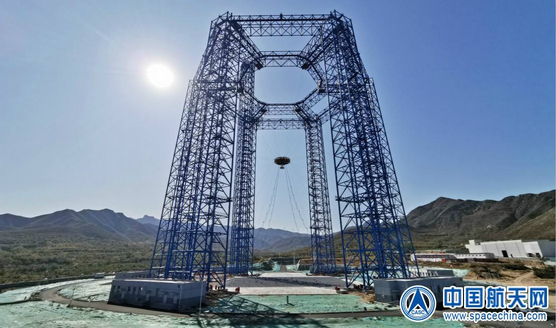
China Aerospace Science and Technology Corporation.
The Extraterrestrial Body Landing Comprehensive Test Field at Huailai County, Hebei (Chinese name 地外天体着陆综合试验场) is described by CNSA as the largest of its kind in Asia [2]. The English form used here is the one carried in the reporting of the 2019 test and has no operator-published equivalent.
The problem
Section titled “The problem”A lander or ascent vehicle has to be tested in its last phase of flight: hover, hazard avoidance, slow descent, touchdown, and on the ascent side ignition and lift-off. On Earth the vehicle weighs three to six times what it will weigh on the Moon or Mars, and the engines and guidance loops are sized for the lower weight. A test field therefore has to remove part of the weight without adding inertia, friction or lateral force to a vehicle that moves in three dimensions.
Huailai does this with a three-dimensional follow-up system. The vehicle hangs from a cable that pulls upward with a constant force so the net downward force matches the target body, while the support tracks the vehicle in three dimensions so the cable stays vertical [1]. The tradeoff is general to suspension offload: the support hardware has mass, friction and stiffness of its own, and those do not shrink because the cable carries less than the full weight [1][5]. The Apollo answer, the Lunar Landing Research Facility at Langley (1965), hung a lander simulator from a gantry on cables carrying five sixths of its weight so astronauts could practice descent [5].
What has flown
Section titled “What has flown”The field has not flown; it qualified vehicles that did. The campaigns below are the public record, and the operator sources are press items that state dates and scope but no measured result [2][3][4].
Chang’e-3. The spacecraft hovers at 100 m above the surface to select a site, translates to it, descends slowly, and below 4 m shuts down the main engine and free-falls [1]. The follow-up system reproduced the hover, avoidance and slow-descent segments with rope tension balancing part of the vehicle weight. Chang’e-3 landed at 19.51 W, 44.12 N in northern Mare Imbrium on 14 December 2013 and deployed the Yutu rover on 15 December [14].
Chang’e-5. The campaign added take-off testing, which drove the addition of upper and lower stay cable drives [1]. Test masses were 1.5 t for landing and 0.8 t for take-off on a 20 t platform. The flight drill recovered about 1 m of core against a goal of about 2 m, with no analysis of why [17]. See chang-e-5-sampler.
Tianwen-1. On 14 November 2019 the lander ran hovering, obstacle avoidance and slow descent under a simulated gravity of about one third of Earth’s, as a check of design correctness [3]. It was the Mars program’s first public appearance, observed by envoys from 19 countries and by representatives of the EU, the African Union and APSCO [2][3]. Zhurong’s designers state a landing-site rock coverage about twice that of the Moon as a terrain driver and describe an active rocker-arm suspension with three self-extraction modes, as design statements with no test result [15]. See zhurong.
Lanyue, 6 August 2025. The comprehensive landing and take-off verification of the crewed lunar lander was completed at Huailai, the first such test of a crewed spacecraft in China [4]. It covered the landing and take-off system scheme, the control scheme, the touchdown engine cutoff scheme and the guidance, navigation and control to propulsion interfaces. Lanyue has a lunar module and a propulsion module and carries two astronauts [4]. It has not flown.
None of the flight outcomes is traced to a Huailai measurement in the sources held, so the field’s predictive accuracy against flight is not established. Yutu-2 later operated under a relay loop in which the first telemetry frame arrives 80 to 100 s after a command and execution is confirmed after 3 to 4 minutes, at a nominal 3.3 m/min [16]. A descent test does not reproduce that constraint.
What is being tried now
Section titled “What is being tried now”Cable-parallel drive at Huailai (ground tested, used for flight qualification). The Mars lander system replaced the gantry crane form with cable-parallel drive: 18 drive units and 36 wire ropes connect to the platform, driven by 24 AC servo motors [2][3]. The main hoist has six ground units with parallelogram stays from 133 m, the upper stay system six units at 84 m, and the lower stay six ground units at about 7 m. On the platform, three motors form the fast horizontal follow-up and three the tension fine-adjustment device [1]. The 36 rope tensions are planned by minimum-variance optimization, and rope length error is calibrated on a grid with bilinear interpolation. Measured cable inclination was at most 0.17 degrees, about 12 mm at a 4 m cable length [1].
Other suspension rigs (ground tested). NASA’s ARGOS holds a constant upward force on a suspended subject through a gantry robot over more than 340 cubic meters, at up to 3.3 m/s, detecting faults in under 20 ms [8]. Its three active and three passive degrees of freedom address the limits of POGO, parabolic flight and neutral buoyancy [7]. Across 14 subjects and 68 pivot configurations, a gimbal pivot at the payload center of gravity left the subject unstable; the usable zone was 2.5 to 6.4 cm above and 1.3 to 2.5 cm aft of it [6]. Halving the suspended gimbal mass from 105 lb to 53 lb improved subject ratings [7]. DLR’s LAMA, built for the Philae lander, showed that the suspension perturbs the touchdown it measures: a tilt limiter specified for plus or minus 3 degrees permitted at least 9 degrees, and touchdown detection triggered at 0.5 m/s on soft ground but 0.2 m/s on hard ground [9]. A retest found the suspension stiffness, 4080 N/m, more than sixteen times the pendulum rig’s 242 N/m, a difference corrected against 1996 to 2002 baseline data [10]. At small scale, IRGO, a Michigan Tech two-axis trolley tracking an infrared beacon over 3800 kg of simulant with a passive counterweight, has a stationary error of 0.3 mm and an untested control loop; it is laboratory only [13].
Reduced vehicle mass with Earth-gravity soil (ground practice, known bias). Coupled granular-dynamics simulation shows this practice gives optimistic trafficability: a 73 kg test rover climbing 30 degrees at about 42 percent slip corresponds to a 440 kg lunar-mass rover at about 85 percent slip, above the roughly 80 percent dig-in threshold, and at 10 degrees slip goes from 18 to about 75 percent [11][12]. Parabolic flight with soil and wheel both at lunar gravity measured drawbar pull to weight falling 20 percent or more and sinkage rising up to 40 percent against reduced-weight testing; granular scaling laws came within 8.5 percent on drawbar pull and erred conservatively [19]. Huailai holds the vehicle at flight mass and adjusts only net force, so it does not import this error, but its terrain field is undocumented.
Magnetic levitation of soil (laboratory only). A magnetic-gravity rig at 1/6 g, 1 g and 2 g measured cone penetration resistance 29.1 percent lower at 1/6 g than at 1 g at 40 percent relative density but only 8.8 percent lower at 76 percent, in a 95 mm by 160 mm chamber with a magnetite simulant [18]. It measures soil strength, not vehicle landing.
Consolidated practice (review, not data). NASA’s 2025 mobility test guide states that no known facility reproduces the inertial and dynamic effects of a fast vehicle specified to 15 km/h, and that cone index gradient as a lunar strength match is of uncertain validity under lunar gravity [20].
The numbers
Section titled “The numbers”Laboratory data
Section titled “Laboratory data”| Parameter | Value |
|---|---|
| Operator | Not established in open sources [2][3] |
| Location | Huailai County, Hebei Province, China [2][3] |
| Commissioned | Chang’e-3 era, upgraded for Chang’e-5, rebuilt for the Mars lander [1] |
| Type | Outdoor gravity-offload landing and take-off test field |
| Floor area | Not published. Ground drive units sit on a 60 m radius circle [1] |
| Simulant or terrain | Not published |
| Ground truth | Suspension-point encoder and gyroscope for rope inclination; rope tension from motor torque [1] |
| Access | National program facility. No external user route published [2] |
| Cited by | zhurong, chang-e-5-sampler |
Three-dimensional follow-up system
Section titled “Three-dimensional follow-up system”| Parameter | Value |
|---|---|
| Working volume | 20 x 20 x 80 m [1] |
| Tension range | 0 to 20 kN, continuously adjustable; dynamic capacity 3x static [1] |
| Offload accuracy | Constant tension, 3 parts per thousand or better; tension error below 20 N [1] |
| Moving mass of platform | Over 20 t |
| Maximum cable inclination | 0.17 deg, about 12 mm at 4 m [1] |
| Carriage tracking error | 7.1 mm, upper carriage rise time 0.72 s |
| Coupled sway, limit case | Under 5 cm measured; 8 to 9 cm simulated at 60 m height [1] |
| Horizontal stiffness | Above 1.8 x 10^6 N/m, about 1.4 x 10^6 N/m above 80 m [1] |
| Vacuum, temperature | Outdoors at ambient pressure, not controlled [2] |
Earlier builds
Section titled “Earlier builds”| Parameter | Value |
|---|---|
| Chang’e-3 | Three levels: 100 m coarse travel on rails, 16 x 16 m servo gear and rack, and the fast follow-up platform on six wire ropes [1] |
| Chang’e-5 | 18 ropes: six upper stay from 80 m height and 70 m radius, six lower stay from 5 m and 60 m, six main hoist; 60 degree spacing [1] |
| Chang’e-5 drives | Main hoist two 845 kW motors at 1250 rpm; upper stay six 540 kW; lower stay six 359 kW |
| Wire rope | 22 mm diameter, 217 mm2 effective section |
Average set tensions by platform height [1]:
| Rope set | 80 m | 50 m | 10 m |
|---|---|---|---|
| Upper stay | 2.17 t | 2.18 t | 1.36 t |
| Lower stay | 1.80 t | 2.10 t | 2.10 t |
| Main hoist | 10.00 t | 9.00 t | 6.60 t |
Comparison rigs
Section titled “Comparison rigs”| Rig | Figure |
|---|---|
| ARGOS | More than 340 m3, 3.3 m/s, fault detection under 20 ms [8] |
| Langley LLRF | 240 ft high, 400 ft long, 265 ft wide, drop height about 200 ft, bridge crane 65,000 lb [5] |
| LAMA suspension stiffness | 4080 N/m against 242 N/m for the pendulum [10] |
| IRGO | 0.3 mm stationary error, 3800 kg simulant [13] |
What is not established
Section titled “What is not established”The operator of the field is not named in open sources, and no source gives the terrain field’s composition, depth, grain size or whether it is a simulant [1]. The official items give no measured quantity: no offload accuracy achieved, hover altitude, descent rate or pass criterion [2][3][4]. The published system paper gives no residual vertical force and no control bandwidth, and its 8 to 9 cm sway figures are simulation. The designers chose suspension over other methods because it follows actively, not because it is exact [1].
Gravity is compensated, not changed. Internal masses, propellant slosh and any gravity-dependent behavior inside the vehicle still see 1 g. Suspension compensation must overcome the friction and inertia of the hardware, horizontal following is vulnerable to rope vibration, and the two couple and can destabilize the system [1]. Stiffness is bought with pretension, which costs motor power: the target is the smallest pretension that meets the requirement [1].
The envelope is the last 100 m: hover, avoidance, slow descent and touchdown, and for take-off the constant-tension hold before unlock and constant-force following after ignition [1]. The rest of the descent and the Mars entry phases are outside the field.
Whether 1 g and reduced-gravity soil tests agree is itself disputed [19][20]. Parabolic flight data and magnetic-gravity data on cone resistance differ in simulant, density and method, and the penetration resistance measured in the latter is not the cone index gradient the former reports [18][19]. Fast-vehicle dynamics have no known facility [20].
References
Section titled “References”References
- Dong, Q., Chen, Q., Huang, K., Xing, W. and Shen, B. (2023). A Three-Dimensional Follow-Up System for a Spacecraft Low-Gravity Simulation Test Platform
. Journal of Tsinghua University, 3. Source
BibTeX
@article{dong2023three, title = {A Three-Dimensional Follow-Up System for a Spacecraft Low-Gravity Simulation Test Platform}, author = {Dong, Qiang and Chen, Qiang and Huang, Ke and Xing, Wei and Shen, Bing}, journal = {Journal of Tsinghua University}, volume = {63}, number = {3}, pages = {449--460}, year = {2023}, doi = {10.16511/j.cnki.qhdxxb.2022.26.056} } - (2019). CNSA Invites Diplomatic Envoys and Media to Observe the Lander Hovering and Obstacle Avoidance Test of China's First Mars Exploration Mission. cnsa.gov.cn/n6758824/n6759009/n6760412/n6760413/c6840424/content.html
BibTeX
@misc{anon2019cnsa, title = {CNSA Invites Diplomatic Envoys and Media to Observe the Lander Hovering and Obstacle Avoidance Test of China's First Mars Exploration Mission}, organization = {China National Space Administration}, year = {2019}, url = {https://www.cnsa.gov.cn/n6758824/n6759009/n6760412/n6760413/c6840424/content.html} } - (2019). Hovering and Obstacle Avoidance Test of the Lander for China's First Mars Exploration Mission Completed. spacechina.com/n25/n2014789/n2014804/c2783609/content.html
BibTeX
@misc{anon2019hovering, title = {Hovering and Obstacle Avoidance Test of the Lander for China's First Mars Exploration Mission Completed}, organization = {China Aerospace Science and Technology Corporation}, year = {2019}, url = {https://www.spacechina.com/n25/n2014789/n2014804/c2783609/content.html} } - (2025). Comprehensive Landing and Take-off Verification Test of the Lanyue Lunar Lander Completed Successfully. cnsa.gov.cn/n6758823/n6758838/c10694156/content.html
BibTeX
@misc{anon2025comprehensive, title = {Comprehensive Landing and Take-off Verification Test of the Lanyue Lunar Lander Completed Successfully}, organization = {China National Space Administration}, year = {2025}, url = {https://www.cnsa.gov.cn/n6758823/n6758838/c10694156/content.html} } - NASA Langley Research Center. (2022). Landing and Impact Research Facility (LandIR). researchdirectorate.larc.nasa.gov/landing-and-impact-research-facilit...
BibTeX
@misc{larc2022landir, title = {Landing and Impact Research Facility (LandIR)}, author = {{NASA Langley Research Center}}, organization = {researchdirectorate.larc.nasa.gov}, year = {2022}, url = {https://researchdirectorate.larc.nasa.gov/landing-and-impact-research-facility-landir/} } - Jarvis, S. L., Vu, L. Q., Gupta, G., Benson, E., Kim, K. H., Rhodes, R. and Rajulu, S. L. (2023). Development of ARGOS (Active Response Gravity Offload System) Offloading Assessments and Methodology for Lunar EVA Simulations
. International Conference on Environmental Systems, 20230002430. Source
BibTeX
@inproceedings{jarvis2023development, title = {Development of ARGOS (Active Response Gravity Offload System) Offloading Assessments and Methodology for Lunar EVA Simulations}, author = {Jarvis, Sarah L. and Vu, Linh Q. and Gupta, Garima and Benson, Elizabeth and Kim, K. Han and Rhodes, Richard and Rajulu, Sudhakar L.}, booktitle = {International Conference on Environmental Systems}, number = {20230002430}, institution = {NASA}, address = {Calgary}, year = {2023}, url = {https://ntrs.nasa.gov/citations/20230002430}, abstract = {The Active Response Gravity Offload System (ARGOS) at NASA Johnson Space Center (JSC) is an analog environment that can offload pressurized suited subjects for various reduced gravity simulations. The suit is suspended from a robotic overhead crane by a cable connected to the suit via a gimbal with an adjustable pivot point (i.e. offload attachment). There has been increased interest in providing planetary pressurized suited training at ARGOS in preparation for lunar missions. Determination of the appropriate gimbal pivot point location for a given subject is vital for a high-fidelity functional lunar simulation. Interactions between the pivot point location and human-spacesuit center of gravity (CG) can result in righting moments that may lead to artificially stable or unrealistically challenging configurations. Changing the pivot point location is time consuming and repeated adjustment can result in loss of valuable pressurized suited time. This paper aims to share knowledge obtained from the offloading characterization efforts during pressurized suited testing at ARGOS and document the ongoing process to define an appropriate pivot point location through iterative quantitative and qualitative assessments. Human-spacesuit CG locations for the ARGOS lunar simulation were estimated using a 3D body scan and density model combined with spacesuit hardware CAD and specifications. Early pilot testing of the gimbal revealed that setting the pivot point coincident with the modeled CG location was not always possible due to the current gimbal design, and small pivot point shifts had noticeable effects on subject stability. Fourteen subjects performed a series of CG-related tasks in the Exploration Extravehicular Mobility Unit (xEMU) to assess simulation characteristics. Through iterative testing, this task list evolved to streamline the process needed to efficiently identify a suitable pivot point for a given subject. The developed methodology will be critical for pivot point selection during astronaut training in the ARGOS environment.} } - Bekdash, O. S., Valle, P. S., Kim, K. J., Jarvis, S. L., Dunn, J. T., Norcross, J. R. and Abercromby, A. F. J. (2020). Development and Evaluation of the Active Response Gravity Offload System as a Lunar and Martian EVA Simulation Environment
. International Conference on Environmental Systems, 20205003610. Source
BibTeX
@inproceedings{bekdash2020development, title = {Development and Evaluation of the Active Response Gravity Offload System as a Lunar and Martian EVA Simulation Environment}, author = {Bekdash, Omar S. and Valle, Paul S. and Kim, Kyoung Jae and Jarvis, Sarah L. and Dunn, Jocelyn T. and Norcross, Jason R. and Abercromby, Andrew F. J.}, booktitle = {International Conference on Environmental Systems}, number = {20205003610}, institution = {NASA}, year = {2020}, url = {https://ntrs.nasa.gov/citations/20205003610}, abstract = {In preparation for future exploration missions, NASA seeks the ability to simulate partial-gravity operations for use in ground-based research, crew training, and engineering design evaluations. The Active Response Gravity Offload System (ARGOS) at the Johnson Space Center (JSC) is designed to simulate reduced gravity environments, such as lunar, Martian, or microgravity, using a robotic system similar to an overhead bridge crane. ARGOS continuously offloads a portion of a suited human’s weight during all dynamic motions within the test facility, which can include basic functional movements such as walking, running, and jumping, as well as a wide range of planetary surface activities. This system will be used as part of a metabolic-rate task characterization study to determine the workload associated with partial-gravity extravehicular activity (EVA). Pilot testing was conducted using the MKIII prototype planetary space suit and two gimbal designs to determine the ability of the ARGOS test environment to simulate planetary EVA operations. This paper will describe the lessons learned from the feasibility testing, simulation-environment mockup design, and the results from the pilot tests and their influence into the final study design. Being able to effectively simulate partial-gravity environments and characterize the performance of crewmembers will have an impact on multiple domains including suit design, task design, thermal models, and life-support-system capacity verification plans, among others.} } - Valle, P. S. (2017). Reduced Gravity Testing of Robots (and Humans) Using the Active Response Gravity Offload System. ntrs.nasa.gov/citations/20170008856
BibTeX
@misc{valle2017reduced, title = {Reduced Gravity Testing of Robots (and Humans) Using the Active Response Gravity Offload System}, author = {Valle, Paul Steinar}, howpublished = {Presentation at the Institute of Electrical and Electronics Engineers}, year = {2017}, url = {https://ntrs.nasa.gov/citations/20170008856}, abstract = {No abstract available} } - Schröder, S., Biele, J., Block, J., Roll, R., Ulamec, S. and Witte, L. (2013). Philae Landing Test at the Landing and Mobility Test Facility (LAMA)
. International Astronautical Congress, IAC-13, A3, 4, 3. Source
BibTeX
@inproceedings{schroder2013philae, title = {Philae Landing Test at the Landing and Mobility Test Facility (LAMA)}, author = {Schröder, Silvio and Biele, Jens and Block, Joachim and Roll, Reinhard and Ulamec, Stephan and Witte, Lars}, booktitle = {International Astronautical Congress, IAC-13, A3, 4, 3}, address = {Beijing}, year = {2013}, url = {https://elib.dlr.de/103154/} } - Witte, L., Schroeder, S., Kempe, H., van Zoest, T., Roll, R., Ulamec, S., Biele, J. and Block, J. (2014). Experimental Investigations of the Comet Lander Philae Touchdown Dynamics
. Journal of Spacecraft and Rockets. Source
BibTeX
@article{witte2014experimental, title = {Experimental Investigations of the Comet Lander Philae Touchdown Dynamics}, author = {Witte, Lars and Schroeder, Silvio and Kempe, Henning and van Zoest, Tim and Roll, Reinhard and Ulamec, Stephan and Biele, Jens and Block, Joachim}, journal = {Journal of Spacecraft and Rockets}, volume = {51}, pages = {1885-1894}, year = {2014}, doi = {10.2514/1.a32906}, abstract = {The comet lander Philae (as part of Europe’s Rosetta mission) is en route to its target, 67/P Churyumov-Gerasimenko. With landing operations coming up at the end of 2014, a partial retesting of the Philae lander’s touchdown system was carried out in spring of 2013. Intensive testing was performed as part of Philae’s design and verification program approximately 10 years ago. However, the new test series specifically addresses touchdown conditions that have been out of capability of the pendulum test facility used at those times. Thus, the follow-up tests focus on touchdown conditions such as asymmetric loads, effects from terrain undulation, and the effect of granular soil mechanics, which could not be studied sufficiently in the original tests. This paper provides insight into the touchdown system of the Philae lander, the characteristics of the used test facility, its weight offloading operating mode, and the specific application to a small-body landing test. The results of the study are presented and discussed in terms of their importance to the ongoing landing preparations.} } - Hu, W., Li, P., Rogg, A., Schepelmann, A., Creager, C., Chandler, S., Kamrin, K. and Negrut, D. (2024). Using physics-based simulation towards eliminating empiricism in extraterrestrial terramechanics applications
. arXiv preprint. Source
BibTeX
@article{hu2024physics, title = {Using physics-based simulation towards eliminating empiricism in extraterrestrial terramechanics applications}, author = {Hu, Wei and Li, Pei and Rogg, Arno and Schepelmann, Alexander and Creager, Colin and Chandler, Samuel and Kamrin, Ken and Negrut, Dan}, journal = {arXiv preprint}, year = {2024}, doi = {10.13140/rg.2.2.33352.94728} } - Hu, W., Li, P., Rogg, A., Schepelmann, A., Chandler, S., Kamrin, K. and Negrut, D. (2025). A Study Demonstrating that Using Gravitational Offset to Prepare Extraterrestrial Mobility Missions is Misleading
. NASA, 20250001809. Source
BibTeX
@techreport{hu2025study, title = {A Study Demonstrating that Using Gravitational Offset to Prepare Extraterrestrial Mobility Missions is Misleading}, author = {Hu, Wei and Li, Pei and Rogg, Arno and Schepelmann, Alexander and Chandler, Samuel and Kamrin, Ken and Negrut, Dan}, number = {20250001809}, institution = {NASA}, year = {2025}, doi = {10.1002/rob.22597}, abstract = {Recently, there has been a surge of international interest in extraterrestrial exploration targeting the Moon, Mars, the moons of Mars, and various asteroids. This contribution discusses how current state-of-the-art Earth-based testing for designing rovers and landers for these missions currently leads to overly optimistic conclusions about the behavior of these devices upon deployment on the targeted celestial bodies. The key misconception is that gravitational offset is necessary during the terramechanics testing of rover and lander prototypes on Earth. The body of evidence supporting our argument is tied to a small number of studies conducted during parabolic flights and insights derived from newly revised scaling laws. We argue that what has prevented the community from fully diagnosing the problem at hand is the absence of effective physics-based models capable of simulating terramechanics under low gravity conditions. We developed such a physics-based simulator and utilized it to gauge the mobility of early prototypes of the Volatiles Investigating Polar Exploration Rover (VIPER). This contribution discusses the results generated by this simulator, how they correlate with physical test results from the NASA-Glenn SLOPE lab, and the fallacy of the gravitational offset in rover and lander testing. The simulator, which is open-sourced and publicly available, supports trafficability analysis and facilitates principled studies into in-situ resource utilization activities like digging, bulldozing, and berming in low gravity environments.} } - Wavrunek, T. A. (2021). Active Gravity Offloading System with Infrared Tracking for Rover Testing
. Michigan Technological University. Source
BibTeX
@mastersthesis{wavrunek2021active, title = {Active Gravity Offloading System with Infrared Tracking for Rover Testing}, author = {Wavrunek, Travis A.}, publisher = {Michigan Technological University}, school = {Michigan Technological University}, type = {Master of Science report, Mechanical Engineering}, year = {2021}, doi = {10.37099/mtu.dc.etdr/1213}, abstract = {Gravity offloading is a tool used to test how different gravitational forces will impact the mobility of rovers bound for Lunar or Martian expeditions. Previous approaches have been successful in simulating partial gravity environments, and this report details how the Infrared- Gravity offload (IRGO) system, developed for the Planetary Surface Technology Development Laboratory (PSTDL) and lunar simulant sandbox, has a similar aim. Through a series of iterations, IRGO has been developed to actively track an infrared beacon and follow a rover within the test chamber to eliminate inertial and friction forces along two horizonal axes. A portion of a rover’s weight is offloaded using a passive counterweight system to provide a third translational degree of freedom. Future plans to incorporate a lightweight gimbal as well as an active vertical axis are also discussed as solutions to improving the IRGO system.} } - Ip, W.-H., Yan, J., Li, C.-L. and Ouyang, Z.-Y. (2014). Preface: The Chang'e-3 lander and rover mission to the Moon
. Research in Astronomy and Astrophysics, 12. Source
BibTeX
@article{ip2014preface, title = {Preface: The Chang'e-3 lander and rover mission to the Moon}, author = {Ip, Wing-Huen and Yan, Jun and Li, Chun-Lai and Ouyang, Zi-Yuan}, journal = {Research in Astronomy and Astrophysics}, volume = {14}, number = {12}, pages = {1511--1513}, year = {2014}, doi = {10.1088/1674-4527/14/12/001}, abstract = {The Chang'e-3 (CE-3) lander and rover mission to the Moon was an intermediate step in China's lunar exploration program, which will be followed by a sample return mission. The lander was equipped with a number of remote-sensing instruments including a pair of cameras (Landing Camera and Terrain Camera) for recording the landing process and surveying terrain, an extreme ultraviolet camera for monitoring activities in the Earth's plasmasphere, and a first-ever Moon-based ultraviolet telescope for astronomical observations. The Yutu rover successfully carried out close-up observations with the Panoramic Camera, mineralogical investigations with the VIS-NIR Imaging Spectrometer, study of elemental abundances with the Active Particle-induced X-ray Spectrometer, and pioneering measurements of the lunar subsurface with Lunar Penetrating Radar. This special issue provides a collection of key information on the instrumental designs, calibration methods and data processing procedures used by these experiments with a perspective of facilitating further analyses of scientific data from CE-3 in preparation for future missions.} } - Tian, H., Zhang, T., Jia, Y., Peng, S. and Yan, C. (2021). Zhurong: Features and mission of China's first Mars rover
. The Innovation, 3. Source
BibTeX
@article{tian2021zhurong, title = {Zhurong: Features and mission of China's first Mars rover}, author = {Tian, He and Zhang, Tianyi and Jia, Yang and Peng, Song and Yan, Chuliang}, journal = {The Innovation}, volume = {2}, number = {3}, pages = {100121}, year = {2021}, doi = {10.1016/j.xinn.2021.100121}, abstract = {On May 22, 2021, at 10:40 am (Beijing Time), China’s Zhurong rover successfully reached the Mars surface and began its exploration. China is only the second nation to have conducted a successful soft landing and exploration of the red planet. The Mars probe consists of an orbiter and landing rover. The spacecraft includes an entry module consisting of a back shell, landing platform, and outsole, as well as a rover (Figure 1). Before release, the orbiter, which carries the landing rover, completed the Earth–Mars orbital transfer and an orbit reduction maneuver.} } - Peng, S., Shen, Z., Jia, Y., Wen, B., Dang, Z., Li, H. and Li, Y. (2019). Integrated Ground and On-Board Safe Operation Design for the Chang'e-4 Rover
. Scientia Sinica Technologica, 12. Source
BibTeX
@article{peng2019onboard, title = {Integrated Ground and On-Board Safe Operation Design for the {Chang'e-4} Rover}, author = {Peng, Song and Shen, Zhenrong and Jia, Yang and Wen, Bo and Dang, Zhaolong and Li, Haifei and Li, Ying}, journal = {Scientia Sinica Technologica}, volume = {49}, number = {12}, pages = {1408--1417}, year = {2019}, doi = {10.1360/sst-2019-0078}, abstract = {The Chinese Chang’E-4 lunar probe achieved the first landing and detection mission on the lunar far side in human history. The working of the rover faced great challenges owing to mission restrictions such as relay communication by satellite and the complicated lunar far-side terrain. In order to improve the safety and reliability of the rover, the mission characteristics were analyzed, including the control feedback delay, rugged terrain of the lunar far side, occlusion by mountains, and uncertainty of the lunar environment. The safe operation architecture was given based on two aspects: self-control onboard and intelligent control on the ground. Onboard-ground designs were prepared to solve key problems, such as the safe control of mechanisms, reliable separation of the rover and lander, safe movement on the lunar surface, autonomous thermal control, sleeping and rebooting, and safe and efficient work. These measures ensured that the Chang’E-4 rover could successfully move and detect on the lunar far side.} } - Xiao, L., Qian, Y., Wang, Q. and Wang, Q. (2021). The Chang'e-5 mission
. Sample Return Missions: The Last Frontier of Solar System Exploration. Source
BibTeX
@incollection{xiao2021chang, title = {The Chang'e-5 mission}, author = {Xiao, Long and Qian, Yuqi and Wang, Qian and Wang, Qiong}, booktitle = {Sample Return Missions: The Last Frontier of Solar System Exploration}, pages = {195--206}, publisher = {Elsevier}, chapter = {9}, year = {2021}, doi = {10.1016/b978-0-12-818330-4.00009-4} } - Chen, J., Li, R. and Fu, S. (2026). Influence of Low Gravity on the Penetration Resistance of Lunar Regolith
. npj Microgravity. Source
BibTeX
@article{chen2026influence, title = {Influence of Low Gravity on the Penetration Resistance of Lunar Regolith}, author = {Chen, Jun and Li, Ruilin and Fu, Shigen}, journal = {npj Microgravity}, volume = {12}, pages = {7}, year = {2026}, doi = {10.1038/s41526-026-00562-8}, abstract = {Abstract Lunar surface operations conducted by the United States and the Soviet Union confirmed that penetration resistance is a key indicator for evaluating the engineering properties of lunar regolith. To quantitatively assess the influence of reduced gravity on penetration resistance, this study employed a newly developed Geotechnical Magnetic-gravity Modeling Test (GMMT) system to perform cone penetration tests under controlled gravitational acceleration levels of 1/6 g, 1 g, and 2 g. The results indicated that the normalized penetration resistance increased as gravity decreased, and this effect was amplified at higher relative densities. To investigate the underlying mechanisms, discrete element method (DEM) simulations were conducted. The findings revealed that, in addition to gravity, in situ factors such as high relative density and irregular particle morphology also significantly enhanced penetration resistance by strengthening interparticle contact and friction. These non-gravitational effects partially offset the expected reduction in resistance under lower gravity, leading to a smaller-than-anticipated decline. This study provides new insights into the gravity-dependent penetration behavior of lunar regolith.} } - Daca, A. (2023). Predicting Planetary Rover Mobility in Reduced Gravity Using 1-g Experiments
. Unpublished. Source
BibTeX
@phdthesis{daca2023predicting, title = {Predicting Planetary Rover Mobility in Reduced Gravity Using 1-g Experiments}, author = {Daca, Adriana}, journal = {Unpublished}, school = {Concordia University}, address = {Montreal, Quebec, Canada}, type = {PhD thesis}, month = {February}, year = {2023}, doi = {10.13140/rg.2.2.12718.28485}, abstract = {Traversing granular regolith, especially in reduced gravity environments, remains a potential challenge for wheeled rovers. Mitigating hazards for planetary rovers requires testing in representative environments, but direct Earth-based testing fails to account for the effect of reduced gravity on the soil itself. Here, experimental apparatus and techniques for reduced-gravity flight testing are used to systematically evaluate three existing Earth-based testing methods and develop guidelines for their use and interpretation: (i) reduced-weight testing, (ii) matching soil testing instrument response through soil simulant design, and (iii) granular scaling laws (GSL). \nExperimentation campaigns flying reduced-gravity parabolas, with soil and wheel both in lunar-g, have shown reductions in net traction of 20% or more and increases in sinkage of up to 40% compared to Earth-based testing methods (i) and (ii). Scaled-wheel testing, according to GSL (method iii) has shown better agreement with reduced-g tests (less than 10% error) and also tends to err on the side of conservative predictions. \nLimitations of GSL are investigated including a recently proposed cohesion constraint (that the wheel radius ratio must be the inverse of the gravity ratio) and the effects of wheel size and aspect ratio on GSL’s accuracy. It was found that the cohesion constraint can most likely be ignored for mildly cohesive soils such as lunar regolith. Limits on wheel sizes and aspect ratio variation are also proposed. \nThe application of GSL to planetary rover testing is demonstrated through two studies undertaken in collaboration with NASA’s Jet Propulsion Laboratory. One study compares wheel designs for a skid-steer lunar rover in single-wheel tests scaled by GSL, demonstrating that diagonal grousers improve turning performance without requiring larger wheels. The second study involves application of GSL to the design of two reconfigurable test platforms for evaluating steep-terrain mobility performance. \nAnother aspect of rover mobility testing—normal force control in single-wheel testbeds—is also investigated. An improved method for single-wheel testing, using a 4-bar mechanism, essentially eliminates normal force oscillations from frictional vertical sliders. \nFinally, guidelines for conducting and interpreting 1-g mobility tests for lunar rovers are presented, and potential avenues for future research are outlined.} } - Creager, C., Breckenridge, J., Johnson, K., Oravec, H., Moreland, S., Sobey, A. and McBryan, E. (2025). Best Practices for the Testing of Planetary Roving Vehicle Mobility Systems and Tires
. NASA, 20250003470. Source
BibTeX
@techreport{creager2025best,
  title = {Best Practices for the Testing of Planetary Roving Vehicle Mobility Systems and Tires},
  author = {Creager, Colin and Breckenridge, John and Johnson, Kyle and Oravec, Heather and Moreland, Scott and Sobey, Alexander and McBryan, Emily},
  number = {20250003470},
  institution = {NASA},
  year = {2025},
  url = {https://ntrs.nasa.gov/citations/20250003470},
  abstract = {NASA has an extensive history of conducting mobility testing on planetary tires, rovers, and mobility subsystems.  This paper contains a summary of the best practices and lessons learned from past test approaches, as well as from relevant test methodologies external to NASA, with a focus on tires and mobility systems.  It is intended to be a resource for future planetary rover developments. This document, which will be released in two phases, serves two objectives:  1) compile the existing knowledge of mobility related testing within NASA; and 2) identify major gaps in mobility related test needs and suggest potential paths forward.  This first release of the document (early 2025) captures information based on the authors’ existing knowledge and an abbreviated literature review.  A more thorough version will be released in late 2025 and will include more information on test methods external to NASA, as well as additional lessons learned through further investigations.  The Lunar Terrain Vehicle (LTV) is used as case study to help identify major test needs; however, this document is intended to be applicable to a wide range of potential missions.  Though no current mobility standards exist for the testing of planetary tires and mobility subsystems, future motive is to utilize the information from this whitepaper to guide the development of NASA mobility test standards.}
}