Apollo Lunar Roving Vehicle
Program pages NASA MSFC: Apollo 15 and the Lunar Roving Vehicle
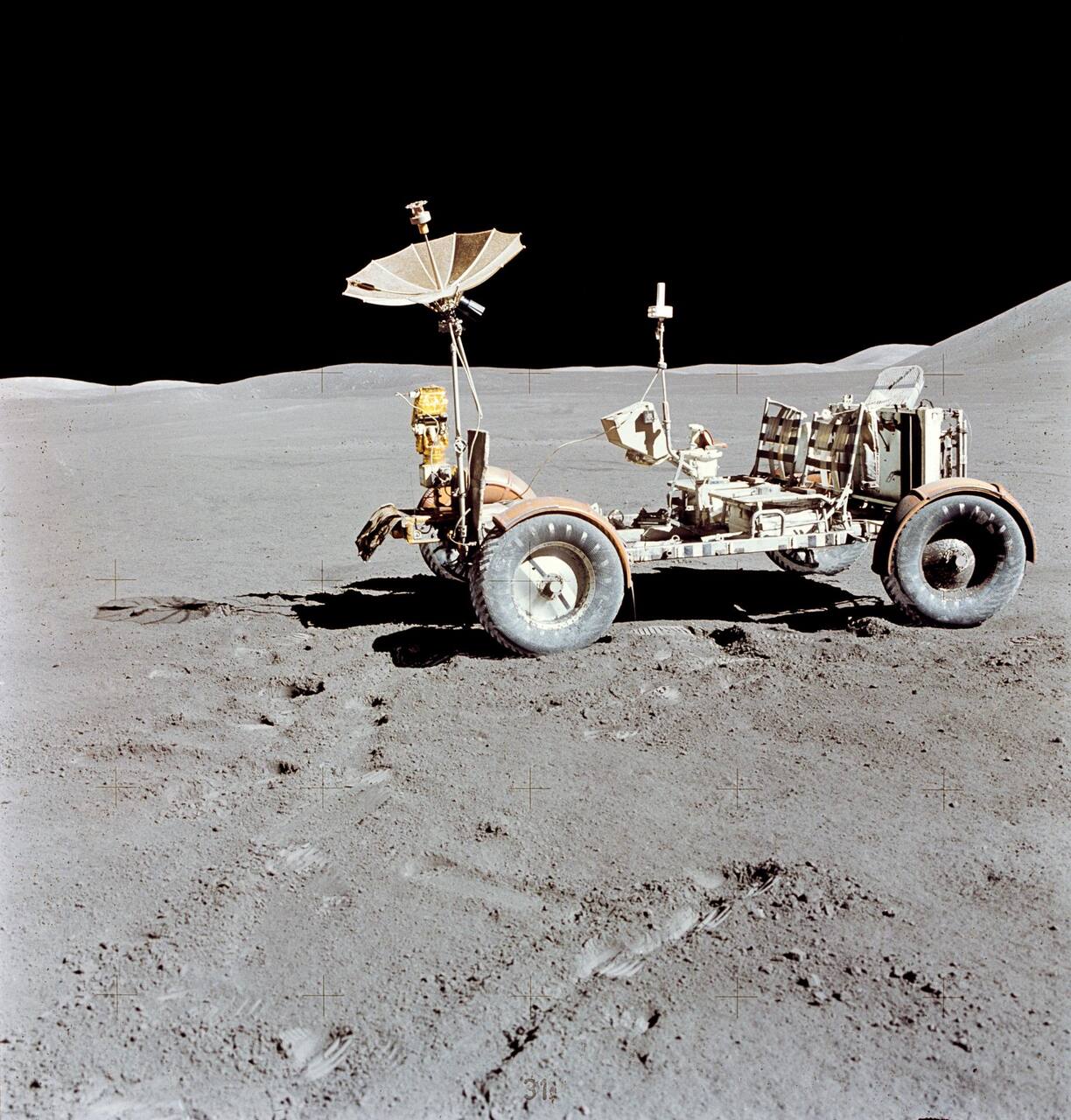 NASA. Public domain (NASA / US government work).
The problem
Section titled “The problem”A crewed lunar vehicle has to carry two suited astronauts and a payload over unconsolidated regolith in vacuum, at one-sixth gravity and with no recovery service, and it has to fit folded into one quadrant of a lander. The LRV was stowed in lunar module quadrant 1 at 1.78 m wide, 1.65 m high and 0.94 m deep, folded to 50 percent of its length and 70 percent of its width [7]. The requirement was deployment in thermal vacuum within 15 minutes by crew in pressure suits, with the lunar module tilted up to 14.5 degrees on up to a 6 degree slope [10].
The soil the wheels run in is summarized for engineers in the Lunar Sourcebook [43]. The environment sets four further constraints. Pneumatic tires were rejected because a puncture is unrecoverable and rubber degrades under ultraviolet and vacuum, and rigid rims because of ride quality [6]. Thermal control had to be passive, because a lunar morning mission of about 78 hours narrows the band to 0 to 100 C but offers no heaters or active loop [12]. Navigation had no external reference, so heading and distance had to be integrated onboard [5]. Soil strength was known only from Surveyor scoops and the first Apollo boot and landing-gear imprints, so wheel design rested on simulant tests [19], [18].
The alternative of remote driving was tested before the decision. MSFC ground tests of remote driving gave a 3.7 km sortie of 5 hours at 0.68 km/h average against a 4.8 km/h maximum, with about 15 percent of the time spent driving and the rest studying terrain and fixing heading [14]. The LRV took the other branch, a crew driver in the loop, which removed the latency problem and left mobility, energy, navigation and thermal control as the engineering problems.
What has flown
Section titled “What has flown”Three vehicles flew, on Apollo 15 (launched 26 July 1971), Apollo 16 and Apollo 17, and all three were left on the Moon [1], [3]. Boeing was prime contractor, General Motors Defense Research Laboratories supplied the mobility system, and Marshall Space Flight Center managed the program [42].
Apollo 15. The vehicle drove 27.9 km in 3 hours 8 minutes at 9.2 km/h average over three traverses, consumed about 52 A-h of the 242 A-h available at 1.87 A-h/km against a preflight prediction of 3.67, and showed an average track depth near 1 cm that matched terrestrial simulant predictions [1]. The deployment saddle bound because the lunar module sat tilted 11 degrees and the vehicle had been moved sideways before release [10]. Front steering was dead through the first traverse and returned after the crew cycled its switch and breaker. The report attributes it most probably to motor or gear train binding and leaves it open [1]. On rear steering alone the rear wheels slid into the objects the driver was avoiding, and at least once the vehicle rotated through 180 degrees [1]. Battery 2 had not cooled enough for its radiator cover to close by the second EVA, which the mission report attributes to dust on the mirrors.
Apollo 16. The vehicle drove 26.7 km (4.2, 11.1 and 11.4 km), reached 14 km/h on level ground, negotiated slopes estimated at up to 20 degrees and used 98.2 A-h [2]. Crew switch errors twice removed rear drive power and navigation displays, both cleared by restoring the configuration, and the forward wheels dug in when climbing without rear drive [2]. The right rear fender extension was knocked off, after which dust from that wheel covered the crew, the console and the communications equipment. Battery 2 reached 143 F by the close of the third EVA [2]. A rear steering anomaly was traced to an open circuit in the hand controller potentiometer or its wiring. A candidate mechanism, wiper open-circuiting below minus 58 C from congealed lubricant, did not explain the flights because neither vehicle fell below minus 5 C, and no corrective action was taken [4].
Apollo 17. The vehicle recorded 36.0 km of odometer distance in 253.5 minutes of drive time, an energy rate of 1.59 A-h/km, wander plus slip of 6 to 10 percent, zero navigation closure error at the lunar module on all three EVAs, and a crew-reported maximum of 18 km/h downhill [3]. The fender extension was lost again before the first traverse, battery power-up temperatures were 95 and 110 F against 80 F predicted, and the battery 2 indication failed off-scale low at the start of the third EVA, most probably a shorted thermistor from electrolyte leaking through the sensor bond [3].
Design and performance as flown
Section titled “Design and performance as flown”Each wheel is independently driven. The carcass is woven from 800 strands of 0.838 mm zinc-coated piano wire over a spun aluminum hub, with a titanium inner frame 64.8 cm in diameter acting as a bump stop that engages at 600 N radial load and 8.26 cm deflection and carries 4000 N ultimate [9]. Chevron titanium treads cover about 50 percent of the contact circumference [7]. Nominal contact pressure at 254 N radial load is 4.14 kPa. Chevron coverage of 50 percent gave the lowest power at the self-propelled point with the highest drawbar pull at 20 percent slip [9]. The 25 degree slope requirement needs 59.5 percent slip on average, rising to 84.5 percent at three standard deviations of the simulant fit [9].
Five candidate wheels were compared in fine sand before selection. Slope climbing was 28 to 30 degrees for the Bendix wheel and 15 to 20 degrees for the Boeing-GM and Grumman wheels, and single-wheel predictions of vehicle slope capability ran 1 to 2 degrees conservative [8]. Wheel performance was characterized at the US Army Engineer Waterways Experiment Station in a ground-basalt simulant at densities LSS1 to LSS5, reported as pull coefficient, torque coefficient and power number against slip [7], [15]. In that simulant, pull, torque and power number were effectively independent of wheel speed from 0.44 to 3.14 m/s, which the report attributes to soil momentum and air pore pressure canceling. Because the Moon has no pore air, the authors concluded LRV wheels could be more efficient at speed in flight than in the laboratory [15].
Flight results were better than prediction. Apollo 15 wheel sinkage averaged 1.25 cm at the 2.3 percent slip used to calibrate the odometer, and predicted energy consumption exceeded measured values by about 30 percent at the median because the flown soil was firmer than the design case [7]. The Surveyor 3 and 7 soil model, a slightly cohesive sand near 1.5 g/cm3 with 0.7 kN/m2 cohesion and 35 to 37 degrees friction angle, reproduced the measured Apollo 16 and 17 energy use [18]. Slopes encountered were 0 to 12, 0 to 18 and 0 to 20 degrees on the three missions, against an estimated capability of 19 to 23 degrees [18].
Suspension is a pair of parallel triangular arms per wheel reacting into a torsion bar, giving 35.6 cm ground clearance loaded and 43 cm unloaded [1]. Steering is double Ackermann with independent front and rear rack-and-pinion assemblies and a 3.05 m minimum turn radius, so a single steering failure degrades rather than ends mobility [7], [1].
Power is two non-rechargeable silver-zinc batteries of nominally 36 V and 120 A-h, about 64 kg [1], [12]. Energy was never the limit: the binding constraint was the walk-back distance on backpack life support, so the 120 km range capability was never approached [5]. Regenerative braking was rejected, since analysis showed it would return under 2 percent of energy [12]. The sealed traction drive is a series brush motor on an 80:1 harmonic drive in dry nitrogen with Krytox 143AZ lubricant [11].
The avionics are analog. Hand controller potentiometers feed pulse-width modulators, motor current is limited to 22 A, and a signal processing unit does the dead reckoning [12]. Distance comes from odometer pickups at nine pulses per wheel revolution, with the third fastest wheel driving the distance increment so that a dragging or spinning wheel contributes nothing [5]. Apollo 15 closed its three traverses at 0, 100 and 200 m with a maximum position error near 0.3 km [1]. Apollo 16 and 17 held 100 m maximum position error on every traverse [5]. A field qualification before flight had shown a 30 km traverse closing to better than 2 percent only with a temperature-controlled gyro and periodic sun-compass updates [5]. Hazard detection was visual: 1 m craters were not detectable until the front wheels were within 2 to 3 m [1].
The LRV carried the Lunar Communications Relay Unit, which gave a direct S-band link to Earth and a ground-pointed television camera [1]. It was a carrier for the hand tool carrier, drill, cameras and sample containers rather than an instrument platform, though wheel tracks and penetrometer readings made it a soil mechanics instrument: 5.97 lb/in2 per inch of gradient in the upper 2 cm of a track against 2.98 beside it [7].
Dust and heat
Section titled “Dust and heat”Passive thermal control stores heat in fusible masses while driving and rejects it to space while parked, through radiators with dust covers [1]. Dust on the mirrors defeats this. Apollo 15 battery temperatures rose from 68 and 78 F at second-EVA activation to 108 and 113 F at the end of the third, and the crew judged that the covers did not seal against their Velcro edges and that a small amount of dust precludes cool-down [1]. The loss of a fender extension on Apollo 16 and 17 coupled the dust problem to the thermal one [2], [3].
What is being tried now
Section titled “What is being tried now”The LRV’s direct descendants are the Lunar Terrain Vehicle contracts. In May 2026 NASA announced Phase 1 task orders to Astrolab (about 219 million dollars) and Lunar Outpost (220 million dollars) for crewed and uncrewed mobility by 2028 [21]. Neither vehicle has flown. Astrolab’s CLV-1 is adapted from the FLEX design and is stated at 950 kg and 10 km/h on level ground by the vendor, against about 2000 pounds and more than 6 mph in NASA’s release [20], [21]. Lunar Outpost’s Pegasus is stated at over 9 mph, a one-year operating life and manual, autonomous or teleoperated driving [21]. FLEX has articulating limbs that level the chassis and change ground clearance, a removable standing crew interface, and a sun-pointed solar array that stows during dynamic operations [22]. Moving power generation to a stowable array addresses the radiator dust problem the LRV exposed. NASA’s requirements for the vehicle are 15 km/h on flat terrain, 20 degree slopes, 30 cm obstacles, 800 kg payload and survival through 150 hours of darkness [29]. Canada’s lunar rover is a planned 42 kg, 0.4 cubic meter vehicle [38].
Wheels. The LRV wire-mesh wheel remains the reference [29]. Venturi’s hyper-deformable wheel for FLEX is a proposal stated as a duty cycle of 15 km/h, 1000 km and minus 240 to 130 C under a two tonne vehicle, announced without test results [23]. A continuously variable grouser-height wheel was tested on a linear gantry in 750 trials across rock, gravel and sand, with slip reduced 30 to 58 percent against fixed grousers; this is a laboratory result [24]. Bayesian co-optimization of wheel geometry and steering gains in continuum soil simulation was checked against three printed wheels and took 5 to 9 days for 3000 simulations, against 96 days for a prior discrete element single-wheel study; it has not left the laboratory [25]. The VIPER wheel, 500 mm with 24 grousers, was qualified over 40 km, twice its 20 km requirement; the rover did not fly [29], [44].
Predicting mobility in 1/6 g. The LRV program relied on dimensionless simulant data and Bekker-type models [15], [9]. Parabolic flight tests of a single wheel and cone penetrometer put the cone index gradient in 1 g at about four times its value in lunar gravity at identical density; granular scaling laws predicted lunar-gravity performance with errors of 2.7 to 8.5 percent, in the conservative direction, while matching cone index in 1 g gave 44 percent error in drawbar pull [27]. A discrete element study compares the scaling laws with reduced-weight and equal-mass tests against direct 1/6 g simulation and keeps scaling error under 5 percent at three wheel conditions in simulation only [26]. A magnetic levitation rig measured a 29.1 percent drop in cone penetration resistance at 1/6 g in 40 percent relative density simulant and 8.8 percent at 76 percent, so the gravity effect depends on density [28]. A drop tower study of granular settling reached 2.5 s of microgravity per flight [41]. NASA’s consolidated test practice uses the Lunar Terrain Vehicle as its case study [29]. A conceptual design tool for sub-50 kg lunar rovers evaluates a mission in about 30 ms and shows 24 to 27 percent drawbar pull error against published wheel data; it has no flight data [30].
Instrumented mobility. The LRV’s tracks and penetrometer readings were read as soil data after the fact [18]. VIPER was designed to do this in flight: a torque transducer in each suspension joint (plus or minus 297 N m) and an encoded wheel rim give normal force and sinkage, and a ground slip estimator was 93 percent accurate across 99 tests [32]. Its intended products were bearing capacity and shear strength [33]. The rover was not launched.
Learned slip, locomotion and control. The LRV estimated slip as a fixed 2.3 percent odometry bias [1]. A proposed replacement fuses wheel-slip classifiers from earlier lunar rovers with a small post-landing calibration set, trained on about 9000 simulated samples [31]. A reinforcement-learning controller on the ERNEST 75 kg rover with an actively articulated suspension cut cost of transport on a 20 degree dry sand slope to 13.4 from 21.3 mWh/(m kg) for a passive bogie, in ground tests [40]. None has flown.
Autonomy and operations. The LRV had no autonomous function. A one-tonne rover running lidar teach and repeat carried cargo between a simulated lander and habitat over two weeks at the CSA Analogue Terrain, with 0.10 m path tracking error [34]. The MEXEC planner drove the half-scale ERNEST 4.1 km in 5.2 hours in an October 2025 field test as a step toward the Endurance rover concept [35]. A model-based mode estimator for Endurance’s power subsystem has been exercised in simulation [36]. JAXA’s LEV-2, released from SLIM in January 2024, drove autonomously on the Moon, moving about 0.13 m [37]. A VIPER loop heat pipe tested in thermal vacuum at one sixth g tilt showed conductance rising from 0.5 to 20.4 W/K as load rose from 40 to 254 W [39].
The numbers
Section titled “The numbers”| Quantity | Apollo 15 | Apollo 16 | Apollo 17 |
|---|---|---|---|
| Distance, odometer | 27.9 km [1] | 26.6 km [5] | 34.8 km [5] |
| Distance, mission report | 27.9 km [1] | 26.7 km [2] | 36.0 km [3] |
| Energy consumed | 52 A-h of 242 [1] | 98.2 A-h of 242 [2] | 1.59 A-h/km [3] |
| Maximum speed | 9 to 13 km/h range [7] | 14 km/h [2] | 18 km/h [3] |
| Slopes encountered | 0 to 12 degrees [18] | 0 to 18 degrees [18] | 0 to 20 degrees [18] |
| Navigation position error limit | 600 m [5] | 100 m [5] | 100 m [5] |
| Parameter | Value | Source |
|---|---|---|
| Deployed length x width x height | 3.05 x 2.13 x 1.14 m | [7], [1] |
| Vehicle mass | about 206 kg | [1] |
| Wheel diameter x width | 81.3 x 22.9 cm | [9] |
| Ground clearance, loaded / unloaded | 35.6 / 43 cm | [1] |
| Minimum turn radius | 3.05 m | [7], [1] |
| Estimated maximum slope capability | 19 to 23 degrees | [18] |
| Design slope requirement | 25 degrees | [9] |
| Range capability | 120 km | [12] |
| Total distance, three vehicles | 89.3 km | [5] |
What is not established
Section titled “What is not established”Apollo 15 energy use is a reconstruction: the amp-hour indicator initially read 105 A-h instead of 121 for reasons never established and the battery 2 volt/ammeter was dead for the whole mission [1]. The front steering failure cause is stated only as most likely motor or gear train binding, and the anomaly is open. Apollo 15 track depth is a crew and photographic estimate.
Apollo 16 distances are approximate, slopes are crew estimates, and the battery 1 amp-hour integrator read about four times true usage from midway through the second traverse [2]. The Apollo 17 thermistor cause is the most probable one, not a confirmed one, the 18 km/h maximum is a crew report, and the performance table is degraded OCR [3]. The 19 to 23 degree slope capability is an estimate, not a flown limit [18]. The 25 degree requirement rests on a simulant slip fit [9], and the navigation accuracy figures are specification values [5].
The wheel, scaling, learning and planning results listed under current work are ground, simulation or analog-site results, and none has been checked against a crewed-vehicle traverse on the Moon. The two reduced-gravity soil results disagree in emphasis: parabolic flight put the cone index gradient at about a quarter of its 1 g value [27], while the magnetic levitation rig found the gravity effect shrinking as density rises [28]. Both used simulants weaker than measured Apollo soil [27]. The LTV masses and speeds are vendor and agency targets for unbuilt hardware [21]. The LRV remains the only soft-soil model check against a real extraterrestrial drive of this scale, and the south pole has no standard simulant to extend it [29]. Lunokhod comparisons, dust fender test results and the Wong-Reece stress model are not covered because their sources are not cited here.
References
- NASA Manned Spacecraft Center. (1971). Apollo 15 Mission Report
. NASA Manned Spacecraft Center, MSC-05161. Source
BibTeX
@techreport{anon1971apollo, title = {Apollo 15 Mission Report}, author = {{NASA Manned Spacecraft Center}}, number = {MSC-05161}, institution = {NASA Manned Spacecraft Center}, year = {1971}, url = {https://ntrs.nasa.gov/citations/19720021182}, abstract = {A detailed discussion is presented of the Apollo 15 mission, which conducted exploration of the moon over longer periods, greater ranges, and with more instruments of scientific data acquisition than previous missions. The topics include trajectory, lunar surface science, inflight science and photography, command and service module performance, lunar module performance, lunar surface operational equipment, pilot's report, biomedical evaluation, mission support performance, assessment of mission objectives, launch phase summary, anomaly summary, and vehicle and equipment descriptions. The capability of transporting larger payloads and extending time on the moon were demonstrated. The ground-controlled TV camera allowed greater real-time participation by earth-bound personnel. The crew operated more as scientists and relied more on ground support team for systems monitoring. The modified pressure garment and portable life support system provided better mobility and extended EVA time. The lunar roving vehicle and the lunar communications relay unit were also demonstrated.} } - (1972). Apollo 16 Mission Report
. NASA, NASA-TM-. Source
BibTeX
@techreport{anon1972apollo, title = {Apollo 16 Mission Report}, number = {NASA-TM-}, institution = {NASA}, year = {1972}, url = {https://ntrs.nasa.gov/citations/19720026127}, abstract = {Information is provided on the operational and engineering aspects of the Apollo 16 mission. Customary units of measurement are used in those sections of the report pertaining to spacecraft systems and trajectories. The International System of Units is used in sections pertaining to science activities.} } - MIssion Evaluation Team. (1973). Apollo 17 Mission Report
. NASA, NASA-TM-. Source
BibTeX
@techreport{anon1973apollo, title = {Apollo 17 Mission Report}, author = {{MIssion Evaluation Team}}, number = {NASA-TM-}, institution = {NASA}, year = {1973}, url = {https://ntrs.nasa.gov/citations/19730015117}, abstract = {Operational and engineering aspects of the Apollo 17 mission are outlined. The vehicle configuration was similar to those of Apollo 15 and 16. There were significant differences in the science payload for Apollo 17 and spacecraft hardware differences and experiment equipment are described. The mission achieved a landing in the Taurus-Littrow region of the moon and returned samples of the pre-Imbrium highlands and young craters.} } - (1973). Apollo 16 mission anomaly report no. 10: Rear steering inoperative
. NASA, NASA-TM-. Source
BibTeX
@techreport{anon1973apollob, title = {Apollo 16 mission anomaly report no. 10: Rear steering inoperative}, number = {NASA-TM-}, institution = {NASA}, year = {1973}, url = {https://ntrs.nasa.gov/citations/19730012137}, abstract = {The report by the Apollo 16 crew that the lunar roving vehicle rear steering was inoperative during the initial drive from the vehicle's deployment site was investigated. The malfunction, and the steering system are described. It is concluded that an open circuit occurred either in the hand controller potentiometer or between the potentiometer wiper and the summing node.} } - Smith, E. C. and Mustin, W. C. (1973). Lunar Roving Vehicle Navigation System Performance Review
. NASA, NASA-TN-. Source
BibTeX
@techreport{anon1973lunar, title = {Lunar Roving Vehicle Navigation System Performance Review}, author = {Smith, Earnest C. and Mustin, William C.}, number = {NASA-TN-}, institution = {NASA}, year = {1973}, url = {https://ntrs.nasa.gov/citations/19740003321}, abstract = {The design and operation of the lunar roving vehicle (LRV) navigation system are briefly described. The basis for the premission LRV navigation error analysis is explained and an example included. The real time mission support operations philosophy is presented. The LRV navigation system operation and accuracy during the lunar missions are evaluated.} } - Asnani, V., Delap, D. and Creager, C. (2009). The Development of Wheels for the Lunar Roving Vehicle
. Journal of Terramechanics, NASA/TM-2009-215798, 20100000019. Source
BibTeX
@article{asnani2009development, title = {The Development of Wheels for the Lunar Roving Vehicle}, author = {Asnani, Vivake and Delap, Damon and Creager, Colin}, journal = {Journal of Terramechanics}, volume = {46}, number = {NASA/TM-2009-215798, 20100000019}, pages = {89-103}, institution = {NASA Glenn Research Center}, year = {2009}, doi = {10.1016/j.jterra.2009.02.005}, abstract = {The Lunar Roving Vehicle (LRV) was developed for NASA s Apollo program so astronauts could cover a greater range on the lunar surface, carry more science instruments, and return more soil and rock samples than by foot. Because of the unique lunar environment, the creation of flexible wheels was the most challenging and time consuming aspect of the LRV development. Wheels developed for previous lunar systems were not sufficient for use with this manned vehicle; therefore, several new designs were created and tested. Based on criteria set by NASA, the choices were narrowed down to two: the wire mesh wheel developed by General Motors (GM), and the hoop spring wheel developed by the Bendix Corporation. Each of these underwent intensive mechanical, material, and terramechanical analyses, and in the end, the wire mesh wheel was chosen for the LRV. Though the wire mesh wheel was determined to be the best choice for its particular application, it may be insufficient towards achieving the objectives of future lunar missions that could require higher tractive capability, increased weight capacity, or extended life. Therefore lessons learned from the original LRV wheel development and suggestions for future Moon wheel projects are offered.} } - Costes, N. C., Farmer, J. E. and George, E. B. (1972). Mobility Performance of the Lunar Roving Vehicle: Terrestrial Studies --- Apollo 15 Results
. Conference of the International, NASA TR R-401, 19730008090. Source
BibTeX
@inproceedings{costes1972mobility, title = {Mobility Performance of the Lunar Roving Vehicle: Terrestrial Studies --- Apollo 15 Results}, author = {Costes, Nicholas C. and Farmer, John E. and George, Edwin B.}, booktitle = {Conference of the International}, number = {NASA TR R-401, 19730008090}, institution = {NASA Marshall Space Flight Center}, address = {Stockholm and Kiruna}, month = {12}, year = {1972}, url = {https://ntrs.nasa.gov/citations/19730008090}, abstract = {The constriants of the Apollo 15 mission dictated that the average and limiting performance capabilities of the first manned lunar roving vehicle be known or estimated within narrow margins. Extensive studies were conducted and are compared with the actual performance of the lunar roving vehicle during the Apollo 15 mission. From this comparison, conclusions are drawn relating to the capabilities and limitation of current terrestrial methodology in predicting the mobility performance of lunar roving vehicles under in-situ environmental conditions, and recommendations are offered concerning the performance of surface vehicles on future missions related to lunar or planetary exploration.} } - Freitag, D. R., Green, A. J. and Melzer, K.-J. (1970). Performance Evaluation of Wheels for Lunar Vehicles (Summary Report)
. U.S. Army Engineer Waterways Experiment Station, Technical Report M-70-2. Source
BibTeX
@techreport{freitag1970performance, title = {Performance Evaluation of Wheels for Lunar Vehicles (Summary Report)}, author = {Freitag, Dean R. and Green, Andrew J. and Melzer, Klaus-Jurgen}, number = {Technical Report M-70-2}, institution = {U.S. Army Engineer Waterways Experiment Station}, year = {1970}, url = {https://ntrs.nasa.gov/citations/19700027358}, abstract = {Performance evaluation of lunar surface vehicle wheels in fine sand} } - Green, A. J. and Melzer, K.-J. (1971). Performance of Boeing LRV wheels in a lunar soil simulant. Report 1: Effect of wheel design and soil
. U.S. Army Engineer Waterways Experiment Station, Technical Report M-71-10, Report 1. Source
BibTeX
@techreport{green1971performance, title = {Performance of Boeing LRV wheels in a lunar soil simulant. Report 1: Effect of wheel design and soil}, author = {Green, Andrew J. and Melzer, Klaus-Jurgen}, number = {Technical Report M-71-10, Report 1}, institution = {U.S. Army Engineer Waterways Experiment Station}, year = {1971}, url = {https://erdc-library.erdc.dren.mil/handle/11681/29961} } - Hunter, A. B. and Spacey, B. W. (1972). Lunar roving vehicle deployment mechanism
. Aerospace Mechanisms Symposium, 19730010149. Source
BibTeX
@inproceedings{hunter1972lunar, title = {Lunar roving vehicle deployment mechanism}, author = {Hunter, A. B. and Spacey, B. W.}, booktitle = {Aerospace Mechanisms Symposium}, number = {19730010149}, institution = {NASA}, year = {1972}, url = {https://ntrs.nasa.gov/citations/19730010149}, abstract = {The space support equipment that supports the lunar roving vehicle during the flight to the moon and permits the vehicle to be deployed from the lunar module onto the lunar surface with a minimum amount of astronaut participation is discussed. The design and evolution of the equipment are reviewed. The success of the overall lunar roving vehicle design, including the space support equipment, was demonstrated on the Apollo 15 and 16 missions.} } - Jones, C. S. J., Nola, F. J. and Doran, B. J. (1969). Traction drive system design considerations for a lunar roving vehicle
. SAE Technical Paper Series, NASA-TM-. Source
BibTeX
@inproceedings{jones1969traction, title = {Traction drive system design considerations for a lunar roving vehicle}, author = {Jones, C. S., Jr. and Nola, F. J. and Doran, B. J.}, booktitle = {SAE Technical Paper Series}, volume = {1}, number = {NASA-TM-}, institution = {NASA}, year = {1969}, doi = {10.4271/700023}, abstract = {<div class="htmlview paragraph">For an optimum design, the weight, energy consumption, and operational flexibility of the traction drive system for a lunar roving vehicle must be considered along with the power supply, motor, and power train.</div> <div class="htmlview paragraph">Other problems considered in this paper include: environment and motor dissipation; motor type (a-c or d-c) and commutation if d-c; motor controller (switching of large currents); delivery of torque at varying speeds; the power train; use of regenerative braking and conservation of energy; and power supply voltage variation. These problems are studied in the light of certain general system specifications, which fall into weight, performance, and environment categories. Tradeoff studies are considered for purposes of optimization in each of these areas.</div> <div class="htmlview paragraph">Special consideration is given to the controller and system design as it pertains to regenerative braking and the conservation of energy. Some aspects of changing the modes of motor operation to satisfy extreme performance requirements of speed and torque are discussed.</div>} } - Jones, C. S. J. and Nola, F. J. (1971). Mobility systems activity for lunar rovers at MSFC
. NASA, NASA-TM-. Source
BibTeX
@techreport{jones1971mobility, title = {Mobility systems activity for lunar rovers at MSFC}, author = {Jones, C. S., Jr. and Nola, F. J.}, number = {NASA-TM-}, institution = {NASA}, year = {1971}, url = {https://ntrs.nasa.gov/citations/19720004516}, abstract = {The Apollo Lunar Roving Vehicle (LRV) mobility system is described. Special emphasis is given to the redundancy aspects and to the selection of the drive motors. A summary chart of the performance on the lunar surface during the Apollo 15 flight is included. An appendix gives details on some development work on high efficiency drive systems and compares these systems to the selected system.} } - Mastin, W. C., White, P. R. and Vintz, F. L. (1971). Remote control and navigation tests for application to long-range lunar surface exploration
. Navigation, NASA-TM-. Source
BibTeX
@article{mastin1971remote, title = {Remote control and navigation tests for application to long-range lunar surface exploration}, author = {Mastin, W. C. and White, P. R. and Vintz, F. L.}, journal = {Navigation}, volume = {19}, number = {NASA-TM-}, pages = {42-60}, institution = {NASA}, year = {1971}, doi = {10.1002/j.2161-4296.1972.tb00125.x}, abstract = {NAVIGATION is a quarterly journal published by the Institute of Navigation. The journal publishes original, peer-reviewed articles on all aspects of positioning, navigation, and timing. The journal also publishes selected technical notes and survey articles, as well as papers of exceptional quality drawn from the Institute’s conference proceedings.} } - Melzer, K.-J. (1971). Performance of the Boeing LRV wheels in a lunar soil simulant. Report 2: Effects of speed, Wheel load, and soil
. U.S. Army Engineer Waterways Experiment Station, NASA-CR-129612. Source
BibTeX
@techreport{melzer1971performance, title = {Performance of the Boeing LRV wheels in a lunar soil simulant. Report 2: Effects of speed, Wheel load, and soil}, author = {Melzer, Klaus-Jurgen}, number = {NASA-CR-129612}, institution = {U.S. Army Engineer Waterways Experiment Station}, year = {1971}, url = {https://ntrs.nasa.gov/citations/19730004536}, abstract = {Two nearly identical Boeing-GM wire-mesh Lunar Roving Vehicle (LRV) wheels were laboratory tested in a lunar soil simulant to determine the influence of wheel speed and acceleration, wheel load, presence of a fender, travel direction, and soil strength on the wheel performance. Constant-slip and three types of programmed-slip tests were conducted with a single-wheel dynamometer system. Test results indicated that performance of single LRV wheels in terms of pull coefficient, power number, and efficiency were not influenced by wheel speed and acceleration, travel direction, the presence of a fender, or wheel load. Of these variables, only load influenced sinkage, which increased with increasing load. For a given slip, the pull coefficient and power number increased with increasing soil strength. However, for a given pull coefficient or slope, slip was less in firmer soil; thus, the power number decreased and efficiency increased with increasing soil strength.} } - Mitchell, J. K., Carrier, W. D. I., Costes, N. C., Houston, W. N., Scott, R. F. and Hovland, H. J. (1974). Apollo soil mechanics experiment S-200
. NASA, NASA-CR-134306. Source
BibTeX
@techreport{mitchell1974apollo, title = {Apollo soil mechanics experiment S-200}, author = {Mitchell, James K. and Carrier, W. D., III and Costes, Nicholas C. and Houston, William N. and Scott, Ronald F. and Hovland, H. John}, number = {NASA-CR-134306}, institution = {NASA}, year = {1974}, url = {https://ntrs.nasa.gov/citations/19740019219}, abstract = {The physical and mechanical properties of the unconsolidated lunar surface material samples that were obtained during the Apollo missions were studied. Sources of data useful for deduction of soil information, and methods used to obtained the data are indicated. A model for lunar soil behavior is described which considers soil characteristics, density and porosity, strength, compressibility, and trafficability parameters. Lunar history and processes are considered, and a comparison is made of lunar and terrestrial soil behavior. The impact of the findings on future exploration and development of the moon are discussed, and publications resulting from lunar research by the soil mechanics team members are listed.} } - NASA. (1969). Apollo 11 Preliminary Science Report
. NASA Manned Spacecraft Center, NASA SP-214. Source
BibTeX
@techreport{nasa1969apollo11,
  title = {{Apollo 11} Preliminary Science Report},
  author = {{NASA}},
  number = {NASA SP-214},
  institution = {NASA Manned Spacecraft Center},
  year = {1969},
  url = {https://ntrs.nasa.gov/citations/19700000726},
  abstract = {Preliminary scientific observation of Apollo 11 mission}
}
Further reading
- Kaufman, S. (1973). Equations of motion of the lunar roving vehicle. . Journal of Spacecraft and Rockets. Source
- Mitchell, J. K., Bromwell, L. G., Carrier, W. D. I., Costes, N. C., Houston, W. N. and Scott, R. F. (1972). Soil mechanics experiment . NASA. Source
- Mitchell, J. K., Carrier, W. D. I., Houston, W. N., Scott, R. F., Bromwell, L. G., Durgunoglu, H. T., Hovland, H. J., Treadwell, D. D. and Costes, N. C. (1972). Soil mechanics . NASA. Source