Viking Surface Sampler
Program pages NASA Science: Viking 1
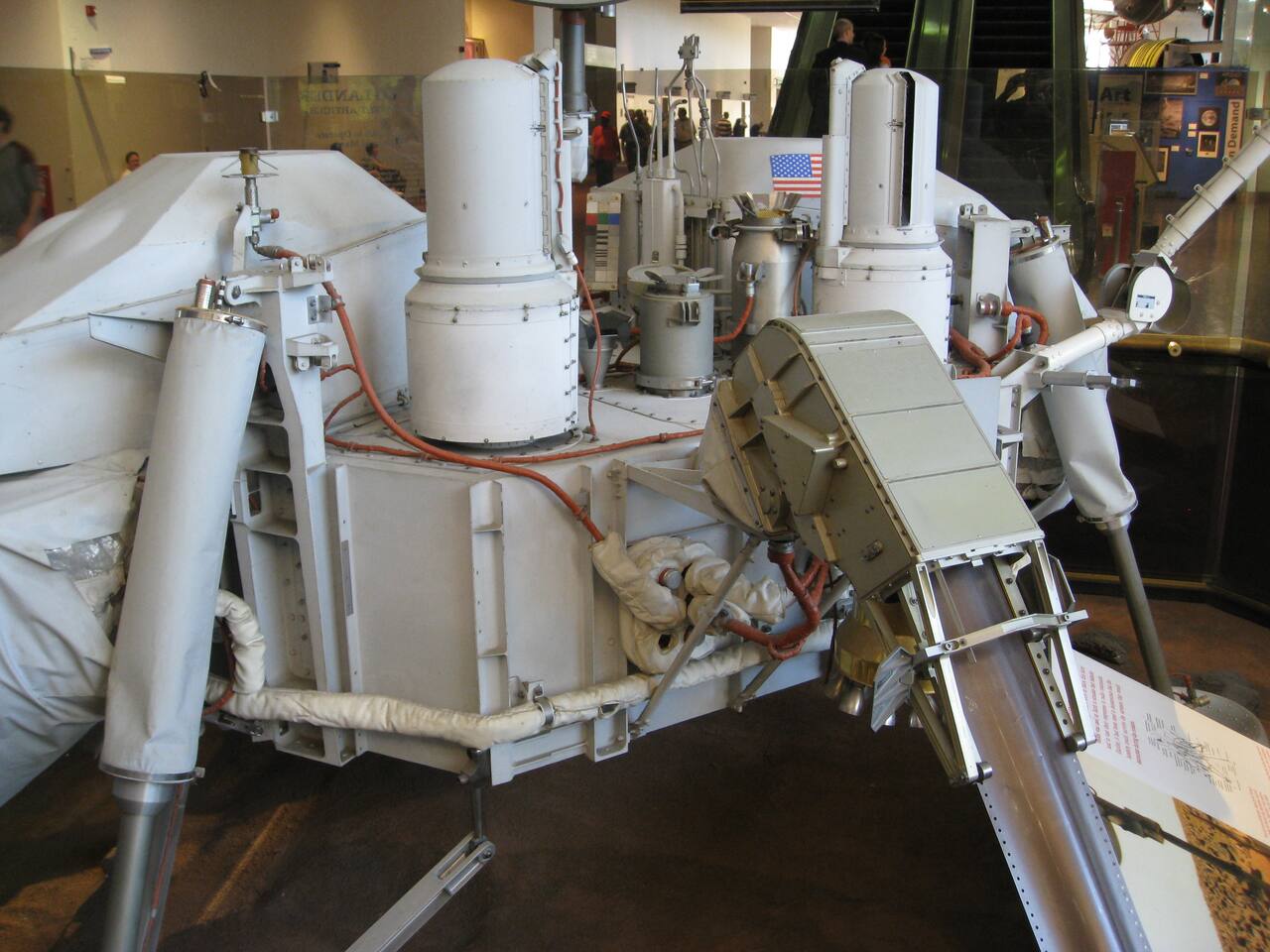 Source: brewbooks, via Wikimedia Commons; Creative Commons Attribution-ShareAlike license.
Overview
Section titled “Overview”A stationary lander on Mars cannot drive to a sample, and the Earth-Mars radio delay rules out driving a manipulator in real time. Whatever reached the surface material had to be commanded once, run a whole acquisition and delivery cycle from stored sequences, and survive doing so before the telemetry came back. The Viking Surface Sampler Subsystem was the first machine to acquire and process Martian samples for onboard analysis [29], [38]. Martin Marietta Aerospace built it under NASA Langley, and one flew on each of Viking Lander 1 and Viking Lander 2 in 1976 [37], [35].
The subsystem is more than a manipulator. It comprises the acquisition assembly, a furlable boom carrying a collector head, plus processing and distribution assemblies for the biology instrument and the gas chromatograph mass spectrometer (GCMS), and an electronics control assembly [37]. It also carried hardware for the physical properties and magnetic properties investigations [37], [36].
Design space and why the flown options converged
Section titled “Design space and why the flown options converged”Every landed sampler has to solve the same four problems: reach a patch of ground from a fixed deck, break the ground, condition the material to a particle size an instrument inlet accepts, and place it without contaminating or losing it. The flown solutions fall into five families.
Extendable scoop arms. Surveyor 3, 4 and 7 carried the Soil Mechanics/Surface Sampler, a scoop on a lazy-tongs linkage with elevation, azimuth, extension and scoop-door axes, the first robotic manipulator operated on another world [23]. It flew without force or position instrumentation, so the forces it exerted were inferred from imagery and, on one mission, motor current [23]. Viking replaced the linkage with a furlable tube boom, twelve feet of tape wound flat on a six inch drum that forms a column as it extends, which gave a 120 degree sample arc from 3 to 10 ft radius, about 90 sq ft of ground, from a stowed package that fit the deck [37].
Rigid-link articulated arms. The Mars Surveyor 2001 and MVACS back-hoe arm, a 4 DOF design with joint output torques of 26, 91, 53 and 10 N-m and an end effector force near 80 N, is the lineage of the Phoenix arm and of the InSight arm [9]. Phoenix flew a 2.4 m 4 DOF arm with a scoop, blades and a powered rasp for ice-cemented soil [10]. Over more than 150 sols the Phoenix arm ran 53 dig sequences across 10 trenching areas and delivered 18 samples, 6 to TEGA, 4 to the wet chemistry laboratory and 8 to the optical microscope [11]. The InSight arm placed instruments under flight software that expands sequences into via points, checks each against joint limits and collisions, and compensates link deflection [1]. The Mars Exploration Rover arm is a 5 DOF device whose 10 mm and 10 degree placement requirement was split with the front Hazcam stereo pair, giving the arm 5 mm and 5 degrees, verified on the ground only [5].
Arm plus drill turret. Curiosity combined an arm, a hard-material drill and a sieving and portioning chain on one turret. The drill is rotary-percussive with 120 N weight on bit and 1800 blows per minute [27], and the first 200 sols placed the sol 180 drill hole within about 2 to 3 mm of a target picked in a MAHLI image, a single measurement on one hole [28]. The Perseverance 5 DOF arm docks its Corer to a rotating dock ring that supplies the sixth degree of freedom, using Force-Corrected Docking with four posts and four alignment cones; only nine Mars dockings were on record when it was reported [12]. Its chuck is preloaded because brassboard coring with the 0.3 mm radial ball play of the MSL chuck gave unacceptable cores [3], and brassboard coring in a space simulator exposed core fragments mushrooming in the bit teeth [14].
Drills and penetrators for depth. A scoop reaches centimeters. The 1 m class Icebreaker drill, tested at Mars pressure and in the Antarctic Dry Valleys, reached technology readiness level 5, without launch or entry vibration testing [32]. The TRIDENT lunar drill reached the same field-test stage at Haughton Crater and the Bishop Tuff, where it choked in ice-cemented material [17]; in Antarctic boreholes its torque, weight on bit and penetration rate identified an ice-rock transition near 62 cm, in a version of the paper not peer reviewed [8]. The InSight HP3 mole is the flown counterexample: it reached 37 cm against a 3 to 5 m requirement because a cohesive duricrust gave no hull friction against hammer recoil [31]. No flown Mars sampler has reached meter depth.
Touch-and-go and teleoperated sampling. Where gravity is negligible, OSIRIS-REx avoided holding position at the surface with the gas-driven TAGSAM, qualified on the ground and on parabolic flights lasting 16 to 18 s [6]. The Chang’e-6 farside scooping used a binocular terrain model and point-cloud pose estimation; its 3.8 mm scooping depth error and 30 mm arm error were measured on an Earth testbed [13]. The Mars Sample Return transfer arm baseline that JPL documented was canceled, so its capability set is analysis and testbed work only [15].
The designs converged on a small number of choices for reasons the environment fixes. The lander envelope was itself unsettled: Mariner 69 showed Martian surface pressure to be 4 to 20 mbar rather than 80, which forced an aeroshell redesign [34]. The radio delay forces stored sequences. Instrument inlets set particle size: the Viking collector head sieve holes were 2 mm [33], and later inlets such as the SAM vibrated funnels receive sieved powder from the rover [26], and CheMin vibrates its cells in place of sample rotation [7]. The arm also became an imaging platform, as with the MAHLI camera on Curiosity [16].
What changed and what it enabled
Section titled “What changed and what it enabled”Viking had no measurement of its own for soil strength, so strength was inferred from the sampler, the landing and the lander; Surveyor and the Soviet lunar program had done the same on the Moon with a scoop, penetrometers and returned samples [23], [22], [24]. Later missions replaced inference by instrumentation and by telemetry. Phoenix used its own trenching and scraping as a soil-mechanics instrument, as the Viking backhoe had [11]. Curiosity derived terrain properties by inverting wheel imprints, sinkage and slip, and the resulting cohesion and friction angle are fits to simulation, not measurements [2]. Drill telemetry now serves the same purpose for subsurface horizons [8]. Planning also changed: Perseverance arm sequences are built from via points that a rover planner reviews by hand, and fewest-viapoints path simplification cut the mean from 3.86 to 1.08 [21]. The open actuator work is thermal: an oscillating heat pipe inside a sampling arm actuator is simulated only [25].
Specifications
Section titled “Specifications”| Parameter | Value | Source |
|---|---|---|
| Boom type | furlable tube boom, flattened on the drum, forms a column when extended | [37] |
| Boom stowed on drum | about 12 ft wound on a 6 in drum | [37] |
| Boom reach | 10 ft (3.0 m) | [35], [33] |
| Primary sample field | 120 degree arc, 3 ft minimum to 10 ft maximum radius, about 90 sq ft (8.4 m2) | [37] |
| Collector head | clamshell with sieve lid, 2 mm holes | [33] |
| Command interface | stored sequences from the lander guidance, control and sequencing computer | [37] |
Mission record
Section titled “Mission record”| Parameter | Value | Source |
|---|---|---|
| Lander 1 sampler sequences | 20 run, 17 successful, 12 samples delivered | [35] |
| Lander 2 sampler sequences | 28 run, 18 fully successful, 16 samples delivered | [35] |
| Lander 2 partial sequences | 9, all insufficient rock delivered to the XRFS | [35] |
| Lander 1 operating period | 20 July 1976 to 11 November 1982 | [38] |
Pre-flight, the lander system demonstration snagged the sampler arm on the holder of the magnet cleaning brush. The fix was a minor hardware change and a mission rule forbidding magnet cleaning until all biology samples were taken [34]. A boom motor item stayed on the program problem list from February 1973 to September 1974 [34]. The sampler hardware was also qualified on the KC-135 to reproduce reduced Martian gravity effects on the mechanism [37].
Flight anomalies
Section titled “Flight anomalies”Two boom no-go events on Lander 1, on sols 2 and 14, were traced to successive retract commands winding the furlable element tight on its storage drum [35]. The boom stores in a five to six sided shape rather than a circle, so its corners load the restraint brake shoes intermittently and the instantaneous starting torque exceeds the motor [35]. Frozen carbon dioxide and jammed surface material were ruled out because no slowly increasing motor load appeared in the current telemetry.
The fix was procedural: never issue successive extend or retract commands, and operate near peak sol temperature, a restriction later waived with no problems. A sol 18 diagnostic sequence exercised the boom in all six axes under close timing control [35].
A separate GCMS event on Lander 1 gave a false no-sample indication: less than 0.1 cc was needed for analysis but about 0.7 cc was needed to trip the level detector, so a full sample was not reported [35]. The Lander 1 mission ended when a faulty command from Earth ended communications on 11 November 1982 [38]. The lesson for any deployable boom manipulator is that a stored sequence with no real-time control needs its recovery paths designed in, and that stowed cross section is a design parameter, not a packaging detail [35].
Results returned
Section titled “Results returned”No Viking lander experiment was designed to measure physical properties, so the mechanical properties of the surface were inferred from touchdown dynamics, engine-exhaust erosion, sample trenches, surface-bearing tests, backhoe touchdowns and comminutor motor currents [36]. Three soil-like units were separated. Drift material is consistent with a bulk density of 1,200 kg/m3, a friction angle of 14 to 21 degrees and a cohesion of 0.7 to 3.0 kPa; blocky material with 1,600 kg/m3, 27 to 32 degrees and 1.5 to 16 kPa; crusty to cloddy material with about 1,400 kg/m3 [36]. Trench wall collapse in photographs resembled wet sand [33]. For the Moon, the corresponding Soviet laboratory and Lunokhod penetrometer record gives a porosity of 0.8 to 0.9, a bearing power near 0.35 to 0.40 kg/cm2, a cohesion of 0.04 to 0.06 kg/cm2 and a friction angle of 20 to 25 degrees [24]. Pre-Apollo simulant work showed that essentially every lunar geotechnical property is a strong function of bulk density, so a single density measurement does not settle a site [20], and the Apollo-era synthesis is drawn from six Apollo and three Luna sites near the equator [19].
Heritage
Section titled “Heritage”The furlable boom stayed unique. Every later landed Mars sampler uses a rigid arm [10], [27]. What carried forward was the collector pattern: a scoop for loose material, a harder-material tool beside it, a vibratory sieve in or after the tool, and instruments carried on the tool. Phoenix put a rasp in the back of the scoop [10]; Curiosity sieved and portioned material before delivery, and the SAM inlet receives that powder [26]. The NASA design-criteria compilation of 1982 told designers of such systems which environment to design against [30], and the pre-landing MSL description gives design values for the rover that carried the arm and drill, not Mars measurements [18]. The Scarab, a 280 kg rover built to drill to 1 m in lunar cold traps, was tested at Earth gravity only [4].
Flown on another body, with in-flight records: Surveyor scoops [23], Viking [35], Phoenix [11], MSL [28], InSight [1], Mars 2020 [12]. MER, OSIRIS-REx and Chang’e-6 hardware also flew, but the cited records give ground-test accuracy only [5], [6], [13]. Ground-tested only: Icebreaker [32], TRIDENT [17], the actuator heat pipe [25], and the canceled Mars Sample Return transfer arm [15].
What is not established
Section titled “What is not established”The Viking sampler literature is a performance record, not an analysis. The contractor report lists physical properties activities rather than values and tabulates almost none of the underlying torque, force and trench dimension figures in extractable form. The boom jamming mechanism is a design team hypothesis supported by consistent telemetry and by a similar failure in early testing, not a reproduced fault, and the temperature half of the fix was never shown to matter because the restriction was waived with no problem [35]. No soil property was measured directly: bulk density was never uniquely determined by any instrument, and the in situ values are inferences reconciled across dielectric constant, thermal inertia and simulant tests [36]. The pre-launch description reports no flight results, since it was written two years before launch [37]. The Ezell history chapters carry no engineering values and cannot be used for them [33], [34]. For later arms the same gap recurs: Phoenix flight operations quantify no placement accuracy or force [11], MER accuracy is a ground result with gravity droop compensated by model [5], and the Curiosity 2 to 3 mm figure is one measurement on one hole [28]. Depth sampling beyond 37 cm on Mars has no flown precedent [31].
References
- Ali, K. S. (2021). InSight Mars Lander Instrument Deployment Arm Flight Software
. IEEE Aerospace Conference. Source
BibTeX
@inproceedings{ali2021insight, title = {InSight Mars Lander Instrument Deployment Arm Flight Software}, author = {Ali, Khaled S.}, booktitle = {IEEE Aerospace Conference}, pages = {1-11}, address = {Big Sky, Montana}, year = {2021}, doi = {10.1109/aero50100.2021.9438296}, abstract = {The Interior Exploration using Seismic Investigations, Geodesy and Heat Transport (InSight) lander landed on Mars on November 26, 2018 and continues to investigate the internal structure of the planet two years later. The Instrument Deployment Arm (IDA), a robotic arm on the lander, was used to deploy the science instrument payloads from the lander deck to the surface of Mars and to take images of the lander and the surrounding environment. This was the first precision deployment and release by a robotic arm on another planet. After deploying the instruments, the IDA has been used for instrument commissioning, scientific data gathering, and to assist with troubleshooting one of the science instruments. This paper provides a high-level summary of the flight software that controls the IDA. The paper provides an overview of the IDA software interfaces, task structure, command handling strategy, motion specification, motion planning, motor control, grapple control, fault protection, and telemetry.} } - Arvidson, R. E., Bellutta, P., Calef, F., Fraeman, A. A., Garvin, J. B., Gasnault, O., Grant, J. A., Grotzinger, J. P., Hamilton, V. E., Heverly, M., Iagnemma, K. A., Johnson, J. R., Lanza, N., Le Mouelic, S., Mangold, N., Ming, D. W., Mehta, M., Morris, R. V., Newsom, H. E., Renno, N., Rubin, D., Scheiber, J., Sletten, R., Stein, N. T., Thuillier, F., Vasavada, A. R., Vizcaino, J. and Wiens, R. C. (2014). Terrain Physical Properties Derived from Orbital Data and the First 360 Sols of Mars Science Laboratory Curiosity Rover Observations in Gale Crater
. Journal of Geophysical Research: Planets, 20190002035. Source
BibTeX
@article{arvidson2014terrain, title = {Terrain Physical Properties Derived from Orbital Data and the First 360 Sols of Mars Science Laboratory Curiosity Rover Observations in Gale Crater}, author = {Arvidson, Raymond E. and Bellutta, Paolo and Calef, F. and Fraeman, Abigail A. and Garvin, James B. and Gasnault, Olivier and Grant, John A. and Grotzinger, John P. and Hamilton, Victoria E. and Heverly, M. and Iagnemma, K. A. and Johnson, Jeffrey R. and Lanza, Nina and Le Mouelic, S. and Mangold, N. and Ming, D. W. and Mehta, M. and Morris, Richard V. and Newsom, H. E. and Renno, N. and Rubin, David and Scheiber, J. and Sletten, R. and Stein, N. T. and Thuillier, Franck and Vasavada, Ashwin R. and Vizcaino, J. and Wiens, Roger C.}, journal = {Journal of Geophysical Research: Planets}, volume = {119}, number = {20190002035}, pages = {1322-1344}, institution = {NASA}, year = {2014}, doi = {10.1002/2013je004605}, abstract = {Abstract Physical properties of terrains encountered by the Curiosity rover during the first 360 sols of operations have been inferred from analysis of the scour zones produced by Sky Crane Landing System engine plumes, wheel touch down dynamics, pits produced by Chemical Camera (ChemCam) laser shots, rover wheel traverses over rocks, the extent of sinkage into soils, and the magnitude and sign of rover‐based slippage during drives. Results have been integrated with morphologic, mineralogic, and thermophysical properties derived from orbital data, and Curiosity‐based measurements, to understand the nature and origin of physical properties of traversed terrains. The hummocky plains (HP) landing site and traverse locations consist of moderately to well‐consolidated bedrock of alluvial origin variably covered by slightly cohesive, hard‐packed basaltic sand and dust, with both embedded and surface‐strewn rock clasts. Rock clasts have been added through local bedrock weathering and impact ejecta emplacement and form a pavement‐like surface in which only small clasts (<5 to 10 cm wide) have been pressed into the soil during wheel passages. The bedded fractured (BF) unit, site of Curiosity's first drilling activity, exposes several alluvial‐lacustrine bedrock units with little to no soil cover and varying degrees of lithification. Small wheel sinkage values (<1 cm) for both HP and BF surfaces demonstrate that compaction resistance countering driven‐wheel thrust has been minimal and that rover slippage while traversing across horizontal surfaces or going uphill, and skid going downhill, have been dominated by terrain tilts and wheel‐surface material shear modulus values.} } - Barletta, A. (2020). Design and Development of a Robust Chuck Mechanism for the Mars2020 Coring Drill
. JPL Open Repository. Source
BibTeX
@inproceedings{barletta2020design, title = {Design and Development of a Robust Chuck Mechanism for the Mars2020 Coring Drill}, author = {Barletta, Anthony}, publisher = {JPL Open Repository}, year = {2020}, url = {https://dataverse.jpl.nasa.gov/dataset.xhtml?persistentId=hdl:2014/52360} } - Bartlett, P., Wettergreen, D. and Whittaker, W. L. (2008). Design of the Scarab Rover for Mobility and Drilling in the Lunar Cold Traps
. International Symposium on Artificial Intelligence, Robotics and Automation in Space. Source
BibTeX
@inproceedings{bartlett2008design, title = {Design of the Scarab Rover for Mobility and Drilling in the Lunar Cold Traps}, author = {Bartlett, Paul and Wettergreen, David and Whittaker, William L.}, booktitle = {International Symposium on Artificial Intelligence, Robotics and Automation in Space}, address = {Los Angeles, California}, year = {2008}, url = {https://www.ri.cmu.edu/pub_files/2008/2/08isairas.scarab.bartlett.pdf} } - Baumgartner, E. T., Bonitz, R. G., Melko, J. P., Shiraishi, L. R. and Leger, P. C. (2005). The Mars Exploration Rover Instrument Positioning System
. IEEE Aerospace Conference. Source
BibTeX
@inproceedings{baumgartner2005mars, title = {The {Mars Exploration Rover} Instrument Positioning System}, author = {Baumgartner, Eric T. and Bonitz, Robert G. and Melko, Joseph P. and Shiraishi, Lori R. and Leger, P. Chris}, booktitle = {IEEE Aerospace Conference}, pages = {1--19}, address = {Big Sky, Montana}, year = {2005}, doi = {10.1109/aero.2005.1559295}, abstract = {During Mars Exploration Rover (MER) surface operations, the scientific data gathered by the in situ instrument suite has been invaluable with respect to the discovery of a significant water history at Meridiani Planum and the hint of water processes at work in Gusev Crater. Specifically, the ability to perform precision manipulation from a mobile platform (i.e., mobile manipulation) has been a critical part of the successful operation of the Spirit and Opportunity rovers. As such, this paper describes the MER instrument positioning system that allows the in situ instruments to operate and collect their important science data using a robust, dexterous robotic arm combined with visual target selection and autonomous software functions.} } - Bierhaus, E. B., Clark, B. C., Harris, J. W., Payne, K. S., Dubisher, R. D., Wurts, D. W., Hund, R. A., Kuhns, R. M., Linn, T. M., Wood, J. L., May, A. J., Dworkin, J. P., Beshore, E., Lauretta, D. S. and the OSIRIS-REx Team. (2018). The OSIRIS-REx Spacecraft and the Touch-and-Go Sample Acquisition Mechanism (TAGSAM)
. Space Science Reviews, 7. Source
BibTeX
@article{bierhaus2018osiris, title = {The {OSIRIS-REx} Spacecraft and the Touch-and-Go Sample Acquisition Mechanism ({TAGSAM})}, author = {Bierhaus, Edward B. and Clark, Benton C. and Harris, J. W. and Payne, K. S. and Dubisher, R. D. and Wurts, D. W. and Hund, R. A. and Kuhns, R. M. and Linn, T. M. and Wood, J. L. and May, A. J. and Dworkin, Jason P. and Beshore, E. and Lauretta, Dante S. and {the OSIRIS-REx Team}}, journal = {Space Science Reviews}, volume = {214}, number = {7}, pages = {107}, year = {2018}, doi = {10.1007/s11214-018-0521-6}, abstract = {The Origins, Spectral-Interpretation, Resource-Identification, Security and Regolith-Explorer (OSIRIS-REx) spacecraft supports all aspects of the mission science objectives, from extensive remote sensing at the asteroid Bennu, to sample collection and return to Earth. In general, the success of planetary missions requires the collection, return, and analysis of data, which in turn depends on the successful operation of instruments and the host spacecraft. In the case of OSIRIS-REx, a sample-return mission, the spacecraft must also support the acquisition, safe stowage, and return of the sample. The target asteroid is Bennu, a B-class near-Earth asteroid roughly 500 m diameter. The Lockheed Martin-designed and developed OSIRIS-REx spacecraft draws significant heritage from previous missions and features the Touch-and-Go-Sample-Acquisition-Mechanism, or TAGSAM, to collect sample from the surface of Bennu. Lockheed Martin developed TAGSAM as a novel, simple way to collect samples on planetary bodies. During short contact with the asteroid surface, TAGSAM releases curation-grade nitrogen gas, mobilizing the surface regolith into a collection chamber. The contact surface of TAGSAM includes “contact pads”, which are present to collect surface grains that have been subject to space weathering. Extensive 1-g laboratory testing, “reduced-gravity” testing (via parabolic flights on an airplane), and analysis demonstrate that TAGSAM will collect asteroid material in nominal conditions, and a variety of off-nominal conditions, such as the presence of large obstacles under the TAGSAM sampling head, or failure in the sampling gas firing. TAGSAM, and the spacecraft support of the instruments, are central to the success of the mission.} } - Blake, D., Vaniman, D., Achilles, C., Anderson, R., Bish, D., Bristow, T., Chen, C., Chipera, S., Crisp, J., Des Marais, D., Downs, R. T., Farmer, J., Feldman, S., Fonda, M., Gailhanou, M., Ma, H., Ming, D. W., Morris, R. V., Sarrazin, P., Stolper, E., Treiman, A. and Yen, A. (2012). Characterization and Calibration of the CheMin Mineralogical Instrument on Mars Science Laboratory
. Space Science Reviews. Source
BibTeX
@article{blake2012characterization, title = {Characterization and Calibration of the CheMin Mineralogical Instrument on Mars Science Laboratory}, author = {Blake, David and Vaniman, David and Achilles, Cherie and Anderson, Robert and Bish, David and Bristow, Tom and Chen, Curtis and Chipera, Steve and Crisp, Joy and Des Marais, David and Downs, Robert T. and Farmer, Jack and Feldman, Sabrina and Fonda, Mark and Gailhanou, Marc and Ma, Hongwei and Ming, Doug W. and Morris, Richard V. and Sarrazin, Philippe and Stolper, Ed and Treiman, Allan and Yen, Albert}, journal = {Space Science Reviews}, volume = {170}, pages = {341--399}, year = {2012}, doi = {10.1007/978-1-4614-6339-9_12}, abstract = {A principal goal of the Mars Science Laboratory (MSL) rover Curiosity is to identify and characterize past habitable environments on Mars. Determination of the mineralogical and chemical composition of Martian rocks and soils constrains their formation and alteration pathways, providing information on climate and habitability through time. The CheMin X-ray diffraction (XRD) and X-ray fluorescence (XRF) instrument on MSL will return accurate mineralogical identifications and quantitative phase abundances for scooped soil samples and drilled rock powders collected at Gale Crater during Curiosity’s 1-Mars-year nominal mission. The instrument has a Co X-ray source and a cooled charge-coupled device (CCD) detector arranged in transmission geometry with the sample. CheMin’s angular range of 5 ∘ to 50 ∘ 2 θ with <0.35 ∘ 2 θ resolution is sufficient to identify and quantify virtually all minerals. CheMin’s XRF requirement was descoped for technical and budgetary reasons. However, X-ray energy discrimination is still required to separate Co K α from Co K β and Fe K α photons. The X-ray energy-dispersive histograms (EDH) returned along with XRD for instrument evaluation should be useful in identifying elements Z >13 that are contained in the sample. The CheMin XRD is equipped with internal chemical and mineralogical standards and 27 reusable sample cells with either Mylar ® or Kapton ® windows to accommodate acidic-to-basic environmental conditions. The CheMin flight model (FM) instrument will be calibrated utilizing analyses of common samples against a demonstration-model (DM) instrument and CheMin-like laboratory instruments. The samples include phyllosilicate and sulfate minerals that are expected at Gale crater on the basis of remote sensing observations.} } - Boelter, S., Brown, G., Stucky, T., Temesgen, E., Mai, R., Weber, L., Gini, M., Bergman, D., Fortuin, C., Glass, B. and Wilhelm, M. (2026). TRIDENT Drill Performance and Subsurface Fault and Anomaly Detection in Antarctic Environments
. Annals of Glaciology. Source
BibTeX
@article{boelter2026trident, title = {TRIDENT Drill Performance and Subsurface Fault and Anomaly Detection in Antarctic Environments}, author = {Boelter, Sarah and Brown, Greta and Stucky, Thomas and Temesgen, Ebasa and Mai, Rene and Weber, Lucas and Gini, Maria and Bergman, Dean and Fortuin, Carter and Glass, Brian and Wilhelm, Marybeth}, journal = {Annals of Glaciology}, year = {2026}, url = {https://ntrs.nasa.gov/citations/20260007172}, abstract = {The Regolith and Ice Drill for Exploring New Terrain (TRIDENT), a 1-meter rotary percussive drill developed by Honeybee Robotics, is designed for extraterrestrial subsurface exploration. Because extraterrestrial drilling cannot rely on prior subsurface characterization or direct human operation, adaptive state estimation and anomaly detection are necessary for reliable autonomous drilling. We evaluate TRIDENT’s drilling performance in planetary analog environments during fieldwork in Schirmacher Oasis and Lake Untersee, Antarctica, including cold-desert permafrost terrain, glacially smoothed rock, ice-covered surfaces, subsurface frozen boundary layers, and ice-rock transitions representative of planetary subsurfaces. This paper investigates subsurface fault and anomaly detection methods for planetary drilling with minimal prior training data while further characterizing TRIDENT’s operational performance across representative analog terrains.} } - Bonitz, R., Slostad, J., Bon, B., Braun, D., Brill, R., Buck, C. W., Fleischner, R., Haldeman, A., Herman, J., Hertzel, M., Noon, D. E., Pixler, G., Schenker, P., Ton, T., Tucker, C. and Zimmerman, W. (2000). MVACS Robotic Arm
. JPL Open Repository. Source
BibTeX
@inproceedings{bonitz2000mvacs, title = {MVACS Robotic Arm}, author = {Bonitz, R. and Slostad, J. and Bon, Bruce and Braun, D. and Brill, R. and Buck, Carl W. and Fleischner, Richard and Haldeman, A. and Herman, J. and Hertzel, M. and Noon, Don E. and Pixler, G. and Schenker, P. and Ton, T. and Tucker, Curtis and Zimmerman, Wayne}, publisher = {JPL Open Repository}, year = {2000}, url = {https://dataverse.jpl.nasa.gov/dataset.xhtml?persistentId=hdl:2014/13866} } - Bonitz, R. G., Shiraishi, L., Robinson, M., Arvidson, R. E., Chu, P. C., Wilson, J. J., Davis, K. R., Paulsen, G., Kusack, A. G., Archer, D. and Smith, P. (2008). NASA Mars 2007 Phoenix Lander Robotic Arm and Icy Soil Acquisition Device
. Journal of Geophysical Research: Planets. Source
BibTeX
@article{bonitz2008nasa, title = {NASA Mars 2007 Phoenix Lander Robotic Arm and Icy Soil Acquisition Device}, author = {Bonitz, Robert G. and Shiraishi, Lori and Robinson, Matthew and Arvidson, Raymond E. and Chu, P. C. and Wilson, J. J. and Davis, K. R. and Paulsen, G. and Kusack, A. G. and Archer, Doug and Smith, Peter}, journal = {Journal of Geophysical Research: Planets}, volume = {113}, pages = {E00A01}, publisher = {American Geophysical Union (AGU)}, year = {2008}, doi = {10.1029/2007je003030}, abstract = {The primary purpose of the Mars 2007 Phoenix Lander Robotic Arm (RA) and associated Icy Soil Acquisition Device (ISAD) is to acquire samples of Martian dry and icy soil (DIS) by digging, scraping, and rasping, and delivering them to the Thermal Evolved Gas Analyzer and the Microscopy, Electrochemistry, and Conductivity Analyzer. The RA will also position (1) the Thermal and Electrical Conductivity Probe (TECP) in the DIS; (2) the TECP at various heights above the surface for relative humidity measurements, and (3) the Robotic Arm Camera to take images of the surface, trench, DIS samples within the ISAD scoop, magnetic targets, and other objects of scientific interest within its workspace. The RA/ISAD will also be used to generate DIS piles for monitoring; conduct DIS scraping, penetration, rasping, and chopping experiments; perform compaction tests; and conduct trench cave‐in experiments. Data from the soil mechanics experiments will yield information on Martian DIS properties such as angle of repose, cohesion, bearing strength, and grain size distribution.} } - Bonitz, R., Shiraishi, L., Robinson, M., Carsten, J., Volpe, R., Trebi-Ollennu, A., Arvidson, R. E., Chu, P. C., Wilson, J. J. and Davis, K. R. (2009). The Phoenix Mars Lander Robotic Arm
. IEEE Aerospace Conference. Source
BibTeX
@inproceedings{bonitz2009phoenix, title = {The Phoenix Mars Lander Robotic Arm}, author = {Bonitz, Robert and Shiraishi, Lori and Robinson, Matthew and Carsten, Joseph and Volpe, Richard and Trebi-Ollennu, Ashitey and Arvidson, Raymond E. and Chu, P. C. and Wilson, J. J. and Davis, K. R.}, booktitle = {IEEE Aerospace Conference}, pages = {1-12}, organization = {Jet Propulsion Laboratory, California Institute of Technology}, address = {Big Sky, Montana}, year = {2009}, doi = {10.1109/aero.2009.4839306}, abstract = {The Phoenix Mars Lander Robotic Arm (RA) has operated for 149 sols since the Lander touched down on the north polar region of Mars on May 25, 2008. During its mission it has dug numerous trenches in the Martian regolith, acquired samples of Martian dry and icy soil, and delivered them to the Thermal Evolved Gas Analyzer (TEGA) and the Microscopy, Electrochemistry, and Conductivity Analyzer (MECA). The RA inserted the Thermal and Electrical Conductivity Probe (TECP) into the Martian regolith and positioned it at various heights above the surface for relative humidity measurements. The RA was used to point the Robotic Arm Camera to take images of the surface, trenches, samples within the scoop, and other objects of scientific interest within its workspace. Data from the RA sensors during trenching, scraping, and trench cave-in experiments have been used to infer mechanical properties of the Martian soil. This paper describes the design and operations of the RA as a critical component of the Phoenix Mars Lander necessary to achieve the scientific goals of the mission.} } - Brooks, S., Townsend, J., Collins, C., Carsten, J., Frost, M., Reid, J., Robinson, M. and Warner, A. (2022). Docking the Mars 2020 Perseverance Robotic Arm
. IEEE Aerospace Conference. Source
BibTeX
@inproceedings{brooks2022docking, title = {Docking the Mars 2020 Perseverance Robotic Arm}, author = {Brooks, Sawyer and Townsend, Julie and Collins, Curtis and Carsten, Joseph and Frost, Matthew and Reid, Jason and Robinson, Matthew and Warner, Antonia}, booktitle = {IEEE Aerospace Conference}, pages = {1-12}, address = {Big Sky, Montana}, year = {2022}, doi = {10.1109/aero53065.2022.9843517} } - Chen, C., Jia, X., Zhang, G., Zheng, Y., Deng, X. and Qu, Y. (2025). Vision-based sampling implementation in the Chang'e-6 lunar farside sample return mission
. Light: Advanced Manufacturing, 10. Source
BibTeX
@article{chen2025vision, title = {Vision-based sampling implementation in the Chang'e-6 lunar farside sample return mission}, author = {Chen, Congjia and Jia, Xiaoyu and Zhang, Gao and Zheng, Yanhong and Deng, Xiangjin and Qu, Yufu}, journal = {Light: Advanced Manufacturing}, volume = {6}, number = {10}, pages = {1}, year = {2025}, doi = {10.37188/lam.2025.010}, abstract = {Lunar sample return missions are crucial for researching the composition and origin of the Moon. In recent decades, several lunar sample return missions have been conducted, yielding abundant and valuable lunar samples. As the latest development in lunar sample returns, the Chang’e-6 mission aimed to implement lunar farside sampling. The shorter time available for sampling requires higher sampling efficiency. In this study, the main factors in the sampling site selection and sampling process are introduced and a vision-based sampling implementation is designed for the Chang’e-6 mission to significantly simplify manual operation while maintaining high sampling quality. By sufficiently leveraging the point cloud data reconstructed from the binocular camera images, autonomous terrain analysis and sample point selection are achieved. A 6D pose estimation pipeline based on point cloud registration provides a robust method for sampler pose measurement, replacing the previous manual fine-tuning process and achieving better accuracy. Owing to the well-analyzed sample points and accurate fine-tuning, the proposed approach demonstrates high accuracy in controlling the scooping depth, while significantly reducing the time cost of the sampling implementation, effectively supporting the Chang’e-6 lunar sample mission.} } - Chu, L. E., Brown, K. M. and Kriechbaum, K. (2017). Mars 2020 Sampling and Caching Subsystem Environmental Development Testing and Preliminary Results. doi.org/10.1109/aero.2017.7943564
BibTeX
@misc{chu2017mars, title = {Mars 2020 Sampling and Caching Subsystem Environmental Development Testing and Preliminary Results}, author = {Chu, Lauren E. and Brown, Kyle M. and Kriechbaum, Kristo}, howpublished = {Presentation at the IEEE Aerospace Conference}, pages = {1-10}, year = {2017}, doi = {10.1109/aero.2017.7943564}, abstract = {The Environmental Development Testing program supported the development test efforts of the Mars 2020 Sampling and Caching Subsystem from May to November 2015. The engineering prototype Brassboard Corer was attached to a five degree-of-freedom robotic arm to execute a 96-test matrix of ambient and low pressure tests in the 10 ft. thermal vacuum chamber at the NASA Jet Propulsion Laboratory, California Institute of Technology. The Pretest, Test, and Post Test procedures are described, and some preliminary results are discussed. Data and observations from this test campaign inform the future development of the software and hardware toward the Mars 2020 flight design, including the next iteration of the rock coring drill, the Engineering Development Unit Corer.} } - Dolci, M., Bowkett, J., Bailey, P., Boettcher, A., Kim, J., Rogers, P., Pham, T.-H., Chavez Clemente, D., Shatts, J., Townsend, J., Twu, P. and Collins, C. (2025). Robotics Capabilities Development for Mars Sample Return Transfer Activities
. IEEE Aerospace Conference. Source
BibTeX
@inproceedings{dolci2025robotics, title = {Robotics Capabilities Development for Mars Sample Return Transfer Activities}, author = {Dolci, Marco and Bowkett, Joseph and Bailey, Philip and Boettcher, Anna and Kim, Junggon and Rogers, Preston and Pham, Tu-Hoa and Chavez Clemente, Daniel and Shatts, Jennifer and Townsend, Julie and Twu, Philip and Collins, Curtis}, booktitle = {IEEE Aerospace Conference}, pages = {1-25}, address = {Big Sky, Montana}, year = {2025}, doi = {10.1109/aero63441.2025.11068463}, abstract = {The planned NASA-European Space Agency (ESA) Mars Sample Return campaign aims to be the first set of missions to bring Martian samples back to Earth, where thousands of scientists would make groundbreaking discoveries that could redefine our understanding of the Red Planet and perhaps even the origins of life on Earth. A crucial component of the circa 2023 baseline design for the missions was the transfer of sample tubes from the Martian surface to the ascent vehicle, which requires a highly dexterous robotic arm and sophisticated control strategies. Development and testing of the control algorithms were underway at NASA's Jet Propulsion Laboratory on advanced R&D testbeds, while the ESA is responsible for delivering the flight robotic arm. To meet the complex requirements for transferring the sample tubes, we propose an abstract layer consisting of three important robotics capabilities, each to be implemented for the first time in planetary exploration. 1. 7-DoF Manipulation: This capability focuses on managing the kinematics of the 7-DoF robotic arm. It includes the development of algorithms for forward and inverse kinematics, joint redundancy management, kinematic calibration, deflection compensation, target-to-pose selection, trajectory generation, and control strategies for single-joint, multi-joint, Cartesian motions, and free-space closed-loop control. 2. Robotics Vision: This capability pertains to a monocular vision system mounted on the robotic arm's end-effector with an additional redundant camera. These cameras are essential for localizing the Mars 2020 rover (M2020) tube-retrieval station, the SRL OS, identifying tubes on the Martian surface, and estimating the robotic arm's pose to ensure successful interactions with the station. 3. In-Contact Manipulation: This capability addresses the robot's interaction with its external environment. It involves load estimation using a 6-DoF force-torque sensor, force regulation (standard load-wrench control to a setpoint), and hybrid motion (force regulation orthogonal to a baseline velocity). This paper documents for posterity the infusion of these robotics capabilities, including the requirements, analysis, and testing processes that would have been necessary to ensure the success of the circa 2023 SRL Sample Transfer System design.} } - Edgett, K. S., Yingst, R. A., Ravine, M. A., Caplinger, M. A., Maki, J. N., Ghaemi, F. T., Schaffner, J. A., Bell, I. J. F., Edwards, L. J., Herkenhoff, K. E., Heydari, E., Kah, L. C., Lemmon, M. T., Minitti, M. E., Olson, T. S., Parker, T. J., Rowland, S. K., Schieber, J., Sullivan, R. J., Sumner, D. Y., Thomas, P. C., Jensen, E. H., Simmonds, J. J., Sengstacken, A. J., Willson, R. G. and Goetz, W. (2012). Curiosity's Mars Hand Lens Imager (MAHLI) Investigation
. Space Science Reviews. Source
BibTeX
@article{edgett2012curiosity, title = {Curiosity's Mars Hand Lens Imager (MAHLI) Investigation}, author = {Edgett, Kenneth S. and Yingst, R. Aileen and Ravine, Michael A. and Caplinger, Michael A. and Maki, Justin N. and Ghaemi, F. Tony and Schaffner, Jacob A. and Bell, III, James F. and Edwards, Laurence J. and Herkenhoff, Kenneth E. and Heydari, Ezat and Kah, Linda C. and Lemmon, Mark T. and Minitti, Michelle E. and Olson, Timothy S. and Parker, Timothy J. and Rowland, Scott K. and Schieber, Juergen and Sullivan, Robert J. and Sumner, Dawn Y. and Thomas, Peter C. and Jensen, Elsa H. and Simmonds, John J. and Sengstacken, Aaron J. and Willson, Reg G. and Goetz, Walter}, journal = {Space Science Reviews}, volume = {170}, pages = {259--317}, year = {2012}, doi = {10.1007/978-1-4614-6339-9_10}, abstract = {The Mars Science Laboratory (MSL) Mars Hand Lens Imager (MAHLI) investigation will use a 2-megapixel color camera with a focusable macro lens aboard the rover, Curiosity, to investigate the stratigraphy and grain-scale texture, structure, mineralogy, and morphology of geologic materials in northwestern Gale crater. Of particular interest is the stratigraphic record of a ∼5 km thick layered rock sequence exposed on the slopes of Aeolis Mons (also known as Mount Sharp). The instrument consists of three parts, a camera head mounted on the turret at the end of a robotic arm, an electronics and data storage assembly located inside the rover body, and a calibration target mounted on the robotic arm shoulder azimuth actuator housing. MAHLI can acquire in-focus images at working distances from ∼2.1 cm to infinity. At the minimum working distance, image pixel scale is ∼14 μm per pixel and very coarse silt grains can be resolved. At the working distance of the Mars Exploration Rover Microscopic Imager cameras aboard Spirit and Opportunity, MAHLI’s resolution is comparable at ∼30 μm per pixel. Onboard capabilities include autofocus, auto-exposure, sub-framing, video imaging, Bayer pattern color interpolation, lossy and lossless compression, focus merging of up to 8 focus stack images, white light and longwave ultraviolet (365 nm) illumination of nearby subjects, and 8 gigabytes of non-volatile memory data storage.} } - Glass, B., Stoker, C., Battah, H., Boelter, S., Fortuin, C., King, I., Stevenson, T. and Stucky, T. (2024). TRIDENT Drill Validation at Mars and Lunar Analog Field Sites
. Lunar and Planetary Science Conference. Source
BibTeX
@inproceedings{glass2024trident, title = {{TRIDENT} Drill Validation at Mars and Lunar Analog Field Sites}, author = {Glass, Brian and Stoker, Carol and Battah, Hussein and Boelter, S. and Fortuin, C. and King, I. and Stevenson, T. and Stucky, T.}, booktitle = {Lunar and Planetary Science Conference}, year = {2024}, url = {https://ntrs.nasa.gov/citations/20240000585}, abstract = {Drilling on Earth is typically a human-intensive activity. Drilling on other planets is further complicated by the lack of prior local field surveys of their target area, hence blindly drilling into uncertain target rocks. Field conditions on the Moon or Mars are also different than for shallow drilling on Earth: lower temperatures and pressures, less power available, low masses (hence less weight-on-bit). Given the cost of transport from Earth, no drilling muds or working fluids are likely to be available to carry away cuttings. And impact-gardened regolith and dust vary mechanically and texturally from most terrestrial soils. The Regolith and Ice Drill for Exploration of New Terrains (TRIDENT) is a rotary-percussive 1m-class drill from Honeybee Robotics. It is low-power (rotary and percussive actuators are 200 W each) and lightweight (<20 kg) with the maximum weight on bit limited to 200 N. TRIDENT has been manifested for the Volatiles Investigating Polar Exploration Rover (VIPER) and PRIME-1 lunar south pole missions in 2024, has previously been field tested at a hot, dry analog site in the Atacama Desert, and in lunar conditions in thermal vacuum chamber tests. TRIDENT was also part of the 2019 Icebreaker Mars Discovery proposal, as well as in the Mars Life Explorer concept. During ARADS tests, drill control and fault recovery automation software enabled hands-off operations of a rover-mounted TRIDENT drill. TRIDENT Drill Analog Site Validation: Past TRIDENT tests in thermal vacuum (TVAC) chambers targeted containers of manufactured lunar simulants with added volatiles. 2022 TRIDENT ambient testing at NASA Ames drilled into cemented lunar simulant materials. Low cuttings-permeability led to cuttings buildup, and drill choking and binding was observed. The Atacama analog site in ARADS had desiccated unconsolidated sediments that did not challenge the TRIDENT design. However, lunar polar regolith is expected to be diverse and heterogeneous with varying clast sizes, with abundant impactites and perhaps subsurface ice deposits. Neither the simulants nor Atacama testing had completely covered the TRIDENT-targeted field characteristics, motivating further analog tests prior to the planned lunar missions. To gain more insight into the behavior of the TRIDENT hardware in diverse impactites and subsurface ice, and to verify the software automation in that environment, in August 2023 TRIDENT was brought to Haughton Crater, a field analog site in the Canadian Arctic. In September 2023 the same drill was brought to the Bishop Tuff in southern California to verify whether drilling binding behaviors previously seen in lunar simulant testing would be observed in naturally occurring fine-grained massive layers. The ~22 Ma Haughton Crater impact structure is located at 75 ̊22’ N, 89 ̊41’ W, on northwestern Devon Island, Nunavut, Canada. Numerous deposits of pale-grey crater-fill polymictic impact-melt breccia are found within the crater with a typical thickness reaching ~125 m or greater and covering ~60 km<sup>-2</sup>. An approximately 600m-thick permafrost layer is also present with ice typically found within 0.5-0.6m of the surface. The volcanic tableland north of Bishop, CA exposes densely welded tuff laid down during the eruption that created the Long Valley Caldera at approximately 0.76 Ma. Extensional faults and the Owens River gorge expose cross-sections across the plateau. The area is viewed as an analog site for Mars features believed to be of pyroclastic origin. Results: Haughton Crater.Drilling tests were conducted 8-13 August 2023 at a previously undisturbed area separated 5-10 m from past years’ Drill Hill test sites (75.4208, -089.7613). In six days, TRIDENT drilled 8 holes to nearly 1 m depth each, totaling 7.80 m. The active layer/ice boundary was at ~67 cm depth, with a total of approximately 2.4 m drilled into ice or ice-cemented impact breccia. During drilling, five drill fault states were observed and successfully recovered. Holes 23-1, 4 and 7 were drilled under manual control, using Honeybee’s Thorax user interface. Holes 23-5, 6, and 8 were drilled with the Ames IBexec automated drilling control software. TRIDENT was observed to have little difficulty in the thawed uncemented impact breccia above the active layer boundary, but required percussion to make slower headway in the ice-cemented breccia. In Hole 23-7 (Fig.1), drilling slowed down in a massive unit just above the active-layer boundary (perhaps a large rock extending into the ice-cementation?), with only 7cm progress made in 27 minutes of high auger torque and constant percussion, leading to a choking fault and then a binding fault. A similar pattern had been observed in TRIDENT Rio Tinto test data from 2017 [6] as well as in the 2022laboratory tests.Bishop Tuff.A team from NASA Ames and the US Geological Survey deployed the same TRIDENT drill to Bishop Sites 1B and 1C (37.4203, -118.4289; 37.4265, -118.4215) on 13-16 September 2023, on the Bishop Tuff plateau. A third drill site was used 17-18 September 2023(37.4598, -118.3667) in an abandoned pumice mine. Four holes (totaling 2.5m depth) were drilled into the fine-grained, meters-thick tuff units at Sites 1B and 1C, and a further two boreholes (totaling 1.98m depth) were made at the pumice site. Drill behavior in the tuff below 10 cm depth was similar to that seen at 65-74 cm depth in Haughton Hole 23-7 (Fig. 1) and that seen in the 2022 lab simulant drilling. Drill safety torque limits were exceeded multiple times resulting in drill stops downhole. These freezes then required external added torques (with a pipe wrench) to resume rotation, to unstick the drill for withdrawal. To prevent this choking and binding behavior we found that more-frequent cuttings removal was necessary, e.g., reducing the “drill bite” size from the nominal 10 cm to 2 cm per bite --bringing the auger up to the surface more frequently, as seen in Bishop Site 1C Hole 2 (Fig.2). This permitted slow progress without drill binding and without external interventions. Conversely, TRIDENT drilling in the more porous pumice target material showed no cuttings buildup issue, and single bites as large as 40 cm were demonstrated. Discussion: We observed that TRIDENT easily penetrated unconsolidated heterogeneous soils (both above the active layer boundary at Haughton and previously in the Atacama). Cemented or consolidated targets that were cuttings-permeable (icy impact breccia, pumice) required more energy applied and percussion. However, in non-cuttings-permeable targets (welded microporous tuff, cemented simulants, boulder) TRIDENT was observed to be prone to excessive cuttings accumulation leading to choking/binding faults and stalling. The wedge cutting bit, used by TRIDENT in field tests and in its flight versions, pulverizes the target rock and creates fine cuttings that ideally are transported up the auger spirals for removal. In porous, fractured or vesicular target materials (such as at the Bishop pumice site) a significant portion of the cuttings are pushed aside, but for non-fractured, microporous targets the cuttings remain in the borehole and accumulate. Rock powder is relatively incompressible as a working fluid at only 100-200N downward force (TRIDENT limits) and hence eventual drilling progress slows or stops. Our recommended strategy for improving TRIDENT cuttings removal in massive target units with low cuttings-permeability is to reduce TRIDENT bite sizes when encountering these units, from 10cm to as little as 1-2cm, to effectively bail the accumulating cuttings. This approach was demonstrated to reduce choking and allowed slow progress to continue in cuttings-impermeable microporous target units (viz. the Bishop tuff in our September 2023 tests or cemented simulants in 2022 ambient tests). } } - Grotzinger, J. P., Crisp, J., Vasavada, A. R., Anderson, R. C., Baker, C. J., Barry, R., Blake, D. F., Conrad, P., Edgett, K. S., Ferdowski, B., Gellert, R., Gilbert, J. B., Golombek, M., Gómez-Elvira, J., Hassler, D. M., Jandura, L., Litvak, M., Mahaffy, P., Maki, J., Meyer, M., Malin, M. C., Mitrofanov, I., Simmonds, J. J., Vaniman, D., Welch, R. V. and Wiens, R. C. (2012). Mars Science Laboratory Mission and Science Investigation
. Space Science Reviews. Source
BibTeX
@article{grotzinger2012mars, title = {Mars Science Laboratory Mission and Science Investigation}, author = {Grotzinger, John P. and Crisp, J. and Vasavada, Ashwin R. and Anderson, R. C. and Baker, C. J. and Barry, R. and Blake, David F. and Conrad, P. and Edgett, Kenneth S. and Ferdowski, B. and Gellert, Ralf and Gilbert, J. B. and Golombek, M. and Gómez-Elvira, J. and Hassler, Donald M. and Jandura, Louise and Litvak, Maxim and Mahaffy, P. and Maki, J. and Meyer, M. and Malin, Michal C. and Mitrofanov, Igor and Simmonds, John J. and Vaniman, D. and Welch, R. V. and Wiens, Roger C.}, journal = {Space Science Reviews}, volume = {170}, pages = {5--56}, year = {2012}, doi = {10.1007/978-1-4614-6339-9_3}, abstract = {Scheduled to land in August of 2012, the Mars Science Laboratory (MSL) Mission was initiated to explore the habitability of Mars. This includes both modern environments as well as ancient environments recorded by the stratigraphic rock record preserved at the Gale crater landing site. The Curiosity rover has a designed lifetime of at least one Mars year (∼23 months), and drive capability of at least 20 km. Curiosity’s science payload was specifically assembled to assess habitability and includes a gas chromatograph-mass spectrometer and gas analyzer that will search for organic carbon in rocks, regolith fines, and the atmosphere (SAM instrument); an x-ray diffractometer that will determine mineralogical diversity (CheMin instrument); focusable cameras that can image landscapes and rock/regolith textures in natural color (MAHLI, MARDI, and Mastcam instruments); an alpha-particle x-ray spectrometer for in situ determination of rock and soil chemistry (APXS instrument); a laser-induced breakdown spectrometer to remotely sense the chemical composition of rocks and minerals (ChemCam instrument); an active neutron spectrometer designed to search for water in rocks/regolith (DAN instrument); a weather station to measure modern-day environmental variables (REMS instrument); and a sensor designed for continuous monitoring of background solar and cosmic radiation (RAD instrument). The various payload elements will work together to detect and study potential sampling targets with remote and in situ measurements; to acquire samples of rock, soil, and atmosphere and analyze them in onboard analytical instruments; and to observe the environment around the rover. The 155-km diameter Gale crater was chosen as Curiosity’s field site based on several attributes: an interior mountain of ancient flat-lying strata extending almost 5 km above the elevation of the landing site; the lower few hundred meters of the mountain show a progression with relative age from clay-bearing to sulfate-bearing strata, separated by an unconformity from overlying likely anhydrous strata; the landing ellipse is characterized by a mixture of alluvial fan and high thermal inertia/high albedo stratified deposits; and a number of stratigraphically/geomorphically distinct fluvial features. Samples of the crater wall and rim rock, and more recent to currently active surface materials also may be studied. Gale has a well-defined regional context and strong evidence for a progression through multiple potentially habitable environments. These environments are represented by a stratigraphic record of extraordinary extent, and insure preservation of a rich record of the environmental history of early Mars. The interior mountain of Gale Crater has been informally designated at Mount Sharp, in honor of the pioneering planetary scientist Robert Sharp. The major subsystems of the MSL Project consist of a single rover (with science payload), a Multi-Mission Radioisotope Thermoelectric Generator, an Earth-Mars cruise stage, an entry, descent, and landing system, a launch vehicle, and the mission operations and ground data systems. The primary communication path for downlink is relay through the Mars Reconnaissance Orbiter. The primary path for uplink to the rover is Direct-from-Earth. The secondary paths for downlink are Direct-to-Earth and relay through the Mars Odyssey orbiter. Curiosity is a scaled version of the 6-wheel drive, 4-wheel steering, rocker bogie system from the Mars Exploration Rovers (MER) Spirit and Opportunity and the Mars Pathfinder Sojourner. Like Spirit and Opportunity, Curiosity offers three primary modes of navigation: blind-drive, visual odometry, and visual odometry with hazard avoidance. Creation of terrain maps based on HiRISE (High Resolution Imaging Science Experiment) and other remote sensing data were used to conduct simulated driving with Curiosity in these various modes, and allowed selection of the Gale crater landing site which requires climbing the base of a mountain to achieve its primary science goals. The Sample Acquisition, Processing, and Handling (SA/SPaH) subsystem is responsible for the acquisition of rock and soil samples from the Martian surface and the processing of these samples into fine particles that are then distributed to the analytical science instruments. The SA/SPaH subsystem is also responsible for the placement of the two contact instruments (APXS, MAHLI) on rock and soil targets. SA/SPaH consists of a robotic arm and turret-mounted devices on the end of the arm, which include a drill, brush, soil scoop, sample processing device, and the mechanical and electrical interfaces to the two contact science instruments. SA/SPaH also includes drill bit boxes, the organic check material, and an observation tray, which are all mounted on the front of the rover, and inlet cover mechanisms that are placed over the SAM and CheMin solid sample inlet tubes on the rover top deck.} } - Heiken, G. H., Vaniman, D. T. and French, B. M. (1991). Lunar Sourcebook: A User's Guide to the Moon
. Endeavour. Source
BibTeX
@book{heiken1991lunar, title = {Lunar Sourcebook: A User's Guide to the Moon}, author = {Heiken, Grant H. and Vaniman, David T. and French, Bevan M.}, journal = {Endeavour}, volume = {16}, pages = {96}, publisher = {Cambridge University Press}, year = {1991}, doi = {10.1016/0160-9327(92)90014-g} } - Houston, W. N. and Mitchell, J. K. (1970). Lunar Surface Engineering Properties Experiment Definition. Volume 1: Mechanics and Stabilization of Lunar Soils
. University of California, Berkeley, for NASA Marshall Space Flight Center, NASA-CR-102963. Source
BibTeX
@techreport{houston1970lunar, title = {Lunar Surface Engineering Properties Experiment Definition. Volume 1: Mechanics and Stabilization of Lunar Soils}, author = {Houston, William N. and Mitchell, James K.}, number = {NASA-CR-102963}, institution = {University of California, Berkeley, for NASA Marshall Space Flight Center}, year = {1970}, url = {https://ntrs.nasa.gov/citations/19710005729}, abstract = {Studying simulated lunar soil for determining feasibility of proposed geotechnical tests for Apollo missions} } - Huang, J., Yamamoto, V. and Warner, A. (2024). Efficient Arm Motion Planning with Reduced Viapoints for Mars Rover Operations
. IEEE/RSJ International Conference on Intelligent Robots and Systems. Source
BibTeX
@inproceedings{huang2024efficient, title = {Efficient Arm Motion Planning with Reduced Viapoints for Mars Rover Operations}, author = {Huang, Justin and Yamamoto, Valen and Warner, Ana}, booktitle = {IEEE/RSJ International Conference on Intelligent Robots and Systems}, year = {2024}, doi = {10.48577/jpl.uwfxb7}, abstract = {This paper describes additions and enhancements we made to the standard RRT-Connect motion planning algorithm to suit the unique needs of operating the robotic arm on the Perseverance Mars Rover. One constraint of the system is that we need to maintain a minimum distance between the terrain and any part of the arm hardware. Another goal specific to rover planning is to minimize the number of viapoints in our motion plans. These algorithms should also run efficiently so that rover planners can generate arm motion sequences in time for uplink windows. We applied the RRT-Connect algorithm to the rover's robotic arm and tested its performance, and we found that it could be used successfully for rover planning with a few changes. First, we implemented the terrain clearance requirement using a software tool called Proximeter. Second, we simplify the paths computed by RRT-Connect to minimize the number of viapoints in a motion plan. Third, we leverage Proximeter to reduce the number of expensive terrain collision checks done by the algorithm, speeding up motion planning.} } - Johnson, S. W. and Carrier, W. D. I. (1972). Soil mechanics results of Luna 16 and Lunokhod 1: A preliminary report
. NASA, 19720007196. Source
BibTeX
@techreport{johnson1972soil, title = {Soil mechanics results of Luna 16 and Lunokhod 1: A preliminary report}, author = {Johnson, S. W. and Carrier, W. D., III}, number = {19720007196}, institution = {NASA}, year = {1972}, url = {https://ntrs.nasa.gov/citations/19720007196}, abstract = {The physical and mechanical properties of the lunar soil, as determined by Luna 16 and Lunokhod 1 experiments, are discussed. Data are included for interactions between vehicle wheels and the lunar soil, compressibility, resistance to penetration, and friction characteristics of the soil. The shear strength of the returned lunar soil for various bulk densities is also examined. Several potential spacecraft materials were tested in contact with lunar soil to determine their friction and wear characteristics.} } - Jet Propulsion Laboratory. (1969). Surveyor Project Final Report, Part 1: Project Description and Performance
. Jet Propulsion Laboratory, NASA-CR-105302. Source
BibTeX
@techreport{jpl1969surveyor, title = {Surveyor Project Final Report, Part 1: Project Description and Performance}, author = {{Jet Propulsion Laboratory}}, number = {NASA-CR-105302}, institution = {Jet Propulsion Laboratory}, year = {1969}, url = {https://ntrs.nasa.gov/citations/19690026375}, abstract = {The <i>Surveyor</i> Project planned and conducted seven unmanned lunar missions for which spacecraft were launched between May 1966 and January 1968. Each of the spacecraft was successfully launched with the then newly developed <i>Atlas/Centaur</i> vehicle which utilized for the first time a high-specific-impulse, liquid hydrogen/liquid oxygen fueled stage. Five of the spacecraft successfully soft-landed and returned a great quantity of engineering and scientific data on extensive postlanding operations, accomplishing all mission and project objectives. Four of the spacecraft soft-landed at selected mare sites to provide data which were required to support the <i>Apollo</i> Program. The final spacecraft was then successfully used for scientific investigation of a contrasting site in the rugged lunar highlands. <i>Surveyor</i> was a fully attitude-stabilized spacecraft designed to receive and execute a wide variety of earth commands, as well as to perform certain automatic functions including the critical terminal-descent and soft-landing sequences. Significant new and advanced subsystems that were developed and/or used in combination to enable <i>Surveyor</i> to execute the complex terminal phase of flight were: (1) a solid-propellant main retro motor, (2) throttlable liquid-propellant vernier engines (also used for midcourse velocity correction), (3) highly sensitive velocity- and altitude-sensing radars, and (4) an automatic closed-loop guidance and control system. The first <i>Surveyor</i> spacecraft carried a survey television camera which, together with other engineering instrumentation, obtained in-flight and postlanding data. The complement of instruments carried on later missions included various combinations of the following additional devices: (1) a soil mechanics/surface sampler instrument for picking, digging, and handling lunar surface material; (2) an alpha scattering instrument for performing a chemical analysis of the lunar surface material; and (3) magnets attached to the spacecraft for determining magnetic properties of the soil.} } - Leonovich, A. K., Gromov, V. V., Dmitriyev, A. D., Penetrigov, V. N., Semyonov, P. S. and Shvarev, V. V. (1978). The main peculiarities of the processes of the deformation and destruction of lunar soil
. The Soviet-American Conference on Cosmochemistry of the Moon and Planets, 19780005029. Source
BibTeX
@inproceedings{leonovich1978main, title = {The main peculiarities of the processes of the deformation and destruction of lunar soil}, author = {Leonovich, A. K. and Gromov, V. V. and Dmitriyev, A. D. and Penetrigov, V. N. and Semyonov, P. S. and Shvarev, V. V.}, booktitle = {The Soviet-American Conference on Cosmochemistry of the Moon and Planets}, number = {19780005029}, institution = {NASA}, year = {1978}, url = {https://ntrs.nasa.gov/citations/19780005029}, abstract = {The main results of study of the physical and mechanical properties of lunar soil, obtained by laboratory study of samples returned from the moon by Luna 16 and Luna 20, as well as by operation of the self-propelled Lunokhod 1 and Lunokhod 2 on the surface of the moon, are analyzed in the report. All studies were carried out by single methods and by means of unified instruments, allowing a confident comparison of the results obtained. The investigations conducted allowed the following values of the main physical-mechanical properties of lunar soil to be determined: in the natural condition the solid density corresponds to the porosity of 0.8; the modal value of the carrying capacity is 0.4 kg/square cm; adhesion is 0.04 to 0.06 kg/square cm; and the internal angle of friction is 20 to 25 degree. The main mechanisms of deformation and destruction of the soil are analyzed in the report, and the relationships between the mechanical properties and physical parameters of the soil are presented.} } - Maghsoudi, E., Furst, B. I., Jasper, J. D., Daimaru, T. and Odagiri, K. (2020). Efficient Thermal Management for Sampling Arm Actuators
. JPL Open Repository. Source
BibTeX
@inproceedings{maghsoudi2020efficient, title = {Efficient Thermal Management for Sampling Arm Actuators}, author = {Maghsoudi, Elham and Furst, Ben I. and Jasper, Jay D. and Daimaru, Takuro and Odagiri, Kimihide}, publisher = {JPL Open Repository}, year = {2020}, url = {https://dataverse.jpl.nasa.gov/dataset.xhtml?persistentId=hdl:2014/53057} } - Mahaffy, P. R., Webster, C. R., Cabane, M., Conrad, P. G., Coll, P., Atreya, S. K., Arvey, R., Barciniak, M., Benna, M., Bleacher, L., Brinckerhoff, W. B., Eigenbrode, J. L., Carignan, D., Cascia, M., Chalmers, R. A., Dworkin, J. P., Errigo, T., Everson, P., Franz, H., Farley, R., Feng, S., Frazier, G., Freissinet, C., Glavin, D. P., Harpold, D. N., Hawk, D., Holmes, V., Johnson, C. S., Jones, A., Jordan, P., Kellogg, J., Lewis, J., Lyness, E., Malespin, C. A., Martin, D. K., Maurer, J., McAdam, A. C., McLennan, D., Nolan, T. J., Noriega, M., Pavlov, A. A., Prats, B., Raaen, E., Sheinman, O., Sheppard, D., Smith, J., Stern, J. C., Tan, F., Trainer, M., Ming, D. W., Morris, R. V., Jones, J., Gundersen, C., Steele, A., Wray, J., Botta, O., Leshin, L. A., Owen, T., Battel, S., Jakosky, B. M., Manning, H., Squyres, S., Navarro-González, R., McKay, C. P., Raulin, F., Sternberg, R., Buch, A., Sorensen, P., Kline-Schoder, R., Coscia, D., Szopa, C., Teinturier, S., Baffes, C., Feldman, J., Flesch, G., Forouhar, S., Garcia, R., Keymeulen, D., Woodward, S., Block, B. P., Arnett, K., Miller, R., Edmonson, C., Gorevan, S. and Mumm, E. (2012). The Sample Analysis at Mars Investigation and Instrument Suite
. Space Science Reviews. Source
BibTeX
@article{mahaffy2012sample, title = {The Sample Analysis at Mars Investigation and Instrument Suite}, author = {Mahaffy, Paul R. and Webster, Christopher R. and Cabane, Michel and Conrad, Pamela G. and Coll, Patrice and Atreya, Sushil K. and Arvey, Robert and Barciniak, Michael and Benna, Mehdi and Bleacher, Lora and Brinckerhoff, William B. and Eigenbrode, Jennifer L. and Carignan, Daniel and Cascia, Mark and Chalmers, Robert A. and Dworkin, Jason P. and Errigo, Therese and Everson, Paula and Franz, Heather and Farley, Rodger and Feng, Steven and Frazier, Gregory and Freissinet, Caroline and Glavin, Daniel P. and Harpold, Daniel N. and Hawk, Douglas and Holmes, Vincent and Johnson, Christopher S. and Jones, Andrea and Jordan, Patrick and Kellogg, James and Lewis, Jesse and Lyness, Eric and Malespin, Charles A. and Martin, David K. and Maurer, John and McAdam, Amy C. and McLennan, Douglas and Nolan, Thomas J. and Noriega, Marvin and Pavlov, Alexander A. and Prats, Benito and Raaen, Eric and Sheinman, Oren and Sheppard, David and Smith, James and Stern, Jennifer C. and Tan, Florence and Trainer, Melissa and Ming, Douglas W. and Morris, Richard V. and Jones, John and Gundersen, Cindy and Steele, Andrew and Wray, James and Botta, Oliver and Leshin, Laurie A. and Owen, Tobias and Battel, Steve and Jakosky, Bruce M. and Manning, Heidi and Squyres, Steven and Navarro-González, Rafael and McKay, Christopher P. and Raulin, Francois and Sternberg, Robert and Buch, Arnaud and Sorensen, Paul and Kline-Schoder, Robert and Coscia, David and Szopa, Cyril and Teinturier, Samuel and Baffes, Curt and Feldman, Jason and Flesch, Greg and Forouhar, Siamak and Garcia, Ray and Keymeulen, Didier and Woodward, Steve and Block, Bruce P. and Arnett, Ken and Miller, Ryan and Edmonson, Charles and Gorevan, Stephen and Mumm, Erik}, journal = {Space Science Reviews}, volume = {170}, pages = {401--478}, year = {2012}, doi = {10.1007/978-1-4614-6339-9_13}, abstract = {The Sample Analysis at Mars (SAM) investigation of the Mars Science Laboratory (MSL) addresses the chemical and isotopic composition of the atmosphere and volatiles extracted from solid samples. The SAM investigation is designed to contribute substantially to the mission goal of quantitatively assessing the habitability of Mars as an essential step in the search for past or present life on Mars. SAM is a 40 kg instrument suite located in the interior of MSL’s Curiosity rover. The SAM instruments are a quadrupole mass spectrometer, a tunable laser spectrometer, and a 6-column gas chromatograph all coupled through solid and gas processing systems to provide complementary information on the same samples. The SAM suite is able to measure a suite of light isotopes and to analyze volatiles directly from the atmosphere or thermally released from solid samples. In addition to measurements of simple inorganic compounds and noble gases SAM will conduct a sensitive search for organic compounds with either thermal or chemical extraction from sieved samples delivered by the sample processing system on the Curiosity rover’s robotic arm.} } - Okon, A. B. (2010). Mars Science Laboratory Drill
. Aerospace Mechanisms Symposium. Source
BibTeX
@inproceedings{okon2010mars, title = {Mars Science Laboratory Drill}, author = {Okon, Avi B.}, booktitle = {Aerospace Mechanisms Symposium}, address = {Cocoa Beach, Florida}, year = {2010}, url = {https://ntrs.nasa.gov/citations/20100021931}, abstract = {The Drill for the Mars Science Laboratory mission is a rotary-percussive sample acquisition device with an emphasis on toughness and robustness to handle the harsh environment on Mars. The unique challenges associated with autonomous drilling from a mobile robot are addressed. A highly compressed development schedule dictated a modular design architecture that satisfies the functional and load requirements while allowing independent development and testing of the Drill subassemblies. The Drill consists of four actuated mechanisms: a spindle that rotates the bit, a chuck that releases and engages bits, a novel voice-coil-based percussion mechanism that hammers the bit, and a linear translation mechanism. The Drill has three passive mechanisms: a replaceable bit assembly that acquires and collects sample, a contact sensor / stabilizer mechanism, and, lastly a flex harness service loop. This paper describes the various mechanisms that makeup the Drill and discusses the solutions to their unique design and development challenges.} } - Robinson, M., Collins, C., Leger, P., Carsten, J., Tompkins, V., Hartman, F. and Yen, J. (2013). In-Situ Operations and Planning for the Mars Science Laboratory Robotic Arm: The First 200 Sols
. IEEE International Conference on Systems, Man and Cybernetics. Source
BibTeX
@inproceedings{robinson2013situ, title = {In-Situ Operations and Planning for the Mars Science Laboratory Robotic Arm: The First 200 Sols}, author = {Robinson, Matthew and Collins, Curtis and Leger, Paul and Carsten, Joseph and Tompkins, Vandana and Hartman, Frank and Yen, Jeng}, booktitle = {IEEE International Conference on Systems, Man and Cybernetics}, volume = {tbd}, pages = {153-158}, year = {2013}, doi = {10.1109/sysose.2013.6575259}, abstract = {The Robotic Arm (RA) has operated for more than 200 Martian solar days (or sols) since the Mars Science Laboratory rover touched down in Gale Crater on August 5, 2012. During the first seven months on Mars the robotic arm has performed multiple contact science sols including the positioning of the Alpha Particle X-Ray Spectrometer (APXS) and/or Mars Hand Lens Imager (MAHLI) with respect to rocks or loose regolith targets. The RA has supported sample acquisition using both the scoop and drill, sample processing with CHIMRA (Collection and Handling for In- Situ Martian Rock Analysis), and delivery of sample portions to the observation tray, and the SAM (Sample Analysis at Mars) and CHEMIN (Chemistry and Mineralogy) science instruments. This paper describes the planning and execution of robotic arm activities during surface operations, and reviews robotic arm performance results from Mars to date.} } - Siddiqi, A. A. (2018). Beyond Earth: A Chronicle of Deep Space Exploration, 1958-2016
. NASA, NASA SP-2018-4041. Source
BibTeX
@book{siddiqi2018beyond, title = {Beyond Earth: A Chronicle of Deep Space Exploration, 1958-2016}, author = {Siddiqi, Asif A.}, number = {NASA SP-2018-4041}, publisher = {NASA}, year = {2018}, url = {https://www.nasa.gov/wp-content/uploads/2018/09/beyond-earth-tagged.pdf} } - Smith, R. E. and West, G. S. (1983). Space and Planetary Environment Criteria Guidelines for Use in Space Vehicle Development, 1982 Revision (Volume 1)
. George C. Marshall Space Flight Center, NASA TM-82478. Source
BibTeX
@techreport{smith1983space, title = {Space and Planetary Environment Criteria Guidelines for Use in Space Vehicle Development, 1982 Revision (Volume 1)}, author = {Smith, Robert E. and West, George S.}, number = {NASA TM-82478}, institution = {George C. Marshall Space Flight Center}, year = {1983}, url = {https://ntrs.nasa.gov/citations/19830010545}, abstract = {Guidelines on space and planetary environment criteria for use in space vehicle development are provided. Information is incorporated in the disciplinary areas of atmospheric and ionospheric properties, radiation, geomagnetic field, astrodynamic constants, and meteoroids for the Earth's atmosphere above 90 km, interplanetary space, and the atmosphere and surfaces (when available) of the Moon and the planets (other than Earth) of this solar system. The Sun, Terrestrial Space, the Moon, Mercury, Venus, and Mars are covered.} } - Spohn, T., Hudson, T. L., Witte, L., Wippermann, T., Wisniewski, L., Kedziora, B., Vrettos, C., Lorenz, R. D., Golombek, M., Lichtenheldt, R., Grott, M., Knollenberg, J., Krause, C., Fantinati, C., Krueger, T. and Grygorczuk, J. (2022). The InSight-HP3 Mole on Mars: Lessons Learned from Attempts to Penetrate to Depth in the Martian Soil
. Advances in Space Research, 8. Source
BibTeX
@article{spohn2022insight, title = {The InSight-HP3 Mole on Mars: Lessons Learned from Attempts to Penetrate to Depth in the Martian Soil}, author = {Spohn, Tilman and Hudson, Troy L. and Witte, Lars and Wippermann, Torben and Wisniewski, Lukasz and Kedziora, Bartosz and Vrettos, Christos and Lorenz, Ralph D. and Golombek, Matthew and Lichtenheldt, Roy and Grott, Matthias and Knollenberg, Joerg and Krause, Christian and Fantinati, Cinzia and Krueger, Torsten and Grygorczuk, Jerzy}, journal = {Advances in Space Research}, volume = {69}, number = {8}, pages = {3140--3163}, year = {2022}, doi = {10.1016/j.asr.2022.02.009}, abstract = {The NASA InSight lander mission to Mars payload includes the Heat Flow and Physical Properties Package HP3 to measure the surface heat flow. The package was designed to use a small penetrator - nicknamed the mole - to implement a vertical string of temperature sensors in the soil to a depth of 5 m. The mole itself is equipped with sensors to measure a thermal conductivity-depth profile as it proceeds to depth. The heat flow is calculated from the product of the temperature gradient and the thermal conductivity. To avoid the perturbation caused by annual surface temperature variations, the measurements need to be taken at a depth between 3 m and 5 m. The mole is designed to penetrate cohesionless soil similar in rheology to quartz sand which is expected to provide a good analogue material for Martian sand. The sand would provide friction to the buried mole hull to balance the remaining recoil of the mole hammer mechanism that drives the mole forward. Unfortunately, the mole did not penetrate more than 40 cm, roughly a mole length. The failure to penetrate deeper is largely due to a cohesive duricrust of a few tens of centimeter thickness that failed to provide the required friction. Although a suppressor mass and spring as part of the mole hammer mechanism absorb much of the recoil, the available mass did not allow designing a system that fully eliminated the recoil. The mole penetrated to 40 cm depth benefiting from friction provided by springs in the support structure from which it was deployed and from friction and direct support provided by the InSight Instrument Deployment Arm. In addition, the Martian soil provided unexpected levels of penetration resistance that would have motivated designing a more powerful mole. The low weight of the mole support structure was not sufficient to guide the mole penetrating vertically. Roughly doubling the overall mass of the instrument package would have allowed to design a more robust system with little or no recoil, more energy of the mole hammer mechanism and a more massive support structure. In addition, to cope with duricrust a mechanism to support the mole to a depth of about two mole lengths should be considered.} } - Zacny, K., Paulsen, G., McKay, C. P., Glass, B., Davé, A., Dávila, A. F., Marinova, M., Mellerowicz, B., Heldmann, J. L., Stoker, C., Cabrol, N. A., Hedlund, M. and Craft, J. (2013). Reaching 1 m Deep on Mars: The Icebreaker Drill
. Astrobiology. Source
BibTeX
@article{zacny2013reaching, title = {Reaching 1 m Deep on Mars: The Icebreaker Drill}, author = {Zacny, K. and Paulsen, G. and McKay, Christopher P. and Glass, B. and Davé, A. and Dávila, Alfonso F. and Marinova, Margarita and Mellerowicz, B. and Heldmann, J. L. and Stoker, C. and Cabrol, Nathalie A. and Hedlund, Magnus and Craft, J.}, journal = {Astrobiology}, volume = {13}, pages = {1166-1198}, year = {2013}, doi = {10.1089/ast.2013.1038}, abstract = {The future exploration of Mars will require access to the subsurface, along with acquisition of samples for scientific analysis and ground-truthing of water ice and mineral reserves for in situ resource utilization. The Icebreaker drill is an integral part of the Icebreaker mission concept to search for life in ice-rich regions on Mars. Since the mission targets Mars Special Regions as defined by the Committee on Space Research (COSPAR), the drill has to meet the appropriate cleanliness standards as requested by NASA's Planetary Protection Office. In addition, the Icebreaker mission carries life-detection instruments; and in turn, the drill and sample delivery system have to meet stringent contamination requirements to prevent false positives. This paper reports on the development and testing of the Icebreaker drill, a 1 m class rotary-percussive drill and triple redundant sample delivery system. The drill acquires subsurface samples in short, approximately 10 cm bites, which makes the sampling system robust and prevents thawing and phase changes in the target materials. Autonomous drilling, sample acquisition, and sample transfer have been successfully demonstrated in Mars analog environments in the Arctic and the Antarctic Dry Valleys, as well as in a Mars environmental chamber. In all environments, the drill has been shown to perform at the “1-1-100-100” level; that is, it drilled to 1 m depth in approximately 1 hour with less than 100 N weight on bit and approximately 100 W of power. The drilled substrate varied and included pure ice, ice-rich regolith with and without rocks and with and without 2% perchlorate, and whole rocks. The drill is currently at a Technology Readiness Level (TRL) of 5. The next-generation Icebreaker drill weighs 10 kg, which is representative of the flightlike model at TRL 5/6. Key Words: Drilling—Sampling—Mars—Mars drilling—Subsurface exploration—Ice—Search for life. Astrobiology 13, 1166–1198. Table of contents Abstract 1. Introduction 2. The Martian Near Subsurface: Experience from Past Missions 3. Considerations When Designing a Drill for Mars Surface Operations 3.1. Science drivers 3.2. Environmental drivers 3.3. Planetary protection drivers 3.4. Technology drivers 4. The Icebreaker Mars Drill 4.1. Drilling depth 4.2. Selecting the best drilling method 4.3. Sample type 4.4. Components of the Icebreaker drill 4.4.1. Deployment boom 4.4.2. Z-stage 4.4.3. Drill head 4.4.4. Drill auger 4.4.5. Drill bit 4.4.6. Brushing station 4.5. Drilling software 4.5.1. Mission-critical events 4.5.2. Mission-noncritical events 4.6. Drill as a science instrument 5. Sample Acquisition 6. Sample Delivery 6.1. Five-DOF sampling arm and a scoop 6.2. Pneumatic sample transfer 6.3. Three-DOF-DOF arm and drill 7. Icebreaker Drill Tests 7.1. Test environment 7.2. Testing in a Mars environmental chamber 7.3. Testing in Mars analog sites of Antarctica 8. Next-Generation Icebreaker: The Icebreaker2 Drill 9. Conclusions Acknowledgments Abbreviations References} } - Ezell, E. C. and Ezell, L. N. (1984). On Mars: Exploration of the Red Planet, 1958-1978
. NASA, NASA SP-4212. Source
BibTeX
@book{ezell1984mars, title = {On Mars: Exploration of the Red Planet, 1958-1978}, author = {Ezell, Edward Clinton and Ezell, Linda Neuman}, number = {NASA SP-4212}, publisher = {NASA}, year = {1984}, url = {https://ntrs.nasa.gov/citations/19840027188}, abstract = {The following aspects of the planet Mars were assessed directly and indirectly by the Viking lander and Viking orbiter spacecraft: the atmosphere, craters, volcanoes, terrain, geology, and evolution. Descriptions of these aspects are included herein. It is concluded that though life is certainly not abundant on Mars, the possibility still exists that some form of life is extant there.} } - Ezell, E. C. and Ezell, L. N. (1984). Viking Lander: Building a Complex Spacecraft
. On Mars: Exploration of the Red Planet, -, NASA SP-4212, NASA-SP-4212. Source
BibTeX
@incollection{ezell1984viking, title = {Viking Lander: Building a Complex Spacecraft}, author = {Ezell, Edward Clinton and Ezell, Linda Neuman}, booktitle = {On Mars: Exploration of the Red Planet, -, NASA SP-4212}, number = {NASA-SP-4212}, publisher = {NASA}, year = {1984}, url = {https://ntrs.nasa.gov/citations/19840027185}, abstract = {Various aspects of the design, testing, and preparation of the Viking lander spacecraft for Mars exploration are considered. The mission profile is given, including the entry into the Martian atmosphere and landing on the planet's surface. The return of scientific data to Earth is discussed. The top ten problem areas in the Viking lander project are enumerated, as are project costs. Pre-launch performance tests and preparation procedures are also addressed.} } - Martin Marietta Corporation. (1977). Viking 75 Project: Viking Lander System Primary Mission Performance Report
. NASA, NASA CR-145148. Source
BibTeX
@techreport{martin1977viking, title = {Viking 75 Project: Viking Lander System Primary Mission Performance Report}, author = {{Martin Marietta Corporation}}, number = {NASA CR-145148}, institution = {NASA}, year = {1977}, url = {https://ntrs.nasa.gov/citations/19770022101}, abstract = {Viking Lander hardware performance during launch, interplanetary cruise, Mars orbit insertion, preseparation, separation through landing, and the primary landed mission, with primary emphasis on Lander engineering and science hardware operations, the as-flown mission are described with respect to Lander system performance and anomalies during the various mission phases. The extended mission and predicted Lander performance is discussed along with a summary of Viking goals, mission plans, and description of the Lander, and its subsystem definitions.} } - Moore, H. J., Hutton, R. E., Clow, G. D. and Spitzer, C. R. (1987). Physical Properties of the Surface Materials at the Viking Landing Sites on Mars
. U.S. Geological Survey, Professional Paper 1389. Source
BibTeX
@techreport{moore1987physical, title = {Physical Properties of the Surface Materials at the Viking Landing Sites on Mars}, author = {Moore, Henry J. and Hutton, Robert E. and Clow, Gary D. and Spitzer, Cary R.}, number = {Professional Paper 1389}, institution = {U.S. Geological Survey}, year = {1987}, doi = {10.3133/pp1389}, abstract = {Estimates of water and carbon dioxide in samples analyzed in_ the gas chromatograph-mass spectrometer for the Molecular Analysis Experiment-----------------------} } - Seger, R. B. and Gillespie, V. P. (1973). The Viking Surface Sampler
. NASA Langley Research Center conference proceedings, paper 20. Source
BibTeX
@inproceedings{seger1973viking, title = {The Viking Surface Sampler}, author = {Seger, Robert B. and Gillespie, Vernon P.}, booktitle = {NASA Langley Research Center conference proceedings, paper 20}, pages = {245--255}, institution = {Martin Marietta Aerospace and NASA Langley Research Center}, year = {1973}, url = {https://ntrs.nasa.gov/citations/19740003574}, abstract = {A surface sampler subsystem for the Viking Lander has been designed, fabricated, cleaned, and successfully tested. Testing has included component level tests to qualification environment and subsystem level tests. This development hardware has also been integrated into a System Test Bed (STB) for the lander system. In addition to the normal dynamic and thermal environments the surface sampler hardware has been tested in an aircraft to simulate the effects of the reduced Martian gravity. Although problems have been encountered with the first-build and integration, the basic design appears to be sound and hardware qualification is scheduled for late 1973.} } - (2017). NASA Science: Viking 1. science.nasa.gov/mission/viking-1
BibTeX
@misc{nasascienceviking,
  title = {NASA Science: Viking 1},
  organization = {science.nasa.gov},
  year = {2017},
  url = {https://science.nasa.gov/mission/viking-1/}
}