TRIDENT
Program pages NASA: Polar Resources Ice Mining Experiment-1 (PRIME-1)
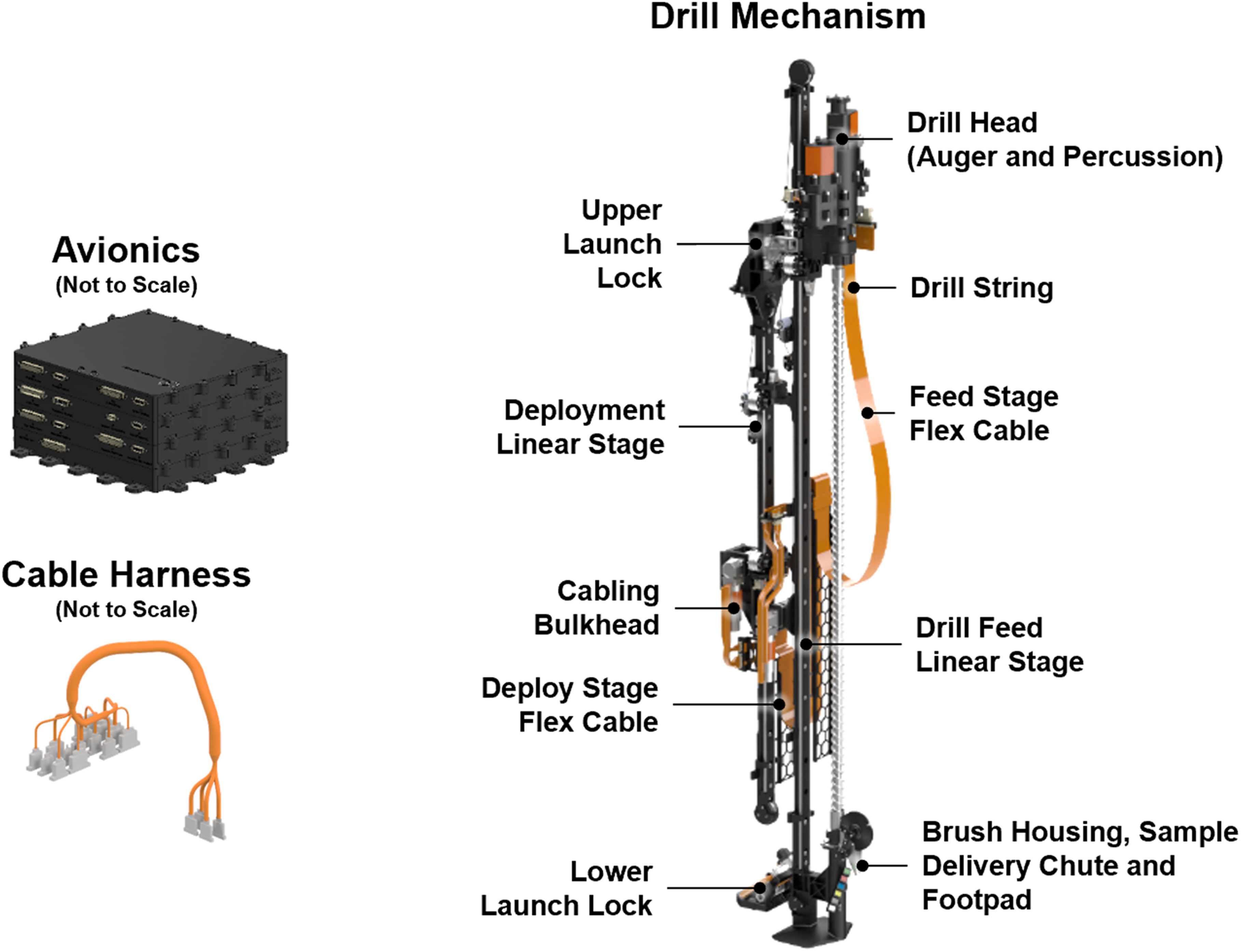 Source: [1], CC BY 4.0.
Overview
Section titled “Overview”A lunar polar volatiles mission has to answer a question orbital and impact data cannot: whether there is water at a specific spot, at what depth, and in what form, without melting or losing it in the act of finding out. Orbital neutron and reflectance data bound the problem to within a few weight percent and a few tens of centimeters of depth, and set the detection thresholds and lateral resolution a landed instrument needs to close the gap [3]. Closing it means putting a bit into permanently shadowed, cryogenic regolith and bringing the released volatiles to an instrument fast enough that sublimation has not already scattered them, which is a harder problem than excavating dry equatorial soil: the material may be indurated by ice cement rather than loose, cold enough to embrittle seals and gum lubricants, and valuable enough that the sample cannot simply be thrown away to get through it.
TRIDENT is the 1 m class rotary-percussive drill built by Honeybee Robotics to do this, on two lunar south pole missions: the PRIME-1 payload on the Intuitive Machines IM-2 Athena lander, and the VIPER rover [1], [14]. Two identical flight units were delivered, differing only in a set of calibration targets for VIPER’s near-infrared spectrometer. The drill does not analyze anything itself; its product is a cuttings cone deposited on the surface for a mass spectrometer, and on VIPER a spectrometer, to read, plus the telemetry the act of drilling generates [2].
Design space
Section titled “Design space”The design descends from two decades of Honeybee drills built to the same general problem on different bodies: the Construction and Resource Utilization eXplorer (CRUX) concept paired a borehole neutron probe and evolved-gas analyzer with a drill to map subsurface hydrogen directly rather than infer it from surface neutron counts alone [5]; Icebreaker and the Life in the Atacama drill worked the Mars case, where ice cemented ground had to be penetrated without melting the very ice being sought [4]; and Resource Prospector carried the lineage back to the Moon before its 2018 cancellation. Mass fell from over 50 kg at Icebreaker to 15 kg at the Life in the Atacama drill before rising again for the flight configuration, as the requirement moved from a rover-mounted demonstrator to a lander- and rover-qualified flight instrument [8].
Two choices distinguish TRIDENT from that lineage and from a conventional auger. Rotation and percussion are driven by separate actuators, so the drill can run in rotation alone, percussion alone, or both, and spend the percussor’s power only when the material needs it [1], [2]. Bench tests of commercial rotary hammers support the split: in 45 MPa limestone, in air at ambient temperature, rotary-percussive drilling reached about 1000 J/cc specific energy against about 5000 J/cc for rotary alone, and 130 cm/hr penetration against 9 cm/hr at 40 lbs weight on bit [22]. A piezoelectric percussive augmenter on an ordinary drill gained 1.5 to more than 10 times in drill rate in limestone by moving power from rotation to percussion at a fixed 160 W, and the gain fell in softer concrete when cuttings built up in the hole [23]. And the auger removes material in bites rather than boring one continuous hole: after about 10 cm of penetration it is withdrawn, a passive brush scrapes cuttings off, and a chute deposits them on the surface as a cone, before the drill re-enters the hole for the next 10 cm [8]. Bite sampling was chosen specifically to reduce the risk of freezing in on a re-entry into an empty hole, at the cost of an operation that pauses every 10 cm rather than running continuously [2]. Field testing shows what that choice buys and what it does not: at Haughton Crater and on the Bishop Tuff, TRIDENT penetrated unconsolidated and cuttings-permeable ground easily but choked and bound in low-permeability microporous targets, exceeding safety torque limits and requiring a wrench to free the auger, a fault the bite-sampling logic does not by itself prevent [7]. The operational fix demonstrated in the field was to cut the bite size from the nominal 10 cm down to 1 to 2 cm so cuttings are bailed more often, which restored slow, unassisted progress [7].
The site selection rests on laser altimetry of Shackleton crater, whose bright floor the authors attribute most simply to a lack of space weathering rather than to ice, with a roughly 20 percent surface ice layer offered only as an alternative [24]. TRIDENT flew on IM-2, launched 27 February 2025 and landed 6 March at Mons Mouton [14]. Athena came to rest on its side, so no hole was drilled; the drill was instead run through its full range of motion in a horizontal orientation while buried in regolith thrown up during landing. VIPER, delayed by cost and schedule growth documented in its own program reviews, had not flown as of this writing [6].
Other lunar drilling approaches
Section titled “Other lunar drilling approaches”Rotary-percussive bite sampling is one of several families, and the others differ in what they preserve. Core drills that bring a continuous sample to Earth are the only kind that has returned lunar material from depth: Apollo, Luna and Chang’e-5 sampled to depths of 25 to 305 cm, with returned masses from 55 g to 110.5 kg [15]. Chang’e-5 used a rotating outer pipe with helical blades and a static inner pipe lined with a soft sampling bag, aimed at about 2 m of core and recovered about 1 m, and separately scooped about 1.5 kg with a four-joint arm; the source gives no drill loads, power or reason for the shortfall [19]. A coring drill’s product is a sample for laboratory analysis, whereas TRIDENT’s is a cuttings cone read in place, so the two trade stratigraphic and volatile integrity against mass, power and the absence of a return vehicle. A proposed in-situ condition preserved coring concept would wrap the core in a self-healing polymer film to retain volatiles and bedding; the film has been measured only on a terrestrial bench at -20 C, and no integrated coring test has been reported [15].
Earlier Honeybee work on ice-bound lunar regolith used instrumented drill-press tests: a tungsten carbide and a polycrystalline diamond bit were run into frozen FJS-1 simulant at 10 wt% water and -85 C, and specific energy of drilling was correlated with independently measured compressive strength, from single runs per bit at ambient pressure [16]. That correlation is the antecedent of TRIDENT’s drill-telemetry strength estimate. Independent modeling work on lunar sampling augers finds that screw conveyance and chip extrusion, usually treated as dominant load terms, are three orders of magnitude too small to explain measured loads, that bulldozing dominates with cutting second, and that a penetration-to-rotary-speed ratio between 0 and 1 avoids jamming [17]. That result was obtained at 1 g and ambient conditions in one dry simulant, so it does not cover icy or cryogenic ground. A discrete element thermal model calibrated at -130 C (dry) and -120 C (5 percent ice) predicts a bit-region temperature rise of only 2 to 4 C on average and 6 to 8 C at most, and estimates negligible sublimation loss during drilling below about -100 C; the vacuum case is a model extrapolation and the experiments reached 100 mm depth [18].
Excavation is the other route to regolith access, and it trades depth for throughput. RASSOR 2.0 is a 66 kg vehicle with two opposed pairs of counter-rotating bucket drums, which cancel the horizontal reaction force so that digging does not depend on traction, and it carries an 80 kg regolith payload [20]. Its tilt-table wheel comparison used three attempts per configuration at one 25 degree angle in BP-1, and it saw no vacuum, thermal or dust testing, so its figures are design and prototype values [20]. The IPEx design that descends from it scales RASSOR 2 actuator loads by a 0.7 linear factor and reached TRL 5 through a four-test KSC qualification sequence at 1 g, one arm actuator surviving 1,402,223 input revolutions against a 337,000 revolution requirement [21]. Both are surface-layer excavators for bulk regolith, neither reaches the meter depths TRIDENT targets, and neither has flown.
Specifications
Section titled “Specifications”| Parameter | Value | Source |
|---|---|---|
| Total mass | 26.5 kg | [1] |
| Drill hardware mass | 19.5 kg | [8] |
| Avionics mass | 7 kg | [8] |
| Height | approximately 1.75 m | [1] |
| Bit diameter | 25.4 mm, percussive-grade carbide tip | [2] |
| Feed stroke | 1 m | [1], [2] |
| Deploy stage stroke | 0.35 m | [1] |
| Percussive blow energy | 2 J at up to 972 blows per minute | [2] |
| Percussor rated power | 300 W | [8] |
| Nominal rotary power | 50 W, 87 W average auger power | [1], [2] |
| Auger speed | 100 rpm nominal, 10 to 120 rpm commandable | [1] |
| Feed speed | 1.25 mm/s drilling, 2 mm/s otherwise, 0 to 4 mm/s commandable | [1] |
| Weight on bit | 100 N nominal, 0 to 500 N commandable | [1] |
| Linear stage rating | 500 N bidirectional | [2], [8] |
| Percussion rate | 729 blows per minute nominal, 0 to 1000 commandable | [1] |
| Bite length | 10 cm nominal, 1 to 10 cm commandable | [1], [8] |
| Cuttings per bite | about 12 cc per 10 cm | [8] |
| Actuators | four brushless DC, with planetary, spur and bevel gearing | [8] |
Mission profile
Section titled “Mission profile”| Parameter | Value | Source |
|---|---|---|
| Launch | 27 February 2025, 00:16:30 UTC | [1], [14] |
| Landing | 6 March 2025, about 17:30 UTC | [1], [14] |
| Landing site | Mons Mouton, 84.7906 S, 29.1957 E | [1], [14] |
| Lander attitude | on its side | [1] |
| Drill activation | about 20 minutes | [1] |
| Deploy stage extension achieved | 35 cm | [1] |
| Feed stage extension achieved | 100 cm | [1] |
| Regolith penetrated | none | [1] |
With the lander horizontal there was still enough power to exercise the drill. Over about twenty minutes both rotation and percussion actuators were run, both launch locks released, both linear stages driven to their full extension, the auger heater cycled, and the two drill string temperature sensors read out, all while the mechanism and avionics box were under a thick layer of regolith deposited during landing [1], [14]. The builders’ assessment is that the system operated within flight parameters and behaved as it had in preflight test.
VIPER’s assignment is different in kind: about three drilling deployments at each science station across a 100 Earth-day nominal mission in a 5 by 5 km area on Mons Mouton, with drill sites chosen tactically by the science team from the neutron spectrometer’s readings [1]. The lateral traverse VIPER adds is itself a response to how coarse orbital detection is: a rover that can range across a permanently shadowed region and stop wherever the subsurface neutron signal warrants is a different, and more capable, instrument than a single fixed drill [3].
Approach
Section titled “Approach”Two nested linear stages carry the drill. The deploy stage presses a footpad against the surface for stability, and the feed stage advances the string. Both use a steel wire rope capstan on a rolling carriage rather than a ball screw, chosen because lunar regolith is more abrasive than Martian dust and a ball screw fails if dust enters it [8]. The capstan also lets the drill head float during percussion, which is the mechanical analogue of not pushing down on a jackhammer.
The auger is built in two sections to serve the bite-sampling scheme. The lower sampling section has deep flutes so material jams in and stays there; the longer upper section has shallow flutes for conveyance [8]. The combination is deliberately efficient at sampling and inefficient at conveying, so drilling a full meter in one run raises torque and power and increases the chance of a cuttings jam. Three consequences follow from bite sampling itself [8]: the cuttings retain a 10 cm stratigraphy instead of being mixed over a meter; drilling torque stays low, because cuttings are never conveyed the full height of the hole, and on re-entry to an empty hole the initial torque can be attributed to material strength alone rather than to strength plus chip transport; and the bit has time to cool between bites, which matters for retaining volatiles in the sample.
Mobility
Section titled “Mobility”None. TRIDENT is fixed to its host and reaches only along its own feed axis.
Power and energy
Section titled “Power and energy”Nominal rotary drilling power is 50 W to 87 W average; the percussor is rated at 300 W [1], [2], [8]. No battery is carried and no energy budget for a complete hole is published. On PRIME-1 the entire activation ran on power the toppled lander could still supply.
Thermal
Section titled “Thermal”Kapton film heaters warm the avionics and actuators to operating temperature, and a heater inside the auger with a colocated temperature sensor 35 cm above the bit serves three purposes: thermal conductivity measurement, freeing the string if ice adheres to it, and driving sublimation from the cuttings pile [9]. Flight units passed thermal vacuum, vibration, shock and electromagnetic compatibility testing. Bit temperature during drilling is itself a measurement rather than a constraint: in engineering unit tests the bit cooled at visibly different rates in dry and in icy simulant, because dry lunar soil is insulating and the stem retains more heat in it [1].
Compute and avionics
Section titled “Compute and avionics”The avionics box holds four motor drivers, a thermal card, a power distribution unit and a command and data handling board [9]. Onboard software commutates the brushless motors and strings low-level actuator commands into named operations: release launch locks, calibrate actuators, deploy the footpad, drill, retract to deposit cuttings, stow. No processor part or radiation tolerance approach is published. A rotary slip ring carries power and data to the auger heater and its two platinum resistance thermometers, and flex harnesses carry power and data across the full travel of both stages.
Autonomy
Section titled “Autonomy”The drill is operated in near real time rather than autonomously, a decision the builders justify as simplifying avionics development while letting operators catch slippage, clogging and unanticipated behavior as it happens [2]. One behavior is onboard: percussion is normally triggered automatically when feedback shows the drill is making insufficient progress. Everything else is commanded.
Communications
Section titled “Communications”Through the host vehicle. No band, rate or latency figure is published for the drill itself.
Payload and instruments
Section titled “Payload and instruments”TRIDENT carries two platinum resistance temperature detectors, one integrated in the drill bit and one in the auger beside the heater, and no other instrument [8]. Its scientific output is otherwise indirect: the cuttings cone it builds is what MSolo and, on VIPER, NIRVSS measure, and its own telemetry is a geotechnical instrument. MSolo is itself a modified commercial residual gas analyzer, ruggedized for flight and qualified through vibration, thermal vacuum and EMI/EMC testing before delivery, with its ground-measured limit of detection and isotope-ratio reproducibility deferred to lunar performance that has not yet been measured [10].
Three derived measurements come out of drill telemetry. Specific drilling energy relates to unconfined compressive strength through an empirical baseline fitted across rocks from 4 to 120 MPa, and rate of penetration varies inversely with the same quantity [1]. Cone index follows from weight on bit and penetration rate before drilling starts. A modified footpad deployment, driven under current limiting with position telemetry read back, yields a force-penetration curve and from it the modulus of subgrade reaction and ultimate bearing capacity, quantities used in the Apollo era to predict how far surface packages would sink [11]. Those Apollo-era relations were built from six equatorial sites and carry their own stated caveat that a footing loaded outside the stress range they were fitted in is being extrapolated [11], a caveat that applies directly to a polar footpad reading taken at loads and temperatures Apollo never measured. A more recent synthesis of the same Apollo and Soviet dataset gives closed-form density and shear-strength-with-depth curves an excavator or driller can size against, while noting that almost none of the underlying data is from polar terrain [12].
A thermal vacuum campaign with the engineering unit and a flight MSolo unit drilled four 1 m holes into a 100 kg bin of lunar highlands simulant doped to 0, 2.5 and 5 weight percent water, at 1.6e-6 Torr and about -178 C, and showed that a mass spectrometer watching the cuttings pile can distinguish the doping levels by the water signal, with peak intensity correlating to a water fluence computed from the pile’s own geometry [9]. Pile dynamics, cuttings falling back into the hole or spilling past the bin edge, produced large spurious spikes and complicated that reading, and only one of the four holes had its pile geometry measured directly, so the fluence correlation is fitted to a single hole [9].
A separate Antarctic field campaign with the engineering unit showed that drill telemetry alone identifies subsurface horizons: an ice-rock transition at about 62 cm, a frozen boundary at 20 cm, and a bubble-rich ice layer at about 50 cm that matched published bubble content peaks [8]. Ice, soft soil and hard rock each produce a distinct signature in torque, weight on bit and penetration rate. Those results come from Antarctic ice and till at Earth gravity, not lunar regolith, and the fault detector built on them was tuned on the same data it was later scored against rather than validated blind [8].
The percussor has also been examined as a seismic source. A single 2 J blow produces an impulse above 50 Hz detectable 62 to 76 dB above the noise floor on accelerometers mounted on the drill chassis [9]. The flight inertial measurement units on both missions sample at 100 Hz against the 200 Hz used in the laboratory, so content above 50 Hz may not survive.
Ground testing
Section titled “Ground testing”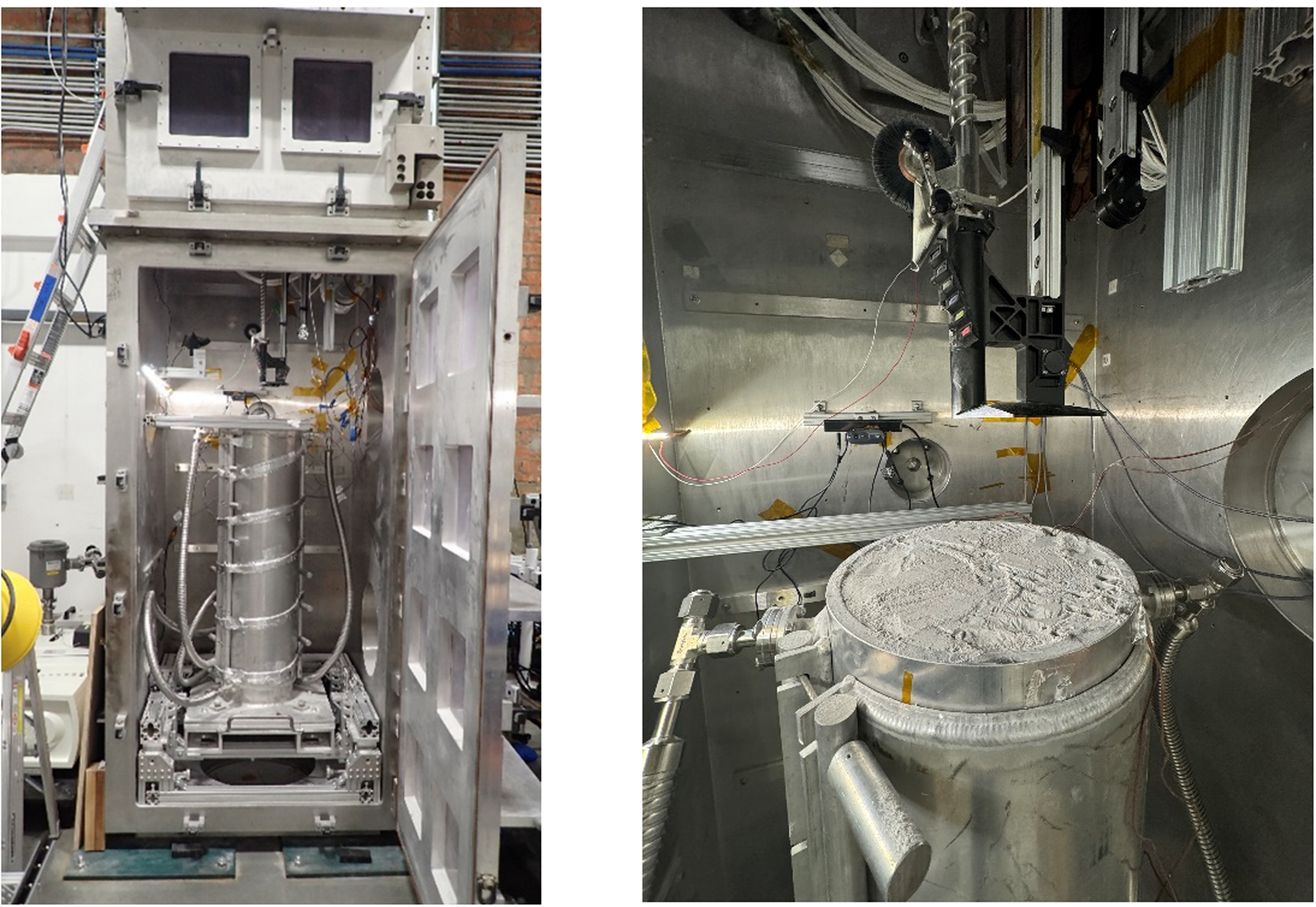 Source: [1], CC BY 4.0.
Flight units were environmentally tested but never used to drill simulant, and their drill strings were replaced after testing, so no flight-unit drilling data exists [1], [7]. All vacuum drilling performance comes from a dedicated engineering unit, which cut nearly 30 m in roughly 1 m intervals across 337 bites and more than 30 hours.
| Test condition | Result | Source |
|---|---|---|
| NU-LHT-2M and LSP-2 simulants, below -100 C and below 1e-4 Torr | no measurable dust ingress effect on actuator no-load currents | [1] |
| LSP-2 doped to 8.5 wt% water, vacuum | bit cooling rate distinguishes icy from dry soil | [1] |
| NU-LHT-3M doped 0, 2.5, 5 wt% water, 1.6e-6 Torr, -178 C, with flight MSolo | mass spectrometer distinguishes doping levels; pile geometry confounds later holes | [9] |
| Rock coupons, 4 to 120 MPa unconfined compressive strength | specific drilling energy and penetration rate baselines | [1] |
| Percussive drilling to failure | cam-spring life 2 to 3 days of continual percussion | [8] |
| Haughton Crater and Bishop Tuff field campaigns | choked and bound in low-permeability targets; bite size reduction restored progress | [7] |
| Antarctic field campaign, 15 boreholes | percussive head broke after two days, repaired from field spares | [8] |
Simulant choice itself bounds what these results transfer: the NASA simulant workshop report argues from Apollo hardware failures that surface systems need testing against traceable standard materials, and records that the earlier JSC-1 and MLS-1 simulants were poorly characterized and never quality controlled as reference materials [25]. The icy simulants are not lunar ice. Qualitative volatile measurement was not a baselined requirement on either mission, so no complex ice-formation method was used and the samples are water-doped simulant rather than an analogue of the polar deposits the drill was built to sample [9]. Reduced-gravity strength testing of terrestrial sand, run on parabolic flight with only two to three data points at lunar gravity, finds that residual friction angle and dilatancy shift with gravity in ways a 1 g or vacuum-chamber-at-1 g drilling test cannot reproduce, which bears on how far any of the ground campaigns above stand in for lunar surface conditions even where vacuum and temperature are matched [13].
Modes of operation
Section titled “Modes of operation”Rotation, percussion, and rotation with percussion, selected by the operator or triggered onboard when progress stalls [2]. Between these sit the named sequences the flight software carries: launch lock release, actuator calibration, footpad deployment, drilling, retraction with brushing, and stow.
Ground operations
Section titled “Ground operations”Three console roles: a payload uplink lead who owns execution and sends every command, a payload downlink lead who watches telemetry and reports instrument health, and a TRIDENT Science role that represents the drill in the science center, recommends drill sites and advises when conditions warrant deviating from the procedure [1]. On VIPER the uplink and downlink leads sit in the payload operations control center and the science role in the mission science center; on PRIME-1, with fewer instruments and a slower pace, all three were colocated with MSolo. The ground software is a graphical interface named Poseidon that sets command parameters, sends commands, and displays telemetry as indicators, plots and event records; procedures are organized in a separate tool named PRIDE so that drilling can be synchronized with the instruments watching the cuttings pile. VIPER’s own ground test program before the 2022 program review exercised rover-side systems around the drill, not the drill itself: a 40 km wheel endurance run, slip characterization, and sink-tank tests in fine glass beads to develop escape gaits should the rover become entrapped near a science station [6].
Technologies developed
Section titled “Technologies developed”The bite-sampling architecture, and the pairing of a deep-fluted sampling auger with a shallow-fluted conveying auger that makes it work, is the transferable result, refined against the specific failure mode, ice-cemented and microporous ground choking a continuous auger, that stopped its Mars-drill predecessors [4], [7]. So is the capstan and rolling carriage feed, adopted specifically because a ball screw is vulnerable to abrasive dust, and the decoupling of rotation from percussion so that percussive power is spent only when the material demands it.
The empirical relations between drill telemetry and material properties are the second result, and they are what makes a drill a geotechnical instrument rather than only a sample acquisition device: specific drilling energy against compressive strength, rate of penetration against the same, bit cooling rate as a qualitative indicator of ice, and footpad force-penetration as a bearing capacity measurement [1]. The Antarctic campaign extended these into automated horizon detection from telemetry alone [8].
What is not established
Section titled “What is not established”Every penetration number attributed to TRIDENT is from a ground engineering unit in simulant or terrestrial rock, or from terrestrial field sites at Haughton Crater, Bishop Tuff and in Antarctica, not from lunar regolith [1], [7], [8]. PRIME-1’s flight activation exercised mechanisms while buried in regolith thrown up at landing, without drilling a hole, and VIPER has not flown. The icy simulants used in every vacuum test are water-doped analogs prepared without a complex ice-formation method, since qualitative volatile measurement was not a baselined requirement, and are not an analogue of the polar deposits the drill was built to sample [9]. The mass-spectrometer thermal vacuum campaign that comes closest to true polar conditions measured pile geometry, the quantity its water signal is calibrated against, on only one of its four holes [9]. The bearing capacity and shear strength relations used to interpret footpad telemetry, both the original Apollo-era values and the more recent synthesis of them, are built almost entirely from equatorial and mid-latitude sites and are explicitly not qualified for polar regolith [11], [12], and separate reduced-gravity testing shows soil strength parameters shift with gravity level in ways no drilling test at Earth gravity captures [13]. The Antarctic telemetry-based fault detector was tuned on the same campaign it was scored against rather than validated on independent data [8]. The thermal result that sublimation loss during drilling is negligible rests on a model extrapolated to vacuum from atmospheric-pressure experiments to 100 mm depth, and the auger load model that identifies bulldozing as dominant was fitted in one dry simulant at 1 g, so neither has been checked against a TRIDENT-class bit in icy ground in vacuum [17], [18]. No flight drilling result exists for TRIDENT on either mission as of this writing.
References
- Zacny, K., Chu, P., Vendiola, V., Paulsen, G., Creekmore, J., Goldman, J., Kleinhenz, J., Smith, J. and Colaprete, A. (2025). TRIDENT Ice Mining Drill for Lunar Volatile Prospecting for PRIME-1 and VIPER Missions
. The Planetary Science Journal, 12. Source
BibTeX
@article{zacny2025trident, title = {{TRIDENT} Ice Mining Drill for Lunar Volatile Prospecting for {PRIME-1} and {VIPER} Missions}, author = {Zacny, Kris and Chu, Philip and Vendiola, Vincent and Paulsen, Gale and Creekmore, Justin and Goldman, Jason and Kleinhenz, Julie and Smith, James and Colaprete, Anthony}, journal = {The Planetary Science Journal}, volume = {6}, number = {12}, pages = {297}, year = {2025}, doi = {10.3847/psj/ae0b51}, abstract = {Abstract The Regolith and Ice Drill for Exploration of New Terrains (TRIDENT) is a 1 m class drill developed for capturing regolith and ice during the Volatiles Investigating Polar Exploration Rover (VIPER) and the Polar Resources Ice Mining Experiment (PRIME-1) lander missions to the south pole of the Moon. The drill employs decoupled rotation and percussion mechanisms to allow for three modes: rotation, percussion, and rotation–percussion, depending on operational goals and the material strength. TRIDENT can be operated in such a way that it can characterize subsurface material and deliver cuttings to the surface for characterization by other instruments. TRIDENT includes a drill-bit-integrated temperature sensor and an auger-integrated heater with a colocated temperature sensor 35 cm above the bit for thermal conductivity measurement. The heater can also be used in cases of ice adherence (freezing in) and to enhance the sublimation of ice from the cuttings pile. TRIDENT collects and delivers subsurface regolith onto the surface using a “bite” sampling approach: cuttings are captured in the auger flutes, the auger is retracted after drilling a 10 cm bite, and then 10 cm worth of cuttings are deposited onto the surface, forming a cuttings cone. This regolith cone is then analyzed by instruments Mass Spectrometer Observing Lunar Operations (MSOLO) and NIRVSS on the VIPER and MSOLO on the PRIME-1 missions. The drilling activity creates a seismic signal that can be detected on any associated inertial measurement unit that is turned on during the activity, which enables seismic science. TRIDENT represents two decades of technology development for planetary applications and could be deployed on any future missions to other solar system bodies. TRIDENT on the PRIME-1 mission has been successfully deployed in horizontal orientation (this orientation was due to the lander being in an off nominal landing orientation). All actuators, sensors, and heaters worked as designed. Even though the drill did not penetrate regolith, it was covered in regolith that fell onto the drill during the landing operation. VIPER is scheduled to launch to the Moon at the end of 2027 on Blue Origin’s Mk1 lander.} } - Quinn, J., Captain, J., Eichenbaum, A., Aguilar-Ayala, R., Kleinhenz, J. E., Zacny, K. A., Chu, P. and Vendiola, V. (2023). Polar Resources Ice Mining Experiment-1 (PRIME-1) NASA’s First Polar Drilling and Volatiles Detection Mission, 20230007582. ntrs.nasa.gov/citations/20230007582
BibTeX
@misc{quinn2023polar, title = {Polar Resources Ice Mining Experiment-1 (PRIME-1) NASA’s First Polar Drilling and Volatiles Detection Mission}, author = {Quinn, J.W. and Captain, J.E. and Eichenbaum, A.S. and Aguilar-Ayala, R. and Kleinhenz, Julie E. and Zacny, Kris A. and Chu, P.C. and Vendiola, V.R.}, howpublished = {Presentation at the Kennedy Space Center}, number = {20230007582}, year = {2023}, url = {https://ntrs.nasa.gov/citations/20230007582}, abstract = {The US Administration announced in 2019 that NASA would return to the Moon where it would seek to establish a sustainable lunar presence. In Situ Resource Utilization (ISRU) is needed to sustain and grow hu-man surface exploration and it is therefore a vital part of ensuring this bold endeavor. ISRU requires ground-truth on physical, mineral, and volatile characteristics of the resources. Water, a key and game-changing resource, exists in the polar regions of the Moon. Learning to harvest and use this resource first requires understanding where the resource is abundantly located and on what scales. Harvested water, which is usable for life support and fuel, must be identified, quantified, and assessed for its mining feasibility. The project goal for PRIME-1 is to develop a flight-ready instrumentation package that can assess the volatiles at a polar lunar landing location. PRIME-1 is the combination of two instruments; Mass Spectrometer observing lunar operations (MSolo) and The Regolith and Ice Drill for Exploring New Terrain (TRIDENT). TRIDENT is an 1-meter augering drill capable of bringing incremental lunar regolith samples to the surface for volatile analysis. MSolo is a modified, commercial-off-the-shelf (COTS) mass spectrometer capable of qualifying and quantifying atomic species in the 1-100 amu range, including isotopic differentiation. These two lunar flight instruments operating together make up the PRIME-1 instrument suite. PRIME-1 intends to fly on and operate from a static lunar lander acquired by the NASA Commercial Lunar Payload Services (CLPS) acquisition process. The PRIME-1 payload suite was selected to fly on Intuitive Machines Nova-C lander, and is currently targeting a late Fall 2023 landing attempt. } } - Kleinhenz, J., McAdam, A., Colaprete, A., Beaty, D., Cohen, B., Clark, P., Gruener, J., Schuler, J. and Young, K. (2020). Lunar Water ISRU Measurement Study (LWIMS): Establishing a Measurement Plan for Identification and Characterization of a Water Reserve
. NASA, NASA/TM-20205008626. Source
BibTeX
@techreport{kleinhenz2020lunar, title = {Lunar Water {ISRU} Measurement Study ({LWIMS}): Establishing a Measurement Plan for Identification and Characterization of a Water Reserve}, author = {Kleinhenz, Julie and McAdam, Amy and Colaprete, Anthony and Beaty, David and Cohen, Barbara and Clark, Pamela and Gruener, John and Schuler, Jason and Young, Kelsey}, number = {NASA/TM-20205008626}, institution = {NASA}, year = {2020}, url = {https://www.lpi.usra.edu/lunar/strategies/KleinhenzEtAl_NASA-TM-20205008626_ISRU%20MeasurementStudy.pdf} } - Glass, B., Bergman, D., Yaggi, B., Dave, A. I. and Zacny, K. (2016). Icebreaker-3 Drill Integration and Testing at Two Mars-Analog Sites
. Ames Research Center, 20160006480. Source
BibTeX
@techreport{glass2016icebreaker, title = {Icebreaker-3 Drill Integration and Testing at Two Mars-Analog Sites}, author = {Glass, B. and Bergman, Dean and Yaggi, B. and Dave, Arwen I. and Zacny, K.}, number = {20160006480}, pages = {472-482}, institution = {Ames Research Center}, year = {2016}, doi = {10.1061/9780784479971.045}, abstract = {A decade of evolutionary development of integrated automated drilling and sample handling at analog sites and in test chambers has made it possible to go 1 meter through hard rocks and ice layers on Mars. The latest Icebreaker-3 drill has been field tested in 2014 at the Haughton Crater Marsanalog site in the Arctic and in 2015 with a Mars lander mockup in Rio Tinto, Spain, (with sample transfer arm and with a prototype life-detection instrument). Tests in Rio Tinto in 2015 successfully demonstrated that the drill sample (cuttings) was handed-off from the drill to the sample transfer arm and thence to the on-deck instrument inlet where it was taken in and analyzed ("dirt-to-data").} } - Haldemann, A. F. C., Johnson, J. B., Elphic, R. C., Boynton, W. V. and Wetzel, J. (2006). Construction and Resource Utilization Explorer (CRUX): implementing instrument suite data fusion to characterize regolith hydrogen resources
. IEEE Aerospace Conference. Source
BibTeX
@inproceedings{haldemann2006construction, title = {Construction and Resource Utilization Explorer (CRUX): implementing instrument suite data fusion to characterize regolith hydrogen resources}, author = {Haldemann, Albert F. C. and Johnson, Jerome B. and Elphic, Richard C. and Boynton, William V. and Wetzel, John}, booktitle = {IEEE Aerospace Conference}, pages = {1-10}, year = {2006}, doi = {10.1109/aero.2006.1655738}, abstract = {CRUX is a modular suite of geophysical and borehole instruments combined with display and decision support system (Mapper/DSS) tools to characterize regolith resources, surface conditions, and geotechnical properties. CRUX is a NASA-funded Technology Maturation Program effort to provide enabling technology for lunar and planetary surface operations (LPSO) (Johnson et al., 2005). The Mapper/DSS uses data fusion methods with CRUX instruments, and other available data and models, to provide regolith properties information needed for LPSO that cannot be determined otherwise. We demonstrate the data fusion method by showing how it might be applied to characterize the distribution and form of hydrogen using a selection of CRUX instruments: borehole neutron probe and thermal evolved gas analyzer data as a function of depth help interpret surface neutron probe data to generate 3D information. Secondary information from other instruments along with physical models improves the hydrogen distribution characterization, enabling information products for operational decision-making.} } - Andrews, D. (2023). VIPER: Systems Integration Status
. International Astronautical Congress, 20230001799. Source
BibTeX
@inproceedings{andrews2023viper, title = {VIPER: Systems Integration Status}, author = {Andrews, Daniel}, booktitle = {International Astronautical Congress}, number = {20230001799}, institution = {NASA}, address = {Baku}, year = {2023}, url = {https://ntrs.nasa.gov/citations/20230001799}, abstract = {NASA’s Artemis Program plans to return humans to the Moon for an extended stay. To do so will require substantial resources to sustain that continued human presence, including continuous supplies delivered from the Earth. Given the expense and complexity of resource deliveries from Earth, if some resources were indigenously available, substantial logistical savings could be available by “living off the land”, wherever possible. The LCROSS[1] , LRO and other missions have confirmed the presence of resources such as water-ice and other volatiles in lunar polar regions, so the next step is to understand the scientific nature and physical distribution of those candidate resources. Those local volatiles could be processed into propellants and human life-supporting needs, reducing risk of maintaining a permanent human presence on the Moon. The Volatiles Investigating Polar Exploration Resource (VIPER) is a surface mobility scientific platform, designed to spend ~100 days mapping and surveying four different Ice Stability Regions to understand the scientific nature and distribution of water and other volatiles. VIPER will also provide scientific mineralogical context of the lunar regolith, such as the presence of silicon and light metals in lunar regolith, providing a composite picture of resource availability and sustainment. This paper will discuss the latest systems-level integration activities by the VIPER team, following our initial introduction to this mission at IAC2021[2] . The VIPER team successfully passed its Systems Integration Review (SIR) in late-2022, and in early 2023, began system-level surface segment (rover) flight hardware assembly. VIPER is managed within NASA’s Science Mission Directorate (SMD), utilizing the Commercial Lunar Payload Services (CLPS) lunar delivery model with partner, Astrobotic, Inc.} } - Glass, B., Stoker, C., Battah, H., Boelter, S., Fortuin, C., King, I., Stevenson, T. and Stucky, T. (2024). TRIDENT Drill Validation at Mars and Lunar Analog Field Sites
. Lunar and Planetary Science Conference. Source
BibTeX
@inproceedings{glass2024trident, title = {{TRIDENT} Drill Validation at Mars and Lunar Analog Field Sites}, author = {Glass, Brian and Stoker, Carol and Battah, Hussein and Boelter, S. and Fortuin, C. and King, I. and Stevenson, T. and Stucky, T.}, booktitle = {Lunar and Planetary Science Conference}, year = {2024}, url = {https://ntrs.nasa.gov/citations/20240000585}, abstract = {Drilling on Earth is typically a human-intensive activity. Drilling on other planets is further complicated by the lack of prior local field surveys of their target area, hence blindly drilling into uncertain target rocks. Field conditions on the Moon or Mars are also different than for shallow drilling on Earth: lower temperatures and pressures, less power available, low masses (hence less weight-on-bit). Given the cost of transport from Earth, no drilling muds or working fluids are likely to be available to carry away cuttings. And impact-gardened regolith and dust vary mechanically and texturally from most terrestrial soils. The Regolith and Ice Drill for Exploration of New Terrains (TRIDENT) is a rotary-percussive 1m-class drill from Honeybee Robotics. It is low-power (rotary and percussive actuators are 200 W each) and lightweight (<20 kg) with the maximum weight on bit limited to 200 N. TRIDENT has been manifested for the Volatiles Investigating Polar Exploration Rover (VIPER) and PRIME-1 lunar south pole missions in 2024, has previously been field tested at a hot, dry analog site in the Atacama Desert, and in lunar conditions in thermal vacuum chamber tests. TRIDENT was also part of the 2019 Icebreaker Mars Discovery proposal, as well as in the Mars Life Explorer concept. During ARADS tests, drill control and fault recovery automation software enabled hands-off operations of a rover-mounted TRIDENT drill. TRIDENT Drill Analog Site Validation: Past TRIDENT tests in thermal vacuum (TVAC) chambers targeted containers of manufactured lunar simulants with added volatiles. 2022 TRIDENT ambient testing at NASA Ames drilled into cemented lunar simulant materials. Low cuttings-permeability led to cuttings buildup, and drill choking and binding was observed. The Atacama analog site in ARADS had desiccated unconsolidated sediments that did not challenge the TRIDENT design. However, lunar polar regolith is expected to be diverse and heterogeneous with varying clast sizes, with abundant impactites and perhaps subsurface ice deposits. Neither the simulants nor Atacama testing had completely covered the TRIDENT-targeted field characteristics, motivating further analog tests prior to the planned lunar missions. To gain more insight into the behavior of the TRIDENT hardware in diverse impactites and subsurface ice, and to verify the software automation in that environment, in August 2023 TRIDENT was brought to Haughton Crater, a field analog site in the Canadian Arctic. In September 2023 the same drill was brought to the Bishop Tuff in southern California to verify whether drilling binding behaviors previously seen in lunar simulant testing would be observed in naturally occurring fine-grained massive layers. The ~22 Ma Haughton Crater impact structure is located at 75 ̊22’ N, 89 ̊41’ W, on northwestern Devon Island, Nunavut, Canada. Numerous deposits of pale-grey crater-fill polymictic impact-melt breccia are found within the crater with a typical thickness reaching ~125 m or greater and covering ~60 km<sup>-2</sup>. An approximately 600m-thick permafrost layer is also present with ice typically found within 0.5-0.6m of the surface. The volcanic tableland north of Bishop, CA exposes densely welded tuff laid down during the eruption that created the Long Valley Caldera at approximately 0.76 Ma. Extensional faults and the Owens River gorge expose cross-sections across the plateau. The area is viewed as an analog site for Mars features believed to be of pyroclastic origin. Results: Haughton Crater.Drilling tests were conducted 8-13 August 2023 at a previously undisturbed area separated 5-10 m from past years’ Drill Hill test sites (75.4208, -089.7613). In six days, TRIDENT drilled 8 holes to nearly 1 m depth each, totaling 7.80 m. The active layer/ice boundary was at ~67 cm depth, with a total of approximately 2.4 m drilled into ice or ice-cemented impact breccia. During drilling, five drill fault states were observed and successfully recovered. Holes 23-1, 4 and 7 were drilled under manual control, using Honeybee’s Thorax user interface. Holes 23-5, 6, and 8 were drilled with the Ames IBexec automated drilling control software. TRIDENT was observed to have little difficulty in the thawed uncemented impact breccia above the active layer boundary, but required percussion to make slower headway in the ice-cemented breccia. In Hole 23-7 (Fig.1), drilling slowed down in a massive unit just above the active-layer boundary (perhaps a large rock extending into the ice-cementation?), with only 7cm progress made in 27 minutes of high auger torque and constant percussion, leading to a choking fault and then a binding fault. A similar pattern had been observed in TRIDENT Rio Tinto test data from 2017 [6] as well as in the 2022laboratory tests.Bishop Tuff.A team from NASA Ames and the US Geological Survey deployed the same TRIDENT drill to Bishop Sites 1B and 1C (37.4203, -118.4289; 37.4265, -118.4215) on 13-16 September 2023, on the Bishop Tuff plateau. A third drill site was used 17-18 September 2023(37.4598, -118.3667) in an abandoned pumice mine. Four holes (totaling 2.5m depth) were drilled into the fine-grained, meters-thick tuff units at Sites 1B and 1C, and a further two boreholes (totaling 1.98m depth) were made at the pumice site. Drill behavior in the tuff below 10 cm depth was similar to that seen at 65-74 cm depth in Haughton Hole 23-7 (Fig. 1) and that seen in the 2022 lab simulant drilling. Drill safety torque limits were exceeded multiple times resulting in drill stops downhole. These freezes then required external added torques (with a pipe wrench) to resume rotation, to unstick the drill for withdrawal. To prevent this choking and binding behavior we found that more-frequent cuttings removal was necessary, e.g., reducing the “drill bite” size from the nominal 10 cm to 2 cm per bite --bringing the auger up to the surface more frequently, as seen in Bishop Site 1C Hole 2 (Fig.2). This permitted slow progress without drill binding and without external interventions. Conversely, TRIDENT drilling in the more porous pumice target material showed no cuttings buildup issue, and single bites as large as 40 cm were demonstrated. Discussion: We observed that TRIDENT easily penetrated unconsolidated heterogeneous soils (both above the active layer boundary at Haughton and previously in the Atacama). Cemented or consolidated targets that were cuttings-permeable (icy impact breccia, pumice) required more energy applied and percussion. However, in non-cuttings-permeable targets (welded microporous tuff, cemented simulants, boulder) TRIDENT was observed to be prone to excessive cuttings accumulation leading to choking/binding faults and stalling. The wedge cutting bit, used by TRIDENT in field tests and in its flight versions, pulverizes the target rock and creates fine cuttings that ideally are transported up the auger spirals for removal. In porous, fractured or vesicular target materials (such as at the Bishop pumice site) a significant portion of the cuttings are pushed aside, but for non-fractured, microporous targets the cuttings remain in the borehole and accumulate. Rock powder is relatively incompressible as a working fluid at only 100-200N downward force (TRIDENT limits) and hence eventual drilling progress slows or stops. Our recommended strategy for improving TRIDENT cuttings removal in massive target units with low cuttings-permeability is to reduce TRIDENT bite sizes when encountering these units, from 10cm to as little as 1-2cm, to effectively bail the accumulating cuttings. This approach was demonstrated to reduce choking and allowed slow progress to continue in cuttings-impermeable microporous target units (viz. the Bishop tuff in our September 2023 tests or cemented simulants in 2022 ambient tests). } } - Boelter, S., Brown, G., Stucky, T., Temesgen, E., Mai, R., Weber, L., Gini, M., Bergman, D., Fortuin, C., Glass, B. and Wilhelm, M. (2026). TRIDENT Drill Performance and Subsurface Fault and Anomaly Detection in Antarctic Environments
. Annals of Glaciology. Source
BibTeX
@article{boelter2026trident, title = {TRIDENT Drill Performance and Subsurface Fault and Anomaly Detection in Antarctic Environments}, author = {Boelter, Sarah and Brown, Greta and Stucky, Thomas and Temesgen, Ebasa and Mai, Rene and Weber, Lucas and Gini, Maria and Bergman, Dean and Fortuin, Carter and Glass, Brian and Wilhelm, Marybeth}, journal = {Annals of Glaciology}, year = {2026}, url = {https://ntrs.nasa.gov/citations/20260007172}, abstract = {The Regolith and Ice Drill for Exploring New Terrain (TRIDENT), a 1-meter rotary percussive drill developed by Honeybee Robotics, is designed for extraterrestrial subsurface exploration. Because extraterrestrial drilling cannot rely on prior subsurface characterization or direct human operation, adaptive state estimation and anomaly detection are necessary for reliable autonomous drilling. We evaluate TRIDENT’s drilling performance in planetary analog environments during fieldwork in Schirmacher Oasis and Lake Untersee, Antarctica, including cold-desert permafrost terrain, glacially smoothed rock, ice-covered surfaces, subsurface frozen boundary layers, and ice-rock transitions representative of planetary subsurfaces. This paper investigates subsurface fault and anomaly detection methods for planetary drilling with minimal prior training data while further characterizing TRIDENT’s operational performance across representative analog terrains.} } - Ayala, R. A., Crabtree, M. A., Hancock, M. L., Jarnot, A., Captain, J. E., Kleinhenz, J., Rezich, E., Zacny, K., Vendiola, V., Mank, Z., Wright, K. C., Winfield, J. L., Orlando, T., Jones, B., Metzger, P. and Quinn, J. W. (2025). Mass Spectrometry Monitoring of Drilling Operations in Water-Doped Lunar Simulant under Cryogenic Conditions
. Advances in Space Research, 20250007225. Source
BibTeX
@techreport{ayala2025mass, title = {Mass Spectrometry Monitoring of Drilling Operations in Water-Doped Lunar Simulant under Cryogenic Conditions}, author = {Ayala, Roberto Aguilar and Crabtree, Morgan A and Hancock, Matthew L and Jarnot, Alexander and Captain, Janine E and Kleinhenz, Julie and Rezich, Erin and Zacny, Kris and Vendiola, Vincent and Mank, Zack and Wright, Kenneth C and Winfield, Jamie L and Orlando, Thomas and Jones, Brant and Metzger, Philip and Quinn, Jacqueline W}, volume = {77}, number = {20250007225}, pages = {7982-7994}, institution = {Advances in Space Research}, year = {2025}, doi = {10.1016/j.asr.2026.02.047}, abstract = {The utilization of analytical instruments for the detection and quantification of volatiles on the Moon is crucial for the development of in situ resource utilization technology. A test campaign under cryogenic conditions aimed to simulate the cold lunar environment of permanently shadowed regions (PSRs). The test campaign was performed in a Thermal Vacuum Chamber (TVAC) equipped with a bin of regolith simulant doped at three increasing water concentrations delineated at specific depths (Dry, 2.5, and 5 wt%, respectively). The average operating pressure of the chamber was 1.6×10 -6 Torr with an average regolith temperature of -178°C. Four holes were drilled into the regolith simulant bin using The Regolith and Ice Drill for Exploring New Terrain (TRIDENT) drill. The resulting cuttings-piles and their volatile activity were monitored via the Mass Spectrometer observing lunar operations (MSolo) instrument to determine the extent to which a mass spectrometer can monitor the release of volatiles during drilling activities in lunar-like environments. The results of this campaign helped to plan for the operation and subsequent data interpretation of the Polar Resources Ice Mining Experiment-1 (PRIME-1) mission on the Moon.} } - Aguilar Ayala, R., Captain, J. E., Smith, J. T., Hancock, M. L., Jarnot, A. W., Smith, K. E., Johnson, P. J., Johnson, C. S., Carro, R., Nieves, R. J., Bond, C. N., Trautwein, J., Wright, K. C., Winfield, J. L., Santariello, P., McAdam, A., Archer, P. D., Kreinheder, G., Diaz, J. A., Prem, P., Mandt, K. E., Gawronska, A., Cohen, B. A. and Quinn, J. W. (2025). VIPER's Mass Spectrometer Observing Lunar Operations (MSolo)
. The Planetary Science Journal, 11. Source
BibTeX
@article{aguilar2025vipers, title = {{VIPER}'s Mass Spectrometer Observing Lunar Operations ({MSolo})}, author = {Aguilar Ayala, Roberto and Captain, Janine E. and Smith, James T. and Hancock, Matthew L. and Jarnot, Alexander W. and Smith, Kevin E. and Johnson, Prital J. and Johnson, Christopher S. and Carro, Rodolphe and Nieves, Rolando J. and Bond, Christopher N. and Trautwein, John and Wright, Kenneth C. and Winfield, Jaime L. and Santariello, Peter and McAdam, Amy and Archer, P. Douglas and Kreinheder, Gregory and Diaz, Jorge A. and Prem, Parvathy and Mandt, Kathleen E. and Gawronska, Aleksandra and Cohen, Barbara A. and Quinn, Jaqueline W.}, journal = {The Planetary Science Journal}, volume = {6}, number = {11}, pages = {277}, year = {2025}, doi = {10.3847/psj/ae0a4e}, abstract = {Abstract The Volatiles Investigating Polar Exploration Rover (VIPER) is a lunar volatiles detection and measurement mission that will land on Mons Mouton near Nobile crater, close to the Moon’s south pole. One of the analytical instruments embedded within the rover is the Mass Spectrometer observing lunar operations (MSolo) instrument. VIPER’s data will ultimately be used to create lunar water resource maps that may enable a sustained presence on the lunar surface. As VIPER navigates several kilometers of terrain, its onboard analytical instrumentation will characterize the presence of volatiles along the traverse path and identify candidate locations for drilling. Upon selection of a drilling site, the rover will position itself and deploy an auguring, percussive drill down to 1 m depth. Upon extraction, regolith cuttings captured by the auger are deposited on the surface, an activity that will initiate the release of any volatile gases that are subsequently detected and quantified by MSolo. MSolo is designed to identify low-molecular-weight volatiles (between m / z 1 and 100) with unit mass resolution. Volatiles of interest include D / H and O18/O16-bearing species, including possible water contained within the lunar regolith. MSolo is a modified commercial off-the-shelf system, meaning the instrument is based on a commercially available unit that has been ruggedized for space applications.} } - Heiken, G. H., Vaniman, D. T. and French, B. M. (1991). Lunar Sourcebook: A User's Guide to the Moon
. Endeavour. Source
BibTeX
@book{heiken1991lunar, title = {Lunar Sourcebook: A User's Guide to the Moon}, author = {Heiken, Grant H. and Vaniman, David T. and French, Bevan M.}, journal = {Endeavour}, volume = {16}, pages = {96}, publisher = {Cambridge University Press}, year = {1991}, doi = {10.1016/0160-9327(92)90014-g} } - Connolly, J. F. and Carrier, W. D. (2023). An Engineering Guide to Lunar Geotechnical Properties
. IEEE Aerospace Conference. Source
BibTeX
@inproceedings{connolly2023engineering, title = {An Engineering Guide to Lunar Geotechnical Properties}, author = {Connolly, John F. and Carrier, W. David}, booktitle = {IEEE Aerospace Conference}, pages = {1-9}, address = {Big Sky, Montana}, year = {2023}, doi = {10.1109/aero55745.2023.10115961}, abstract = {The renewed interest in returning human and robotic explorers to the lunar surface has identified a need for a renewed understanding of lunar geotechnical properties related to landing, exploration, excavation, and construction activities on the lunar surface. This paper summarizes measurements conducted during US and Russian/Soviet landed missions as well as experiments performed on returned samples to establish fundamental geotechnical properties such as particle size distribution, particle shape, bulk density, shear strength, cohesion and bearing strength. While many of these properties are well known, how they vary with increased lunar soil depth is less understood, and those properties that vary significantly as a function of depth are explored in additional detail. Selected examples discuss mechanical excavation forces, rocket exhaust erosion forces, and the preparation of launch/landing pad surfaces, with the goal of a better understanding of lunar soil geotechnical properties that apply to large-scale exploration of the lunar surface and dictate the design of future exploration systems.} } - Marshall, J. P., Hurley, R. C., Arthur, D., Vlahinic, I., Senatore, C., Iagnemma, K., Trease, B. and Andrade, J. E. (2018). Failures in sand in reduced gravity environments
. Journal of the Mechanics and Physics of Solids. Source
BibTeX
@article{marshall2018failures, title = {Failures in sand in reduced gravity environments}, author = {Marshall, Jason P. and Hurley, Ryan C. and Arthur, Dan and Vlahinic, Ivan and Senatore, Carmine and Iagnemma, Karl and Trease, Brian and Andrade, José E.}, journal = {Journal of the Mechanics and Physics of Solids}, volume = {113}, pages = {1-12}, publisher = {Elsevier BV}, year = {2018}, doi = {10.1016/j.jmps.2018.01.005}, abstract = {The strength of granular materials , specifically sand is important for understanding physical phenomena on other celestial bodies. However, relatively few experiments have been conducted to determine the dependence of strength properties on gravity. In this work, we experimentally investigated relative values of strength (the peak friction angle , the residual friction angle , the angle of repose, and the peak dilatancy angle) in Earth, Martian, Lunar, and near-zero gravity. The various angles were captured in a classical passive Earth pressure experiment conducted on board a reduced gravity flight and analyzed using digital image correlation . The data showed essentially no dependence of the peak friction angle on gravity, a decrease in the residual friction angle between Martian and Lunar gravity , no dependence of the angle of repose on gravity, and an increase in the dilation angle between Martian and Lunar gravity . Additionally, multiple flow surfaces were seen in near-zero gravity. These results highlight the importance of understanding strength and deformation mechanisms of granular materials at different levels of gravity.} } - Xie, H., Liu, J., Li, C., Gao, M., Zhang, Z. and Yang, M. (2022). The novel idea and technical progress of lunar in-situ condition preserved coring
. Geomechanics and Geophysics for Geo-Energy and Geo-Resources. Source
BibTeX
@article{xie2022novel, title = {The novel idea and technical progress of lunar in-situ condition preserved coring}, author = {Xie, Heping and Liu, Jianfeng and Li, Cunbao and Gao, Mingzhong and Zhang, Zetian and Yang, Mingqing}, journal = {Geomechanics and Geophysics for Geo-Energy and Geo-Resources}, volume = {8}, pages = {46}, year = {2022}, doi = {10.1007/s40948-022-00350-0}, abstract = {Abstract The moon is rich in material resources, lunar-based sampling is the foundation for an in-depth understanding of lunar material resources endowment characteristics, exploring the evolution of lunar geological structure, and realizing lunar material resources exploitation. This paper briefly introduces the lunar sampling work represented by the Apollo program of the United States, the Luna program of the former Soviet Union, and China’s Chang’E-5 lunar exploration mission, a total of 10 times of successful coring were performed, with a maximum coring depth of 305 cm and a maximum sampling of 110.5 kg. It presents an in-depth analysis of the inadequacy of the existing lunar coring principles and technologies. This paper expounds on the critical strategic significance and scientific value of lunar in-situ condition preserved coring (ICP-Coring). Simultaneously, this paper firstly refines the scientific concept of lunar ICP-Coring in the field of deep space material resources exploitation as the "four preservations" coring (preservation of composition, vacuum storage, stratification/bedding, and compactness)—the "4 Ps" coring, puts forward the fundamental principles, conception, breakthrough theory, and critical core technology of the "4 Ps" lunar ICP-Coring. It explains the latest research progress, including core drilling machinery, film-forming mechanism while drilling, and a platform for fidelity coring testing and analysis under a simulated lunar environment. The research results provide theoretical and technical support for lunar ICP-Coring and resource exploration.} } - Zacny, K., Glaser, D., Bartlett, P., Davis, K. and Gorevan, S. (2007). Drilling Results in Ice-Bound Simulated Lunar Regolith
. ASCE Earth and Space Conference. Source
BibTeX
@inproceedings{zacny2007drilling, title = {Drilling Results in Ice-Bound Simulated Lunar Regolith}, author = {Zacny, Kris and Glaser, David and Bartlett, Paul and Davis, Kiel and Gorevan, Stephan}, booktitle = {ASCE Earth and Space Conference}, volume = {880}, pages = {838-845}, publisher = {AIP}, year = {2007}, doi = {10.1063/1.2437524}, abstract = {Reaching the cold traps at the lunar poles and directly sensing the subsurface regolith is a primary goal of lunar exploration, especially as a means of prospecting for future In Situ Resource Utilization (ISRU) efforts. The Construction and Resource Utilization Explorer project (CRUX) addressed technology development associated with a modular, drilling‐based payload to achieve this goal. As part of the development of a lunar drill capable of reaching a depth of two meters, a preliminary drilling study was performed using custom designed drill bits and augers in simulated ice‐bound lunar regolith. Lunar regolith is known to be very abrasive, but the mechanical properties and “drillability” of the purported ice‐bound material in the lunar cold traps is unknown. Preliminary drilling experiments were performed in the frozen samples, to determine the effectiveness of the drilling hardware and to point the way towards optimized drilling strategies. Additionally, a preliminary experiment was performed to demonstrate the utility of converting drilling energy per volume (Specific Energy) to the Unconfmed Compressive Strength (UCS) of the simulated frozen regolith. The results showed that the drilling hardware was capable of penetrating into the samples and that this was most effectively done at slow rotational speeds (< 60 RPM) and with a low axial force (weight‐on‐bit). The results also indicate that the specific energy of drilling is correlated to the UCS of the material tested.} } - Quan, Q.-Q., Chen, C.-B., Deng, Z.-Q., Tang, J.-Y. and Tang, D.-W. (2018). On Modeling Drilling Load in Lunar Regolith Simulant
. Chinese Journal of Mechanical Engineering. Source
BibTeX
@article{quan2018modeling, title = {On Modeling Drilling Load in Lunar Regolith Simulant}, author = {Quan, Qi-Quan and Chen, Chong-Bin and Deng, Zong-Quan and Tang, Jun-Yue and Tang, De-Wei}, journal = {Chinese Journal of Mechanical Engineering}, volume = {31}, pages = {20}, year = {2018}, doi = {10.1186/s10033-018-0207-8}, abstract = {Drilling and coring, as effective ways to obtain lunar regolith along the longitudinal direction, are widely applied in the lunar sampling field. Conventionally, modeling of drill-soil interaction was divided into soil cutting and screw conveyance processes, ignoring the differences in soil mechanical properties between them. To improve the modeling accuracy, a hypothesis that divides the drill-soil interaction into four parts: cuttings screw conveyance, cuttings extruding, cuttings bulldozing, and in situ simulant cutting, is proposed to establish a novel model based on the passive earth pressure theory. An iterative numerical calculation method is developed to predict the drilling loads. A drilling and coring testbed is developed to conduct experimental tests. Drilling experiments indicate that the drilling loads calculated by the proposed model match well the experimental results. The proposed research provides the instructions to adopt a suitable drilling strategy to match the rotary and penetrating motions, to increase the safety and reliability of drilling control in lunar sampling missions.} } - Cui, J., Chen, B., Liu, S., Zhao, D. and Zhang, W. (2023). Thermal Simulations of Drilling of Cryogenic Lunar Soils Containing Water Ice
. Aerospace, 6. Source
BibTeX
@article{cui2023thermal, title = {Thermal Simulations of Drilling of Cryogenic Lunar Soils Containing Water Ice}, author = {Cui, Jinsheng and Chen, Baoxian and Liu, Sibo and Zhao, Deming and Zhang, Weiwei}, journal = {Aerospace}, volume = {10}, number = {6}, pages = {510}, publisher = {MDPI AG}, year = {2023}, doi = {10.3390/aerospace10060510}, abstract = {Water ice is an important water source in lunar polar soil. Drilling and sampling lunar polar soil are important engineering tasks of lunar exploration. In view of the influence of temperature rise on the quality of samples obtained by drilling, the heat transfer and temperature rise in drilled ice-containing lunar soil were investigated. In this study, a thermal simulation model for drilling lunar soil was established based on the discrete element method (DEM). Simulations of the drilling temperature of lunar soil containing ice at 3–5% were performed assuming normal pressure and low temperature. After validating the feasibility and accuracy of the simulation method, the temperatures of the drilling tools and lunar soil were analyzed. Furthermore, drilling in a vacuum was simulated as well, and the results indicated that ice sublimation was negligible for reasonable drilling procedures in the current study.} } - Xiao, L., Qian, Y., Wang, Q. and Wang, Q. (2021). The Chang'e-5 mission
. Sample Return Missions: The Last Frontier of Solar System Exploration. Source
BibTeX
@incollection{xiao2021chang, title = {The Chang'e-5 mission}, author = {Xiao, Long and Qian, Yuqi and Wang, Qian and Wang, Qiong}, booktitle = {Sample Return Missions: The Last Frontier of Solar System Exploration}, pages = {195--206}, publisher = {Elsevier}, chapter = {9}, year = {2021}, doi = {10.1016/b978-0-12-818330-4.00009-4} } - Sibille, L., Carpenter, P., Schlagheck, R. and French, R. A. (2006). Lunar Regolith Simulant Materials: Recommendations for Standardization, Production, and Usage
. NASA Marshall Space Flight Center, NASA/TP-2006-214605. Source
BibTeX
@techreport{sibille2006development, title = {Lunar Regolith Simulant Materials: Recommendations for Standardization, Production, and Usage}, author = {Sibille, Laurent and Carpenter, Paul and Schlagheck, R. and French, R. A.}, number = {NASA/TP-2006-214605}, institution = {NASA Marshall Space Flight Center}, type = {NASA Technical Publication}, year = {2006}, url = {https://ntrs.nasa.gov/citations/20060051776}, abstract = {Experience gained during the Apollo program demonstrated the need for extensive testing of surface systems in relevant environments, including regolith materials similar to those encountered on the lunar surface. As NASA embarks on a return to the Moon, it is clear that the current lunar sample inventory is not only insufficient to support lunar surface technology and system development, but its scientific value is too great to be consumed by destructive studies. Every effort must be made to utilize standard simulant materials, which will allow developers to reduce the cost, development, and operational risks to surface systems. The Lunar Regolith Simulant Materials Workshop held in Huntsville, AL, on January 24 26, 2005, identified the need for widely accepted standard reference lunar simulant materials to perform research and development of technologies required for lunar operations. The workshop also established a need for a common, traceable, and repeatable process regarding the standardization, characterization, and distribution of lunar simulants. This document presents recommendations for the standardization, production and usage of lunar regolith simulant materials.} } - Mueller, R. P., Smith, J. D., Schuler, J. M., Nick, A. J., Gelino, N. J., Leucht, K. W., Townsend, I. I. and Dokos, A. G. (2016). Design of an Excavation Robot: Regolith Advanced Surface Systems Operations Robot (RASSOR) 2.0
. ASCE Earth and Space Conference, 20210011366. Source
BibTeX
@inproceedings{mueller2016design, title = {Design of an Excavation Robot: Regolith Advanced Surface Systems Operations Robot (RASSOR) 2.0}, author = {Mueller, Robert P. and Smith, Jonathan D. and Schuler, Jason M. and Nick, Andrew J. and Gelino, Nathan J. and Leucht, Kurt W. and Townsend, Ivan I. and Dokos, Adam G.}, booktitle = {ASCE Earth and Space Conference}, number = {20210011366}, pages = {163-174}, institution = {NASA}, year = {2016}, doi = {10.1061/9780784479971.018}, abstract = {To continue on a sustainable and flexible path, NASA needs to address the challenge of collecting and moving large amounts of regolith at the destination. Acquiring the water resources on Mars will require mining significant quantities of regolith, and this is not possible with the state-of-the-art low mass excavation systems. Low gravity environments (Mars = 3/8G) and launch mass restrictions limit the traction and the resulting reaction force of the vehicle, making current terrestrial techniques impractical. This project addressed this challenge by developing a completely new technology that can mine large quantities of regolith on Mars. Recent measurements by the “Curiosity” rover on Mars have found that the regolith contains ~2% water by weight globally, ~4% in Jezero Crater (Human Architecture Team’s reference landing site), and much more at the poles. RASSOR 2.0 is a planetary excavator, which has a mass of 66 kg, with a 0.38 kg vehicle mass per kilogram, per hour of excavation rate and power usage of 4 W per kg of regolith excavation rate. A single RASSOR 2.0 can excavate a minimum of 2.7 metric tons of regolith per day. This is accomplished by using counteracting excavation forces on two opposing digging implements called bucket drums and an autonomous mining control system. This work has addressed several major research areas outlined in the NASA Technology Area (TA) 04 Robotics and Autonomous Systems and TA 07 Human Destination Systems roadmaps. This project started at Technology Readiness Level (TRL) 4 as a low fidelity “proof of concept” prototype which has successfully demonstrated basic regolith simulant excavation functionality in a lab-scale gravity off load test. The foundational technology described here was awarded US patent number: US 9027265 for a “Zero horizontal reaction force excavator” on May 12, 2015.} } - Schuler, J. M., Smith, J. D., Nick, A. J., Buckles, B. C., Dyas, J. E., Ortega, V. V., Cloud, J. M., Dokos, A. G., Zhang, E. L., Wang, J. J., Baron, M. A., Muller, T. J., Clark, C. J. and Howe, M. W. (2024). ISRU Pilot Excavator (IPEx) Technology Readiness Level 5 Design Overview
. AIAA AVIATION Forum and ASCEND, 20240008162. Source
BibTeX
@inproceedings{schuler2024isru, title = {ISRU Pilot Excavator (IPEx) Technology Readiness Level 5 Design Overview}, author = {Schuler, Jason M. and Smith, Jonathan D. and Nick, Andrew J. and Buckles, Bradley C. and Dyas, Jeffrey E. and Ortega, Victoria V. and Cloud, Joseph M. and Dokos, Adam G. and Zhang, Elizabeth L. and Wang, Jerry J. and Baron, Michael A. and Muller, Thomas J. and Clark, Casey J. and Howe, Musashi W.}, booktitle = {AIAA AVIATION Forum and ASCEND}, number = {20240008162}, institution = {NASA}, year = {2024}, doi = {10.2514/6.2024-4890}, abstract = {This paper details the mechanical and mechatronic design of the Technology Readiness Level (TRL)-5 In-Situ Resource Utilization (ISRU) Pilot Excavator (IPEx). IPEx is a robotic excavator designed for a technology demonstration of regolith mining in the lunar south pole region. The novel design uses pairs of counter-acting excavation tools called bucket drums, that dig at the same time in opposing directions to reduce the reaction force needed, thereby enabling mining with a small, low-mass, robotic system. IPEx builds on the prior work of the Regolith Advanced Surface Systems Operations Robot (RASSOR), which is the TRL-4 implementation of this concept. The TRL-5 IPEx subsystems that are discussed in this paper include: Regolith Delivery Subsystem (RDS), Mobility Subsystem (MS), Cameras and Dust Mitigation Subsystem (CDMS), and Thermal Control Subsystem (TCS). Each subsystem is described in detail with rationale for design selections. Dust tolerance is a key feature for IPEx, and this paper details a thermal control system with an actuated radiator cover and phase change material as well as camera modules with removable electrodynamic dust shields (EDS). Additional components such as actuators, wheels, and bucket drums are discussed in detail. Due to their complexity, the avionics and software subsystems will be discussed in a separate publication.} } - Zacny, K., Paulsen, G. and Szczesiak, M. (2011). Challenges and methods of drilling on the Moon and Mars
. IEEE Aerospace Conference. Source
BibTeX
@inproceedings{zacny2011challenges, title = {Challenges and methods of drilling on the Moon and Mars}, author = {Zacny, Kris and Paulsen, Gale and Szczesiak, Mateusz}, booktitle = {IEEE Aerospace Conference}, pages = {1-9}, publisher = {IEEE}, year = {2011}, doi = {10.1109/aero.2011.5747261}, abstract = {There are many reasons for penetrating below the surface of an extraterrestrial body. One of these reasons include obtaining core or powder samples that have been preserved and unaltered for millions of years. Another reason is to provide subsurface access for in-situ scientific instruments such as heat flow probes and neutron spectrometers. However, there are a number of challenges associated with penetrating extraterrestrial bodies. These include specific mission requirements (depth, size of a sample, acceptable level of contamination), mission constraints (mass, power, volume, communication delay) and environmental constraints (temperature, atmospheric pressure or vacuum, dust, geological uncertainty). Having such a large number of variables leads to diverse approaches. This paper specifically outlines challenges associated with drilling on the Moon or Mars. It also reports test results with rotary and rotary-percussive drilling methods and how these two different approaches compare in respect to power, energy and Weight on Bit. The results have shown that although heavier and more power hungry, a rotary-percussive drill can significantly increase the overall drilling efficiency and reduce WOB requirements when compared to a rotary drilling method.} } - Donnelly, C. (2011). Testing and development of a percussive augmenter for rotary drills
. NASA Undergraduate Student Research Program. Source
BibTeX
@inproceedings{donnelly2011testing, title = {Testing and development of a percussive augmenter for rotary drills}, author = {Donnelly, Christopher}, booktitle = {NASA Undergraduate Student Research Program}, publisher = {JPL Open Repository}, year = {2011}, url = {https://dataverse.jpl.nasa.gov/dataset.xhtml?persistentId=hdl:2014/43750} } - Zuber, M. T., Head, J. W., Smith, D. E., Neumann, G. A., Mazarico, E., Torrence, M. H., Aharonson, O., Tye, A. R., Fassett, C. I., Rosenburg, M. A. and Melosh, H. J. (2012). Constraints on the Volatile Distribution within Shackleton Crater at the Lunar South Pole
. Nature. Source
BibTeX
@article{zuber2012constraints, title = {Constraints on the Volatile Distribution within Shackleton Crater at the Lunar South Pole}, author = {Zuber, Maria T. and Head, James W. and Smith, David E. and Neumann, Gregory A. and Mazarico, Erwan and Torrence, Mark H. and Aharonson, Oded and Tye, Alexander R. and Fassett, Caleb I. and Rosenburg, Margaret A. and Melosh, H. Jay}, journal = {Nature}, volume = {486}, pages = {378--381}, year = {2012}, doi = {10.1038/nature11216}, abstract = {Shackleton crater is nearly coincident with the Moon's south pole. Its interior receives almost no direct sunlight and is a perennial cold trap, making Shackleton a promising candidate location in which to seek sequestered volatiles. However, previous orbital and Earth-based radar mapping and orbital optical imaging have yielded conflicting interpretations about the existence of volatiles. Here we present observations from the Lunar Orbiter Laser Altimeter on board the Lunar Reconnaissance Orbiter, revealing Shackleton to be an ancient, unusually well-preserved simple crater whose interior walls are fresher than its floor and rim. Shackleton floor deposits are nearly the same age as the rim, suggesting that little floor deposition has occurred since the crater formed more than three billion years ago. At a wavelength of 1,064 nanometres, the floor of Shackleton is brighter than the surrounding terrain and the interiors of nearby craters, but not as bright as the interior walls. The combined observations are explicable primarily by downslope movement of regolith on the walls exposing fresher underlying material. The relatively brighter crater floor is most simply explained by decreased space weathering due to shadowing, but a one-micrometre-thick layer containing about 20 per cent surficial ice is an alternative possibility.} } - (2022). NASA: Polar Resources Ice Mining Experiment-1 (PRIME-1). nasa.gov/mission/polar-resources-ice-mining-experiment-1-prime-1
BibTeX
@misc{nasapolar,
  title = {NASA: Polar Resources Ice Mining Experiment-1 (PRIME-1)},
  organization = {nasa.gov},
  year = {2022},
  url = {https://www.nasa.gov/mission/polar-resources-ice-mining-experiment-1-prime-1/}
}