Curiosity
Program pages NASA: Curiosity
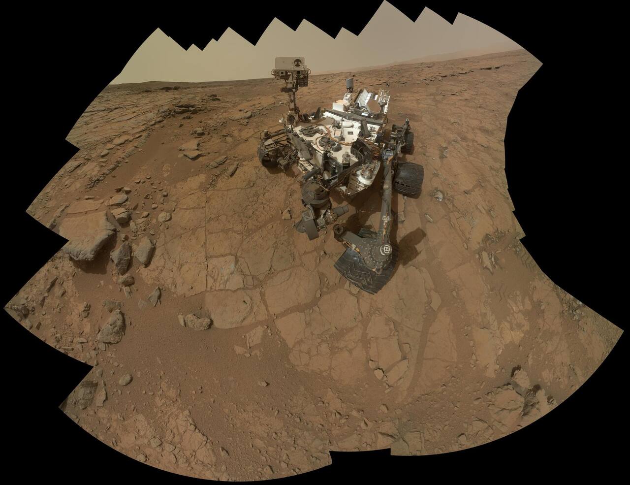 NASA/JPL-Caltech/MSSS. Public domain (NASA / US government work).
Overview
Section titled “Overview”Curiosity is a six-wheeled nuclear-powered rover carrying an onboard sample-processing laboratory. The mission objective was to determine whether its landing site had ever offered conditions suitable for microbial life.
Specifications
Section titled “Specifications”| Parameter | Value |
|---|---|
| Total mass | 899.2 kg |
| Width / length | 2.8 m / 3.0 m |
| Length with arm extended | 4.7 m |
| Top deck height / total height | 1.1 m / 2.2 m |
| Arm reach, body front to turret center | 1.9 m |
Values from [2].
The mission page gives the arm reach as about 2.2 m and the vehicle as 10 feet long, 9 feet wide and 7 feet tall [19], against the 1.9 m turret-center reach and the 3.0 by 2.8 by 2.2 m envelope in the flight system description [2].
Mission profile
Section titled “Mission profile”| Parameter | Value | Source |
|---|---|---|
| Launch | 26 November 2011 | [19] |
| Landing | 6 August 2012, Gale crater, 4.5965 S, 137.4019 E | [13] |
| Landing dispersion | 2.385 km downrange of the aim point | |
| Entry mass | 3257 kg | [5] |
| Landed mass | 850 kg | |
| Instrument payload carried | 75 kg | [2] |
| Aeroshell | 4.5 m diameter, 70 degree sphere-cone | |
| Samples analyzed through sol 2844 | 33 drilled rock and scooped soil samples | [4] |
| Stratigraphic section climbed through sol 2844 | about 330 m | |
| Drilled samples to date | 42 | [19] |
| Elevation gained on Mount Sharp | 1 km, marked 26 August 2026 |
The mission page gives 42 powderized rock samples taken with the arm drill and an elevation gain of 1 km up Mount Sharp reached on 26 August 2026 [19], against the 33 samples and roughly 330 m of section recorded through sol 2844 in the peer-reviewed mission summary [4]; the two differ in date.
Entry mass of 3257 kg against 836 kg for a Mars Exploration Rover put the vehicle outside the airbag mass range, and the landing system became a guided lifting entry at a hypersonic lift-to-drag ratio of 0.24 and a ballistic coefficient of about 140 kg/m2, followed by a 19.7 m Disk-Gap-Band parachute deployed at Mach 2.05, heatshield jettison near Mach 0.7, and powered descent on eight monopropellant Mars Lander Engines throttling over 400 to 3000 N [5]. At 17 m above ground level and 0.75 m/s the descent stage lowered the rover on three 7.5 m bridles [5] and held 0.75 m/s until bridle line force indicated touchdown. Lowering on bridles rather than landing the whole assembly keeps the descent engines roughly 7.5 m above the surface at touchdown and avoids plume-driven regolith erosion under the wheels.
The flown EDL matched the pre-flight Monte Carlo, which comprised 682 random dispersions across 4834 cases: every Timeline Engine event occurred within 6.9089 s of its predicted mean time, and reconstructed parachute deploy conditions were within 0.75 sigma in Mach number, 0.02 sigma in dynamic pressure and 0.14 sigma in altitude [13]. Entry interface was reached 3.5 km higher and 7.8 km further from the target than the expected mean, a 3.8 sigma excursion the entry guidance absorbed through three bank reversals at t = 612.875, 633.875 and 663.375 s.
Mobility
Section titled “Mobility”| Parameter | Value | Source |
|---|---|---|
| Configuration | 6-wheel drive, 4-wheel steer, rocker-bogie | [2] |
| Wheel diameter | 0.5 m | |
| Belly clearance on flat ground | 0.66 m | |
| Obstacle capability | approximately one wheel diameter | |
| Tilt limit, structural | 50 deg any direction without overturning | [3] |
| Tilt limit, fault protection | 30 deg | [2] |
| Actuator reduction | 1024:1 four-stage planetary | [1] |
| Actuator rating | 10 A, 1000 Nm | |
| Drive current software limit | 5.25 A | |
| Steer current software limit | 4.5 A | |
| Peak observed actuator current, first seven years | 4.422 A | |
| Design life requirement | 20 km | [4] |
Each wheel and steering actuator assembly contains a brushless DC motor, a brake and an incremental encoder [1]. The motor controller assembly carries eight driver boards and can energize eight of the rover’s thirty-eight motors at once, fewer than the ten wheel and steering assemblies, so mobility executes as steer-then-drive: the rover steers, sets the steering brakes, then drives, and encoders on the idle set are not monitored during the other phase.
Drives are composed from two primitives, a constant-curvature arc and a turn in place. Arcs are open-loop and terminate on wheel revolutions rather than on measured pose; 81.0 percent of the 22,312 arcs commanded in the first seven years were straight [1]. Turns in place close the loop on the IMU. Over the first seven years Curiosity drove 21,318.5 m, with individual sol drives from 2.6 cm to 142.5 m and a mean of 28.9 m [1], [11]. Commanded motion split 72.7 percent forward, 18.4 percent backward and 8.9 percent turning in place.
Wheel damage was first confirmed from imaging on sols 488 to 490 [4]. Embedded rocks punctured the thin aluminum wheel skins earlier than predicted, because a rock fixed in bedrock does not yield and the full wheel load concentrates on it [7]. The specific mechanism is a suspension load path: five wheels build up load within the rocker-bogie that pushes against a sixth which has encountered a sharp obstacle. Backward driving was increased on sol 546 in response, then reduced again on sol 671 because it did not lower the damage rate and cost drive distance within the allotted time [1].
Mars Yard tests on the Scarecrow rover and Artemis simulations showed resultant forces up to twice the static wheel load when a wheel on a leading suspension arm meets a sharp immobile rock while all six drive actuators hold their commanded velocities. Punctures of the 0.75 mm aluminum skin need roughly 800 to 1000 N against the sharpest rocks, and static loads are only 458 to 636 N, so the load transfer rather than the static load crosses the threshold [7].
The durable fix was software. Terrain-adaptive wheel speed control uses measured attitude rates and rocker and bogie angles to estimate each wheel’s contact angle, then commands each wheel’s speed at 8 Hz so that wheels not currently climbing slow rather than pushing the climbing wheel into the rock [1], [10]. It was approved for nominal use on sol 1678; since then 99.48 percent of odometry has been driven with it enabled, at a cost of roughly 10 percent longer drives and about double the drive motor telemetry volume. It reduced mean and standard deviation of heading error on straight arcs by 41 percent, and reduced internal suspension loads as measured on the vehicle [4]. The algorithm was a hot-patch flight software change deployed in 2017, and its authors compared 3.6 km of flight telemetry before and after activation with Scarecrow and vehicle system test bed results [10].
Damage is concentrated on the middle wheels and the left front wheel; the other three show little [4]. Two grousers had broken on the left middle wheel by sol 1641 and one on the right middle wheel by sol 2407. A JPL wheel and suspension test rig driven over analog Gale terrain established that a wheel with three broken grousers retains approximately 40 percent of its life, which put the flight wheels at sol 2844 at 16 km of remaining life each and at least 39 km in total, against the 20 km design requirement [4]. Rimmed wheel designs were subsequently evaluated on the Scarecrow mobility testbed [8], and terrain physical properties along the traverse were derived from combined orbital and surface data [9].
Power and energy
Section titled “Power and energy”| Parameter | Value | Source |
|---|---|---|
| Source | MMRTG | [2] |
| Electrical output at start of landed mission | approx 110 W | |
| DOE best estimate, start of surface ops to end of mission | 114 W to 108 W | [3] |
| Batteries | two lithium-ion, approx 42 A-h each | [2] |
| Battery discharge requirement | up to 555 Wh in one sol, 670 cycles from full charge | [3] |
| Available energy | approx 2500 Wh per sol |
Output is thermal rather than photovoltaic, so generation is independent of season, dust opacity and time of day, which removes the dust-storm and winter-solstice power constraints that governed the Mars Exploration Rovers [3]. Peak rover loads exceed generator output, so the batteries buffer the difference and a deep discharge was not expected more than once per sol.
Two quantities decay together over the mission: MMRTG output per sol and battery capacity. Load energy has stayed roughly constant, so the battery is discharged to a lower state of charge each sol and less energy is shunted to the environment as excess [4]. The operational consequence is longer recharge intervals between drives rather than an outright loss of capability [1], moving toward reductions in energy use and additional time dedicated to charging.
The generator’s power prediction was checked against measurement three times before launch and once after landing, and the power agreed at every point while the thermal condition assumed for it did not. Post-fueling, flight unit F1 was predicted at 110.7 W at a 28 V bus with a fin root temperature of 132 C and measured 111.2 W at 31.4 V with the fin root at 90 C; at launch it measured 113.9 W at 32.9 V with the fin root at 96 C against 109.1 W predicted at 28 V and a fin root of 180 C [24]. About five hours after the heat rejection system vent on the surface, output was roughly 115 W with the rover bus at 31 to 32.7 V, against 106.3 W predicted for surface operations in spring at the median temperature case, 29 V and a fin root of 175 C. Reconciling three independent prediction engines, after the pre-fueling model was found to over-predict, left an uncertainty band of 6 percent at the start of the surface mission widening to 10 percent.
Thermal
Section titled “Thermal”The rover was designed to land anywhere between 45 N and 45 S, where surface temperatures range from about +40 C to -127 C, the CO2 frost point at Martian surface pressure, with diurnal swings up to 145 C [3].
| Requirement | Value | Source |
|---|---|---|
| Avionics mounting plate and payload module held at or above | 20 C for at least 6 h per sol | [3] |
| Plate minimum throughout the sol, worst case (winter at 45 S) | -40 C | |
| Daily cycle limit on hardware | ±30 C | |
| Mobility actuator minimum before actuation | -55 C (wet lubricant) | [1] |
Three mechanisms achieve this: internal dissipation, electrical heaters on specific components, and a heat rejection system built from two mechanically pumped fluid loops, the rover loop and the cruise loop, thermally coupled to each other during cruise [3], [14]. The working fluid in both is Freon, CFC-11. The rover loop moves heat from the generator to the electronics when it is cold and from the electronics straight to the environment when it is warm; the generator produces about 110 W of electrical power and roughly 2000 W of waste heat [12]. MMRTG waste heat is harvested through a pair of heat exchangers that surround the generator at the aft end of the rover: honeycomb-core sandwich panels with hand-bent aluminum HRS tubing bonded to both faces, built with aluminum facesheets and aerogel inside a composite honeycomb core so that in-plane conductivity is high and through-thickness conductivity very low. The MMRTG-facing surface acquires heat and the outward surface rejects it, and the two surfaces must sit at very different temperatures for the loops to work, which is what the aerogel core buys.
Over the first 204 sols most internal box temperatures landed within 2 to 5 C of pre-landing predictions [30]. Measured atmosphere temperature ran up to 25 C warmer by day than the circulation model predicted, which the authors attribute to the 170 C MMRTG warming the air near the rover, and warmup heater predictions were conservative [30].
Mobility actuators are a separate thermal case because their wet lubricants should be above -55 C before actuation [1]. Platinum resistance thermometers on each actuator feed closed-loop heating, controlled for all drive actuators from a single drive thermometer and all steer actuators from a single steer thermometer. There are two mobility heater circuits; using the backup requires swapping from the prime to the backup power and analog module. Preheat duration is predicted from thermal models when a drive is scheduled, because preheating consumes both energy and clock time.
Compute and avionics
Section titled “Compute and avionics”| Parameter | Value | Source |
|---|---|---|
| Processor | BAE RAD750, PowerPC 750 architecture, radiation hardened | [1] |
| Clock | 133 MHz | |
| RAM | 512 MB | |
| Operating system | VxWorks | |
| Non-volatile storage | 32 Gbit on the NVMCAM card | [3] |
| Backplane | CompactPCI | |
| Command and data bus | MIL-STD-1553 | |
| Redundancy | two rover compute elements, one active |
The two rover compute elements are operated one at a time with the spare in cold backup, except during entry, descent and landing when the second acts as a hot backup [3]. Power switching and analog input and output are handled by redundant rover power and analog modules connected to the RCEs over MIL-STD-1553.
Cross-strapping is partial. Each engineering camera pair is wired to one computer: RCE-A carries one set of hazard cameras and RCE-B the other, so switching to the backup cameras requires switching computers [1].
RCE-A was prime at landing. A failing region of RCE-A NAND flash on sol 200 removed half of that side’s flash from use and forced a swap to RCE-B on sol 201 [1], [4]. RCE-B ran the mission until sol 2173, when its data-product partition failed to mount; the team switched back to RCE-A on sol 2188 and stayed there until the RCE-B partition had been reformatted on sol 2342. Cumulative driving splits 1158.793 m (5.63 percent) on RCE-A, over sols 15 to 166 and 2250 to 2338, against 20,159.565 m (94.37 percent) on RCE-B [1]. Unexpected flight software resets on sols 2320 and 2339 led the project to declare the remaining A-side flash unreliable and to withdraw the A side from nominal science operations; a build was developed to give the A side cross-string diagnostics and the ability to keep the rover safe indefinitely while the B side is recovered, installed on sol 2963. Loss of rover flash memory remains one of the mission’s four top unrealized internal risks. The recovery build, R-Hope, abandons the A-side NAND flash and relocates the file system into half of the 128 MB NOR flash that had held four redundant flight software copies [28]. File system volume falls by about 99 percent, from 2 GB to 64 MB, no previous flight software copy can be held, and a full partition reformat takes 45 minutes against under 5 minutes on NAND [28].
The 133 MHz processor bounds visual navigation throughput [1]. Acquiring, processing and writing the data products for one visual odometry stereo pair takes 47 s on average, a figure set jointly by the processor, the operating system, the camera and camera interface design, and flash write time [1]. The verification campaign for running visual odometry concurrently with driving, rather than stopping to compute, is documented separately [12].
Autonomy
Section titled “Autonomy”Light time and relay latency preclude real-time intervention during a drive, so the rover carries three onboard layers: visual odometry, hazard detection and avoidance, and visual target tracking [1]. Fault protection trip thresholds are parameters set per drive by human rover planners. The flight software fault protection engine arbitrates over 1000 monitors and 39 system responses, polling monitor states once per second and running the highest-priority response; monitors latch until reset, which keeps a polling design free of races at the cost of chronological ordering, so the root-cause monitor is not necessarily serviced first [25].
Visual odometry tracks features between stereo pairs to measure actual against commanded motion, which is what makes slip observable [2]. Three modes are available: slip check, which takes a stereo pair every 20 m to bound accumulated error with no imagery in between; full mode, imaging throughout; and VO auto, in which the rover switches between the two according to local terrain, motor current, angular rate during turns in place, and measured slip [1].
Science targeting is a second autonomous function. AEGIS, used 54 times over sols 1343 to 1663, selects ChemCam targets after a drive; once the target profile was updated it placed all laser points on the preferred outcrop material for 44 of 47 targets, against 10 of 42 for modeled blind targeting, with 150 to 450 s of runtime on the RAD750 [26].
Path selection is commandable separately from odometry mode.
| Mode | Behavior | Source |
|---|---|---|
| Directed | follows the commanded path | [1] |
| Guarded | heads for the goal, consults the onboard world map, stops on keep-out zone or geometric hazard | |
| AvoidKOZ | routes around manually specified keep-out zones only | |
| AutoNav | routes around both geometric hazards and keep-out zones, building the world map as it goes | [1][2] |
Modes mix within a sol: a drive commonly runs directed to a first waypoint, then switches to VO auto plus AutoNav to extend the traverse into terrain the planners could not assess [1]. With global path planning enabled, AvoidKOZ and AutoNav plan in a 2.5-dimensional world model without predicting suspension configuration. On sol 385 Curiosity drove 141.5 m, 5 m further than predicted, because AutoNav routed around hazardous terrain near the end of the drive [1]. Onboard image-based path tracking is also used to reduce positional uncertainty and so support the route-level avoidance of wheel-damaging terrain [4].
Communications
Section titled “Communications”| Link | Parameter | Value |
|---|---|---|
| X-band DTE/DFE | Amplifier | 15 W SSPA through gimballed HGA or rover LGA [3] |
| X-band downlink | Coding | turbo, rates 1/2, 1/3, 1/6 [3] |
| X-band downlink | Information rates | 10 bps to 62,500 bps [3] |
| X-band downlink | Symbol rate cap | 300,000 sps [3] |
| X-band downlink | Frame | 1784 bits, interleave depth 1, code efficiency 0.86 [3] |
| X-band downlink | Rate at maximum Earth range, 34 m station | approx 160 bps [3] |
| X-band uplink | Emergency rate through rover LGA, 70 m station | 7.8125 bps [3] |
| UHF relay | Transponders | two Electra-Lite, more than 8.5 W out of the diplexer [3] |
| UHF return | Rates | 2 kbps to 2048 kbps, effective throughput capped near 1.35 Mbps [3] |
| UHF forward | Rates | 2 to 256 kbps; 32 kbps baselined for MRO [3] |
| UHF channels | Return / forward channel 0 | 401.585625 MHz / 437.1 MHz [3] |
The 300,000 sps symbol rate cap excludes the combination of 62,500 bps with rate 1/6 [3]. The 0.86 code efficiency against 0.58 on MER is worth 1.7 dB, which mainly benefits the lowest rates.
Orbiter capability differs by radio. With MRO the return link uses suppressed carrier and adaptive data rate, in which the Proximity-1 protocol renegotiates rate during the pass. Odyssey, whose CE505 radio supports only 8, 32, 128 and 256 kbps, uses residual carrier at a fixed rate per contact, and only 8 and 32 kbps are available on its forward link [3]. Two alternate channels each are held in reserve against electromagnetic interference on MRO. Proximity-1 sequence-controlled transfer is nominal; unacknowledged bit-stream mode was used for entry, descent and landing, where MSL broadcast at 8 kbps [3].
MRO flies a Sun-synchronous orbit crossing at 15:00 local mean solar time, with a pass pattern repeating every 17 sols, delivering 30 to 600 Mbit per pass and 100 to 1150 Mbit per sol, against a requirement of 250 Mbit per sol over two passes [3]. Loss of a relay orbiter, MRO or Odyssey in particular, is the mission’s principal external risk, because the pace of operations depends on their consistent afternoon overflights [4].
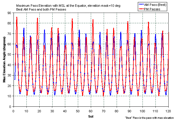
Maximum MRO pass elevation angle against sol for a rover at the equator, 10 degree elevation mask [3]. The beat between the 17-sol MRO ground track repeat and the sol sets the day-to-day variation in achievable relay volume that the tactical cycle has to budget against. Source: [3]. Public domain (NASA).
Surface operations use X-band for uplink and UHF for downlink, with relay uplink available [3]. The generalized telecom predictor is run daily as part of the tactical process, because relay volume prediction gates what can be planned.
Communication behavior is table-driven: a primary table of up to 256 communication windows for standard operations and a separate high-priority table for anomalies [3]. Flight software blocks activities that would generate radio frequency interference during a window. The remote engineering unit in the power and analog module stays powered whenever the rover sleeps and is redundantly connected to both Electra-Lite radios, so an orbiter hail can wake the rover.
Payload and instruments
Section titled “Payload and instruments”The arm is a 5 degree-of-freedom manipulator of 70 kg mass, reaching 1.9 m from the front of the rover body to the turret center when fully extended [2]. The turret is 0.6 m in diameter and 30 kg, carrying five devices: the APXS and MAHLI contact instruments, the Powder Acquisition Drill System, the Dust Removal Tool, and CHIMRA.
| Instrument | Key parameters | Source |
|---|---|---|
| ChemCam | 1067 nm laser, 350 to 550 um spot at up to 7 m standoff, 10 Hz; 242 to 800 nm spectrometers at 0.2 nm FWHM below 500 nm and 0.65 nm above; mast unit 5778 g, body unit 4789 g with TEC | [15] |
| MAHLI | 1600 x 1200 pixels at 7.4 um, 18.4 mm focal length, working distance 2.1 cm to infinity, approx 14 um/pixel at closest focus, white and 365 nm UV LEDs, 8 GB non-volatile memory, 0.578 kg camera head | [16] |
| CheMin | cobalt X-ray tube at 28 keV and 100 uA, approx 70 um collimated beam, 5 to 50 deg 2-theta at better than 0.35 deg, CCD 600 x 582 at 40 um and 1 to 15 keV, 27 reusable Mylar or Kapton windowed cells | [17] |
| SAM | 40 kg suite; 74 sample cups of which 59 quartz for evolved gas analysis and 9 foil-topped for wet chemistry; pyrolysis to 900 C nominal and 1100 C with the auxiliary heater; QMS 2 to 535 Da; six GC columns; helium carrier at 0.03 atm-cc/s | [18] |
ChemCam thermal design is set by the fiber optic run from mast to body: the fiber survives -130 to +110 C but operates only over -90 to +50 C, and the body unit spectrometer CCDs are held by 3 W thermo-electric coolers within a -40 to +50 C envelope [15]. CheMin’s CCD is operated at -60 C by design and ran between -48 C and -22 C on Mars [17]. Cell window material is a deliberate split: Mylar gives a flat diffraction background across the full 2-theta range but is less durable than Kapton under vibration, so both types are carried on the sample wheel.
Mast-mounted instruments are the Mast Camera pair and ChemCam. Environmental and radiation monitoring is by REMS, RAD and the DAN neutron spectrometer. REMS wind sensors on boom 1 were inoperable on landing and boom 2 sensors were only partially operational until about sol 1500; the suspected cause, landing debris or blowing sand, could not be confirmed at the available imaging resolution [4]. The DAN active neutron generator operates past its expected life at reduced output.
Sample acquisition
Section titled “Sample acquisition”| Parameter | Value | Source |
|---|---|---|
| Drill bit | 5/8 in (approx 1.6 cm) commercial hammer drill bit in a thick-walled tube | [6] |
| Hole geometry | 1.6 cm diameter, up to 5 cm deep | [2] |
| Percussion rate | 1800 blows per minute | [6] |
| Percussion impact energy, variable | 0.05 to 0.8 J | |
| Weight on bit during acquisition | 120 N | |
| Spare bits | two, in bit boxes on the rover front panel | [2] |
| Scoop depth / volume | up to 3.5 cm / 1 to 30 cm3 | |
| CHIMRA sieve meshes | less than 150 um, and less than 1 mm | |
| Portion volume to SAM via the 1 mm path | 45 to 130 mm3 | |
| Sample drop-off air gap into the instrument funnel | 2 to 5 cm |
Powder travels up an auger in the drill into a chamber connected by transfer tube to CHIMRA, and through CHIMRA by gravity, changing the arm position and orientation, plus vibration [2]. The percussion mechanism supplies both the impact that breaks the rock and the vibration that moves powder through the bit assembly [6]. The drill chuck mechanism releases worn bits and takes fresh ones from the bit boxes, and was required to release a bit while loaded by the worst case of complete rover slip on a Martian slope. The 2 to 5 cm vertical air gap the portion crosses on its way into the instrument funnel is exposed to wind, so a wind guard was added [6]. Five Organic Check Material canisters are mounted on the rover front for contamination control.
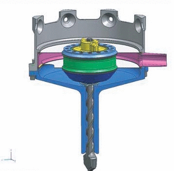
Cross section of the drill bit assembly. Rotation and percussion are transmitted down the bit through a dirt-tolerant torque coupling that accommodates axial, radial and angular motion between spindle and bit; powder travels up the flutes into the chamber above. Diaphragms radially constrain the rotating bit and form the dust seal. Source: [6]. Public domain (NASA).
Three mechanism failures have reshaped sampling. The percussion mechanism carried a known pre-launch flaw that could produce electrical shorts; the first occurred on sol 911 during sample transfer from drill to CHIMRA, and the response was to raise onboard fault thresholds to tolerate low-current shorts and patch the motor controller software to protect sensitive electronics and monitor currents during percussion [4]. The CHIMRA tunnel motor, used to inspect and clean the 150 um sieve, stalled on sol 1231; the stall has not repeated and use limits were imposed. The drill feed motor stalled on sol 1536 at Precipice and was declared unreliable. Feed retraction is required to move collected material into CHIMRA, and a permanent failure in the retracted state would have left the drill unable to extend past its stabilizer posts to reach the surface at all. The project therefore developed Feed-Extended Drilling and Feed-Extended Sample Transfer, which keep the feed fully extended and portion sample with small pulses of rotation and percussion, delivering material directly from the drill and bypassing CHIMRA, so FEST portions are unsieved. Twelve of the 33 samples analyzed through sol 2844 were acquired after the anomaly [4]. The feed anomaly took eighteen months of flight diagnostics and bench work to localize to a high-friction zone about one third of a motor revolution wide at a fixed clocking angle, best explained by the ferrous brake plate partially disengaging [29]. Rotary-only drilling, developed as a hedge against losing percussion altogether, makes steady progress for 10 to 30 mm in analog mudstones and sandstones and then becomes extremely slow [4].
The sampling chain was designed as a serial seven-step pipeline of acquire, sieve, portion, deliver, repeat, dump and clean, and over more than 1500 sols it became a sampling network, extended through ground and flight scripting without flight software updates [31], [33].
Modes of operation
Section titled “Modes of operation”Surface activity is organized by sol, the Martian day of 24 h 39 min 35 s [3]. Within a sol the rover executes an uplinked sequence covering imaging, arm work, instrument operation, driving and communication windows, generating continuous engineering housekeeping telemetry and episodic event records buffered for the next pass.
Safe mode is entered when flight software detects an anomaly: the rover abandons the current plan and the prime RCE reboots into a minimal configuration [1]. Three planned drives were lost this way in the first seven years, on sols 697, 1391 and 2340; the sol 1391 case followed a flight software consistency check failing on sol 1389.
In safe mode the rover follows a fixed table of fault protection communication windows. Curiosity is power negative whenever the compute element is on, so window length trades communication against recharge: nine Martian hours per sol gained 22 percent state of charge at landing, and the 6.6 hours that could be afforded by 2023 gained 5.5 percent [32].
Below safe mode is a graded set of mobility fault responses.
| Drive outcome statistic, first seven years | Value |
|---|---|
| Attempted drives | 738 |
| Ran to completion | 622 |
| Stopped early or never started | 116 |
| Predicted cumulative odometry still achieved | 91.7 percent |
| Distinct fault categories that have stopped a drive | 24 (16 mobility, 8 general fault protection) |
| Faults that were expected rather than anomalous | 29 |
| Of those, the time-of-day limit | 26 |
Counts from [1].
The time-of-day limit is a deliberate cutoff so that post-drive imaging and the relay pass still fit in the plan, and autonomous drives are routinely commanded to run until it so that they cover as much ground as the allocation permits [1]. Relay volume prediction feeds that allocation directly [3]. The remaining expected faults were single occurrences of exceeding the slip limit (sol 983), the tilt limit (sol 151) and entering a keep-out zone (sol 163).
The rover maintains four mobility error states: mobility goal error, mobility motion error, mobility precluded, and DO MOBILITY false [1]. A time-of-day fault clears its own error state so that the scripted post-drive turn to a communications-favorable heading still runs; most other faults require ground intervention to clear, and 81.0 percent are cleared within a sol or two. DO MOBILITY is set false by an unstowed arm, an open MAHLI lens cover, an unstowed Mast Camera focus mechanism, CheMin or SAM in use, or ChemCam outside its Sun-tolerant focus range, which is how instrument state interlocks against driving [15]. Fault responses are themselves parameters: after five occurrences of a detected MMRTG short blocking a drive, the team set the short response parameter to ignore for all steer and drive actuators on sol 1309.
Ground operations
Section titled “Ground operations”Curiosity is operated from JPL on a two-tier cycle. A strategic team works weeks to months ahead, using HiRISE imagery from MRO, which orbits between 255 and 320 km and resolves about 0.3 m per pixel at 300 km, to recommend routes that balance science targets against terrain risk [1]. Strategic route planning is also the primary control on wheel damage rate, avoiding terrain assessed as risky at the route level rather than only at the drive level [4]. Tactical rover planners build each sol’s drive from a high-resolution terrain mesh generated from NavCam stereo acquired at the end of the previous drive, and may depart from the strategic route where the closer imagery reveals a hazard.
The tactical product is a command sequence, simulated before uplink in the Rover Sequencing and Visualization Program, which also produces the predicted odometry against which the executed drive is later compared [1]. Because the sol is 39 minutes longer than an Earth day, a planning cycle locked to the rover’s local time walks through the terrestrial clock; the team worked that shifting schedule during early surface operations before moving to an Earth-aligned cycle.
Drilling has its own approval gate. Before each attempt the team assesses rover stability against drilling forces and dynamics, the safety of the drill against the target, the risk that drilling displaces or fractures the rock and so removes the pressure needed to force cuttings into the drill stem, and the possibility that the powder will clog or stick to hardware given its composition; approval comes from a group of engineers, scientists and project management [4]. Given the prevalence of small blocks and highly fractured outcrops, the team has on several occasions accepted that acquisition may not complete, provided risk to hardware is ruled out.
Productivity is bounded by planning constraints more than by hardware. Across three campaigns only 25 to 42 percent of sols made significant direct progress on campaign objectives, and flight computer duration and energy came in 12 to 15 percent and 5 to 11 percent under prediction [27].
Ground segment failures propagate directly into lost science. Seven planned drives were never attempted because the plan did not reach the rover, including sols 1068 to 1070, lost to a complex-wide power outage at the Madrid Deep Space Network site [1]. A further six were withdrawn before uplink, typically after downlink revealed that a prior sol’s activity had failed. Hardware is inspected on a schedule as well as on event: the center differential pivot close-out plate is imaged annually and its sixteen fasteners checked for movement, after loosening was found on the Scarecrow test rover.
Technologies developed
Section titled “Technologies developed”Sky crane landing, radioisotope surface power with a pumped-loop thermal system, and onboard sample analysis were all first flown here, and Perseverance inherited the chassis, mobility system and landing architecture [5].
Terrain-adaptive wheel speed control established that wheel damage from embedded rocks is controllable in software on an already-built vehicle, by modulating per-wheel speed from suspension kinematics [1], [10]. The wheel life model derived from the JPL suspension test rig, which relates broken grouser count to remaining wheel life, gives a quantitative basis for route selection rather than a qualitative one [4]. Feed-Extended Drilling and Feed-Extended Sample Transfer demonstrated that a rotary-percussive sampling chain can be reconfigured in flight to operate with a failed feed actuator and without its sieving and portioning stage. Visual odometry work led to running visual odometry concurrently with driving rather than stopping to compute, removing the stop-and-think duty cycle that had limited MER and MSL drive rates [12]. The operational pattern is now standard for Mars surface robotics: strategic route planned from orbital imagery, tactical sequences built and simulated daily from the rover’s own stereo imagery, and layered onboard fault protection parameterized per drive [3].
What is not established
Section titled “What is not established”Cumulative totals on the mission page are undated snapshots without a stated basis [19], and the last distance with both a date and a peer-reviewed source is 21.3185 km at sol 2488. Soil cohesion, friction angle and shear modulus for the Gale terrains are fitted values that reproduce observed sinkage and slip, not measurements, and sinkage under about 1 cm sits at the resolution limit of stereo wheel-track analysis [8]. Wheel life remaining rests on a test-rig relation between broken grousers and life, not on flight measurement beyond sol 2844 [4]. The long-term reliability of the A-side computer and the feed-extended sampling chain has no flight record beyond the dates cited.
References
- Rankin, A., Maimone, M., Biesiadecki, J., Patel, N., Levine, D. and Toupet, O. (2021). Mars Curiosity Rover Mobility Trends During the First Seven Years
. Journal of Field Robotics, 5. Source
BibTeX
@article{rankin2021mars, title = {Mars Curiosity Rover Mobility Trends During the First Seven Years}, author = {Rankin, Arturo and Maimone, Mark and Biesiadecki, Jeffrey and Patel, Nikunj and Levine, Dan and Toupet, Olivier}, journal = {Journal of Field Robotics}, volume = {38}, number = {5}, pages = {759--800}, year = {2021}, doi = {10.1002/rob.22011}, abstract = {Abstract NASA's Mars Science Laboratory (MSL) Curiosity rover landed on Mars on August 6, 2012. In the 7 years between landing and August 6, 2019 (sol 2488), Curiosity has driven 21,318.5 m over a variety of terrain types and slopes, employing multiple drive modes with varying amounts of onboard autonomy. Curiosity's drive distances each sol have ranged from its shortest drive of 2.6 cm to its longest drive of 142.5 m, with an average drive distance of 28.9 m. Real‐time human intervention is not possible during Curiosity's drives due to the latency in uplinking commands and downlinking telemetry. Instead, the operations team relies on Curiosity's fault protection, autonomous navigation, and visual odometry software to keep the rover safe during drives. During its first 7 years on Mars, Curiosity has attempted 738 drives. While 622 drives ran to completion, 116 drives were prevented or stopped early by Curiosity's fault protection software. The primary risks to mobility success have been wheel damage, wheel entrapment, progressive wheel sinkage, and the potential for hardware or cable failures that result in an inability to command one or more steer or drive actuators. In this paper, we describe Curiosity's mobility subsystem, mobility trends over the first 21.3 km of the mission, operational aspects of mobility fault protection, risks to continued mobility success, and risk mitigation strategies.} } - Grotzinger, J. P., Crisp, J., Vasavada, A. R., Anderson, R. C., Baker, C. J., Barry, R., Blake, D. F., Conrad, P., Edgett, K. S., Ferdowski, B., Gellert, R., Gilbert, J. B., Golombek, M., Gómez-Elvira, J., Hassler, D. M., Jandura, L., Litvak, M., Mahaffy, P., Maki, J., Meyer, M., Malin, M. C., Mitrofanov, I., Simmonds, J. J., Vaniman, D., Welch, R. V. and Wiens, R. C. (2012). Mars Science Laboratory Mission and Science Investigation
. Space Science Reviews. Source
BibTeX
@article{grotzinger2012mars, title = {Mars Science Laboratory Mission and Science Investigation}, author = {Grotzinger, John P. and Crisp, J. and Vasavada, Ashwin R. and Anderson, R. C. and Baker, C. J. and Barry, R. and Blake, David F. and Conrad, P. and Edgett, Kenneth S. and Ferdowski, B. and Gellert, Ralf and Gilbert, J. B. and Golombek, M. and Gómez-Elvira, J. and Hassler, Donald M. and Jandura, Louise and Litvak, Maxim and Mahaffy, P. and Maki, J. and Meyer, M. and Malin, Michal C. and Mitrofanov, Igor and Simmonds, John J. and Vaniman, D. and Welch, R. V. and Wiens, Roger C.}, journal = {Space Science Reviews}, volume = {170}, pages = {5--56}, year = {2012}, doi = {10.1007/978-1-4614-6339-9_3}, abstract = {Scheduled to land in August of 2012, the Mars Science Laboratory (MSL) Mission was initiated to explore the habitability of Mars. This includes both modern environments as well as ancient environments recorded by the stratigraphic rock record preserved at the Gale crater landing site. The Curiosity rover has a designed lifetime of at least one Mars year (∼23 months), and drive capability of at least 20 km. Curiosity’s science payload was specifically assembled to assess habitability and includes a gas chromatograph-mass spectrometer and gas analyzer that will search for organic carbon in rocks, regolith fines, and the atmosphere (SAM instrument); an x-ray diffractometer that will determine mineralogical diversity (CheMin instrument); focusable cameras that can image landscapes and rock/regolith textures in natural color (MAHLI, MARDI, and Mastcam instruments); an alpha-particle x-ray spectrometer for in situ determination of rock and soil chemistry (APXS instrument); a laser-induced breakdown spectrometer to remotely sense the chemical composition of rocks and minerals (ChemCam instrument); an active neutron spectrometer designed to search for water in rocks/regolith (DAN instrument); a weather station to measure modern-day environmental variables (REMS instrument); and a sensor designed for continuous monitoring of background solar and cosmic radiation (RAD instrument). The various payload elements will work together to detect and study potential sampling targets with remote and in situ measurements; to acquire samples of rock, soil, and atmosphere and analyze them in onboard analytical instruments; and to observe the environment around the rover. The 155-km diameter Gale crater was chosen as Curiosity’s field site based on several attributes: an interior mountain of ancient flat-lying strata extending almost 5 km above the elevation of the landing site; the lower few hundred meters of the mountain show a progression with relative age from clay-bearing to sulfate-bearing strata, separated by an unconformity from overlying likely anhydrous strata; the landing ellipse is characterized by a mixture of alluvial fan and high thermal inertia/high albedo stratified deposits; and a number of stratigraphically/geomorphically distinct fluvial features. Samples of the crater wall and rim rock, and more recent to currently active surface materials also may be studied. Gale has a well-defined regional context and strong evidence for a progression through multiple potentially habitable environments. These environments are represented by a stratigraphic record of extraordinary extent, and insure preservation of a rich record of the environmental history of early Mars. The interior mountain of Gale Crater has been informally designated at Mount Sharp, in honor of the pioneering planetary scientist Robert Sharp. The major subsystems of the MSL Project consist of a single rover (with science payload), a Multi-Mission Radioisotope Thermoelectric Generator, an Earth-Mars cruise stage, an entry, descent, and landing system, a launch vehicle, and the mission operations and ground data systems. The primary communication path for downlink is relay through the Mars Reconnaissance Orbiter. The primary path for uplink to the rover is Direct-from-Earth. The secondary paths for downlink are Direct-to-Earth and relay through the Mars Odyssey orbiter. Curiosity is a scaled version of the 6-wheel drive, 4-wheel steering, rocker bogie system from the Mars Exploration Rovers (MER) Spirit and Opportunity and the Mars Pathfinder Sojourner. Like Spirit and Opportunity, Curiosity offers three primary modes of navigation: blind-drive, visual odometry, and visual odometry with hazard avoidance. Creation of terrain maps based on HiRISE (High Resolution Imaging Science Experiment) and other remote sensing data were used to conduct simulated driving with Curiosity in these various modes, and allowed selection of the Gale crater landing site which requires climbing the base of a mountain to achieve its primary science goals. The Sample Acquisition, Processing, and Handling (SA/SPaH) subsystem is responsible for the acquisition of rock and soil samples from the Martian surface and the processing of these samples into fine particles that are then distributed to the analytical science instruments. The SA/SPaH subsystem is also responsible for the placement of the two contact instruments (APXS, MAHLI) on rock and soil targets. SA/SPaH consists of a robotic arm and turret-mounted devices on the end of the arm, which include a drill, brush, soil scoop, sample processing device, and the mechanical and electrical interfaces to the two contact science instruments. SA/SPaH also includes drill bit boxes, the organic check material, and an observation tray, which are all mounted on the front of the rover, and inlet cover mechanisms that are placed over the SAM and CheMin solid sample inlet tubes on the rover top deck.} } - Makovsky, A., Ilott, P. and Taylor, J. (2009). Mars Science Laboratory Telecommunications System Design
. Jet Propulsion Laboratory, California Institute of Technology, Article 14. Source
BibTeX
@techreport{makovsky2009mars, title = {Mars Science Laboratory Telecommunications System Design}, author = {Makovsky, Andre and Ilott, Peter and Taylor, Jim}, series = {DESCANSO Design and Performance Summary Series}, number = {Article 14}, institution = {Jet Propulsion Laboratory, California Institute of Technology}, year = {2009}, url = {https://descanso.jpl.nasa.gov/DPSummary/Descanso14_MSL_Telecom.pdf} } - Vasavada, A. R. (2022). Mission Overview and Scientific Contributions from the Mars Science Laboratory Curiosity Rover After Eight Years of Surface Operations
. Space Science Reviews, 14. Source
BibTeX
@article{vasavada2022mission, title = {Mission Overview and Scientific Contributions from the Mars Science Laboratory Curiosity Rover After Eight Years of Surface Operations}, author = {Vasavada, Ashwin R.}, journal = {Space Science Reviews}, volume = {218}, number = {14}, year = {2022}, doi = {10.1007/s11214-022-00882-7}, abstract = {Abstract NASA’s Mars Science Laboratory mission, with its Curiosity rover, has been exploring Gale crater (5.4° S, 137.8° E) since 2012 with the goal of assessing the potential of Mars to support life. The mission has compiled compelling evidence that the crater basin accumulated sediment transported by marginal rivers into lakes that likely persisted for millions of years approximately 3.6 Ga ago in the early Hesperian. Geochemical and mineralogical assessments indicate that environmental conditions within this timeframe would have been suitable for sustaining life, if it ever were present. Fluids simultaneously circulated in the subsurface and likely existed through the dry phases of lake bed exposure and aeolian deposition, conceivably creating a continuously habitable subsurface environment that persisted to less than 3 Ga in the early Amazonian. A diversity of organic molecules has been preserved, though degraded, with evidence for more complex precursors. Solid samples show highly variable isotopic abundances of sulfur, chlorine, and carbon. In situ studies of modern wind-driven sediment transport and multiple large and active aeolian deposits have led to advances in understanding bedform development and the initiation of saltation. Investigation of the modern atmosphere and environment has improved constraints on the timing and magnitude of atmospheric loss, revealed the presence of methane and the crater’s influence on local meteorology, and provided measurements of high-energy radiation at Mars’ surface in preparation for future crewed missions. Rover systems and science instruments remain capable of addressing all key scientific objectives. Emphases on advance planning, flexibility, operations support work, and team culture have allowed the mission team to maintain a high level of productivity in spite of declining rover power and funding.} } - Way, D. W., Powell, R. W., Chen, A., Steltzner, A. D., San Martin, A. M., Burkhart, P. D. and Mendeck, G. F. (2006). Mars Science Laboratory: Entry, Descent, and Landing System Performance
. IEEE Aerospace Conference. Source
BibTeX
@inproceedings{way2006mars, title = {Mars Science Laboratory: Entry, Descent, and Landing System Performance}, author = {Way, David W. and Powell, Richard W. and Chen, Allen and Steltzner, Adam D. and San Martin, A. Miguel and Burkhart, P. Daniel and Mendeck, Gavin F.}, booktitle = {IEEE Aerospace Conference}, pages = {1-19}, institution = {NASA Jet Propulsion Laboratory}, address = {Big Sky, Montana}, year = {2006}, doi = {10.1109/aero.2007.352821}, abstract = {In 2010, the Mars Science Laboratory (MSL) mission will pioneer the next generation of robotic Entry, Descent, and Landing (EDL) systems, by delivering the largest and most capable rover to date to the surface of Mars. To do so, MSL will fly a guided lifting entry at a lift-to-drag ratio in excess of that ever flown at Mars, deploy the largest parachute ever at Mars, and perform a novel Sky Crane maneuver. Through improved altitude capability, increased latitude coverage, and more accurate payload delivery, MSL is allowing the science community to consider the exploration of previously inaccessible regions of the planet. The MSL EDL system is a new EDL architecture based on Viking heritage technologies and designed to meet the challenges of landing increasing massive payloads on Mars. In accordance with level-1 requirements, the MSL EDL system is being designed to land an 850 kg rover to altitudes as high as 1 km above the Mars Orbiter Laser Altimeter defined areoid within 10 km of the desired landing site. Accordingly, MSL will enter the largest entry mass, fly the largest 70 degree sphere-cone aeroshell, generate the largest hypersonic lift-to-drag ratio, and deploy the largest Disk-Gap-Band supersonic parachute of any previous mission to Mars. Major EDL events include a hypersonic guided entry, supersonic parachute deploy and inflation, subsonic heatshield jettison, terminal descent sensor acquisition, powered descent initiation, sky crane terminal descent, rover touchdown detection, and descent stage flyaway. Key performance metrics, derived from level-1 requirements and tracked by the EDL design team to indicate performance capability and timeline margins, include altitude and range at parachute deploy, time on radar, and propellant use. The MSL EDL system, which will continue to develop over the next three years, will enable a notable extension in the advancement of Mars surface science by delivering more science capability than ever before to the surface of Mars. This paper describes the current MSL EDL system performance as predicted by end-to-end EDL simulations, highlights the sensitivity of this baseline performance to several key environmental assumptions, and discusses some of the challenges faced in delivering such an unprecedented rover payload to the surface of Mars.} } - Okon, A. B. (2010). Mars Science Laboratory Drill
. Aerospace Mechanisms Symposium. Source
BibTeX
@inproceedings{okon2010mars, title = {Mars Science Laboratory Drill}, author = {Okon, Avi B.}, booktitle = {Aerospace Mechanisms Symposium}, address = {Cocoa Beach, Florida}, year = {2010}, url = {https://ntrs.nasa.gov/citations/20100021931}, abstract = {The Drill for the Mars Science Laboratory mission is a rotary-percussive sample acquisition device with an emphasis on toughness and robustness to handle the harsh environment on Mars. The unique challenges associated with autonomous drilling from a mobile robot are addressed. A highly compressed development schedule dictated a modular design architecture that satisfies the functional and load requirements while allowing independent development and testing of the Drill subassemblies. The Drill consists of four actuated mechanisms: a spindle that rotates the bit, a chuck that releases and engages bits, a novel voice-coil-based percussion mechanism that hammers the bit, and a linear translation mechanism. The Drill has three passive mechanisms: a replaceable bit assembly that acquires and collects sample, a contact sensor / stabilizer mechanism, and, lastly a flex harness service loop. This paper describes the various mechanisms that makeup the Drill and discusses the solutions to their unique design and development challenges.} } - Rankin, A., Patel, N., Graser, E., Wang, J.-K. F. and Rink, K. (2022). Assessing Mars Curiosity Rover Wheel Damage
. IEEE Aerospace Conference. Source
BibTeX
@inproceedings{rankin2022assessing, title = {Assessing Mars Curiosity Rover Wheel Damage}, author = {Rankin, Arturo and Patel, Nikunj and Graser, Evan and Wang, Jiun-Kai Freddy and Rink, Kimberly}, booktitle = {IEEE Aerospace Conference}, pages = {1-19}, publisher = {IEEE}, year = {2022}, doi = {10.1109/aero53065.2022.9843634} } - Graser, E., McGill, S. M., Rankin, A. and Bielawiec, A. (2020). Rimmed Wheel Performance on the Mars Science Laboratory Scarecrow Rover
. IEEE Aerospace Conference, 20220000759. Source
BibTeX
@inproceedings{graser2020rimmed, title = {Rimmed Wheel Performance on the Mars Science Laboratory Scarecrow Rover}, author = {Graser, Evan and McGill, Sean M. and Rankin, Arturo and Bielawiec, Alex}, booktitle = {IEEE Aerospace Conference}, number = {20220000759}, pages = {1-12}, institution = {NASA}, year = {2020}, doi = {10.1109/aero47225.2020.9172666}, abstract = {The Mars Science Laboratory (MSL) Curiosity rover experienced increasing wheel damage beginning in October 2013. While the wheels were designed to operate with considerable damage, the rate at which damage was occurring was unexpected and raised concerns regarding wheel life expectancy. As of Sol 2555 (10-14-19), there are two broken grousers on the left middle wheel, and one broken grouser on the right middle wheel. One possible scenario, albeit remote, is that enough grousers break on a wheel such that unconstrained portions of the wheel could contact the cable running from the rover motor controller assembly to the wheel's drive actuator. If the cable to a drive actuator is damaged, that wheel may no longer respond to commands. To make progress towards a navigation goal position, that wheel would need to be dragged. To mitigate the risk of damaging a cable running to a wheels drive actuator, the unconstrained portion of a wheel could be strategically shed by performing driving maneuvers on an immovable rock. What would remain after wheel shedding is a rimmed wheel (the outer 1/3 of the wheel). We studied the feasibility of remotely commanding the rover to perform the shed maneuver on one of its front wheels. To inform whether or not to shed the wheels, we tested the performance of driving on one or more rimmed wheels in flight. This led to a two-month test campaign in the Jet Propulsion Laboratory (JPL) Mars Yard using the Scarecrow testbed rover. Driving and steering performance was characterized on a variety of terrain types and slopes in a worst-case rimmed wheeled configuration. Test results indicate that if wheel shedding could be successfully executed in flight, Curiosity could continue to drive indefinitely on rimmed wheels.} } - Arvidson, R. E., Bellutta, P., Calef, F., Fraeman, A. A., Garvin, J. B., Gasnault, O., Grant, J. A., Grotzinger, J. P., Hamilton, V. E., Heverly, M., Iagnemma, K. A., Johnson, J. R., Lanza, N., Le Mouelic, S., Mangold, N., Ming, D. W., Mehta, M., Morris, R. V., Newsom, H. E., Renno, N., Rubin, D., Scheiber, J., Sletten, R., Stein, N. T., Thuillier, F., Vasavada, A. R., Vizcaino, J. and Wiens, R. C. (2014). Terrain Physical Properties Derived from Orbital Data and the First 360 Sols of Mars Science Laboratory Curiosity Rover Observations in Gale Crater
. Journal of Geophysical Research: Planets, 20190002035. Source
BibTeX
@article{arvidson2014terrain, title = {Terrain Physical Properties Derived from Orbital Data and the First 360 Sols of Mars Science Laboratory Curiosity Rover Observations in Gale Crater}, author = {Arvidson, Raymond E. and Bellutta, Paolo and Calef, F. and Fraeman, Abigail A. and Garvin, James B. and Gasnault, Olivier and Grant, John A. and Grotzinger, John P. and Hamilton, Victoria E. and Heverly, M. and Iagnemma, K. A. and Johnson, Jeffrey R. and Lanza, Nina and Le Mouelic, S. and Mangold, N. and Ming, D. W. and Mehta, M. and Morris, Richard V. and Newsom, H. E. and Renno, N. and Rubin, David and Scheiber, J. and Sletten, R. and Stein, N. T. and Thuillier, Franck and Vasavada, Ashwin R. and Vizcaino, J. and Wiens, Roger C.}, journal = {Journal of Geophysical Research: Planets}, volume = {119}, number = {20190002035}, pages = {1322-1344}, institution = {NASA}, year = {2014}, doi = {10.1002/2013je004605}, abstract = {Abstract Physical properties of terrains encountered by the Curiosity rover during the first 360 sols of operations have been inferred from analysis of the scour zones produced by Sky Crane Landing System engine plumes, wheel touch down dynamics, pits produced by Chemical Camera (ChemCam) laser shots, rover wheel traverses over rocks, the extent of sinkage into soils, and the magnitude and sign of rover‐based slippage during drives. Results have been integrated with morphologic, mineralogic, and thermophysical properties derived from orbital data, and Curiosity‐based measurements, to understand the nature and origin of physical properties of traversed terrains. The hummocky plains (HP) landing site and traverse locations consist of moderately to well‐consolidated bedrock of alluvial origin variably covered by slightly cohesive, hard‐packed basaltic sand and dust, with both embedded and surface‐strewn rock clasts. Rock clasts have been added through local bedrock weathering and impact ejecta emplacement and form a pavement‐like surface in which only small clasts (<5 to 10 cm wide) have been pressed into the soil during wheel passages. The bedded fractured (BF) unit, site of Curiosity's first drilling activity, exposes several alluvial‐lacustrine bedrock units with little to no soil cover and varying degrees of lithification. Small wheel sinkage values (<1 cm) for both HP and BF surfaces demonstrate that compaction resistance countering driven‐wheel thrust has been minimal and that rover slippage while traversing across horizontal surfaces or going uphill, and skid going downhill, have been dominated by terrain tilts and wheel‐surface material shear modulus values.} } - Toupet, O., Biesiadecki, J., Rankin, A., Steffy, A., Meirion-Griffith, G., Levine, D., Schadegg, M. and Maimone, M. (2019). Terrain-adaptive wheel speed control on the Curiosity Mars rover: Algorithm and flight results
. Journal of Field Robotics, 5. Source
BibTeX
@article{toupet2019terrain, title = {Terrain-adaptive wheel speed control on the Curiosity Mars rover: Algorithm and flight results}, author = {Toupet, Olivier and Biesiadecki, Jeffrey and Rankin, Arturo and Steffy, Amanda and Meirion-Griffith, Gareth and Levine, Dan and Schadegg, Maximilian and Maimone, Mark}, journal = {Journal of Field Robotics}, volume = {37}, number = {5}, pages = {699-728}, publisher = {Wiley}, year = {2019}, doi = {10.1002/rob.21903}, abstract = {Abstract NASA's Mars Science Laboratory Curiosity rover landed in August 2012 and began experiencing higher rates of wheel damage beginning in October 2013. While the wheels were designed to accumulate considerable damage, the unexpected damage rate raised concerns regarding wheel lifetime. In response, the Jet Propulsion Laboratory developed and deployed mobility flight software on Curiosity that reduces the forces on the wheels. The new algorithm adapts each wheel's speed to fit the terrain topography in real time, by leveraging the rover's measured attitude rates and rocker/bogie suspension angles and rates. Together with a rigid‐body kinematics model, it estimates the real‐time wheel‐terrain contact angles and commands idealized, no‐slip wheel angular rates. In addition, free‐floating “wheelies” are detected and autonomously corrected. Ground test data indicate that the forces on the wheels are reduced by 19% for leading wheels and 11% for middle leading wheels. On the ground, the required data volume increased by up to 129%, and drive duration increased by up to 25%. In flight, data collected over 3.6 km and 149 drives confirmed a reduction in wheel current, correlated with wheel torque, of 18.7%. The new algorithm proved to use fewer resources in flight than ground estimates suggested, as only a 10% increase in drive duration and double the drive data volume were experienced. These data indicate the promise of the new algorithm to extend the life of the wheels for the Curiosity rover. This paper describes the algorithm, its ground testing campaign and associated challenges, and its validation, implementation, and performance in flight.} } - Rankin, A., Maimone, M., Biesiadecki, J., Patel, N., Levine, D. and Toupet, O. (2020). Driving Curiosity: Mars Rover Mobility Trends During the First Seven Years
. IEEE Aerospace Conference, 20220000780. Source
BibTeX
@inproceedings{rankin2020driving, title = {Driving Curiosity: Mars Rover Mobility Trends During the First Seven Years}, author = {Rankin, Arturo and Maimone, Mark and Biesiadecki, Jeffrey and Patel, Nikunj and Levine, Dan and Toupet, Olivier}, booktitle = {IEEE Aerospace Conference}, number = {20220000780}, pages = {1-19}, institution = {NASA}, year = {2020}, doi = {10.1109/aero47225.2020.9172469}, abstract = {NASA's Mars Science Laboratory (MSL) mission landed the Curiosity rover on Mars on August 6, 2012. As of August 6, 2019 (sol 2488), Curiosity has driven 21,318.5 meters over a variety of terrain types and slopes, employing multiple drive modes with varying amounts of onboard autonomy. Curiosity's drive distances each sol have ranged from its shortest drive of 2.6 centimeters to its longest drive of 142.5 meters, with an average drive distance of 28.9 meters. Real-time human intervention during Curiosity drives on Mars is not possible due to the latency in uplinking commands and downlinking telemetry, so the operations team relies on the rover's flight software to prevent an unsafe state during driving. Over the first seven years of the mission, Curiosity has attempted 738 drives. While 622 drives have completed successfully, 116 drives were prevented or stopped early by the rover's fault protection software. The primary risks to mobility success have been wheel wear, wheel entrapment, progressive wheel sinkage (which can lead to rover embedding), and terrain interactions or hardware or cabling failures that result in an inability to command one or more steer or drive actuators. In this paper, we describe mobility trends over the first 21.3km of the mission, operational aspects of the mobility fault protection, and risk mitigation strategies that will support continued mobility success for the remainder of the mission.} } - Rankin, A., Holloway, A., Sabel, A., Patel, N. and Maimone, M. W. (2022). Visual Odometry Thinking While Driving for the Curiosity Mars Rover's Three-Year Test Campaign: Impact of Evolving Constraints on Verification and Validation
. IEEE Aerospace Conference, 20230005759. Source
BibTeX
@inproceedings{rankin2022visual, title = {Visual Odometry Thinking While Driving for the Curiosity Mars Rover's Three-Year Test Campaign: Impact of Evolving Constraints on Verification and Validation}, author = {Rankin, Arturo and Holloway, Alexandra and Sabel, Anna and Patel, Nikunj and Maimone, Mark W.}, booktitle = {IEEE Aerospace Conference}, number = {20230005759}, pages = {1-10}, institution = {NASA}, year = {2022}, doi = {10.1109/aero53065.2022.9843487}, abstract = {Over the first 9 years of the Mars Science Laboratory (MSL) Curiosity rover's surface mission, more than 87% of its driving was performed using Visual Odometry (VO). The benefits of using VO during driving are that it minimizes rover position uncertainty and can be used to monitor wheel slip, halting a drive if excessive wheel slip is occurring. The VO implementation onboard Curiosity acquires and processes VO images in between drive steps while the rover is stationary. A VO Thinking While Driving (VTWD) flight software capability has been developed to enable the processing of VO images during rover driving, increasing the distance Curiosity can drive using VO during a given time period up to as much as 1.75x total distance. Verification and Validation (V&V) of this capability has been challenging due to impacts from the COVID-19 pandemic and unavailability of the JPL Mars Yard outdoor test site. The VTWD V&Vtest procedures were modified to use a small indoor space with Mars-like terrain. This paper describes the 3 year V&V effort under challenging conditions to approve the VTWD capability for use on the Curiosity rover.} } - Way, D. W., Davis, J. L. and Shidner, J. D. (2013). Assessment of the Mars Science Laboratory Entry, Descent, and Landing Simulation
. AAS/AIAA Space Flight Mechanics Meeting. Source
BibTeX
@inproceedings{way2013assessment, title = {Assessment of the Mars Science Laboratory Entry, Descent, and Landing Simulation}, author = {Way, David W. and Davis, J. L. and Shidner, Jeremy D.}, booktitle = {AAS/AIAA Space Flight Mechanics Meeting}, pages = {1-16}, institution = {NASA Langley Research Center}, address = {Kauai, HI}, year = {2013}, doi = {10.1109/aero.2013.6497404}, abstract = {On August 5, 2012, the Mars Science Laboratory rover, Curiosity, successfully landed inside Gale Crater. This landing was only the seventh successful landing and fourth rover to be delivered to Mars. Weighing nearly one metric ton, Curiosity is the largest and most complex rover ever sent to investigate another planet. Safely landing such a large payload required an innovative Entry, Descent, and Landing system, which included the first guided entry at Mars, the largest supersonic parachute ever flown at Mars, and a novel and untested Sky Crane landing system. A complete, end-to-end, six degree-of-freedom, multi-body computer simulation of the Mars Science Laboratory Entry, Descent, and Landing sequence was developed at the NASA Langley Research Center. In-flight data gathered during the successful landing is compared to pre-flight statistical distributions, predicted by the simulation. These comparisons provide insight into both the accuracy of the simulation and the overall performance of the vehicle.} } - Mastropietro, A. J., Beatty, J., Kelly, F., Birur, G., Bhandari, P., Pauken, M., Illsley, P., Liu, Y., Bame, D. and Miller, J. (2012). Design and Preliminary Thermal Performance of the Mars Science Laboratory Rover Heat Exchangers
. International Conference on Environmental Systems. Source
BibTeX
@inproceedings{mastropietro2012design, title = {Design and Preliminary Thermal Performance of the Mars Science Laboratory Rover Heat Exchangers}, author = {Mastropietro, A. J. and Beatty, John and Kelly, Frank and Birur, Gajanana and Bhandari, Pradeep and Pauken, Michael and Illsley, Peter and Liu, Yuanming and Bame, David and Miller, Jennifer}, booktitle = {International Conference on Environmental Systems}, address = {San Diego, California}, year = {2012}, url = {https://dataverse.jpl.nasa.gov/dataset.xhtml?persistentId=hdl:2014/45114} } - Wiens, R. C., Maurice, S., Barraclough, B., Saccoccio, M., Barkley, W. C., Bell, I. J. F., Bender, S., Bernardin, J., Blaney, D., Blank, J., Bouyé, M., Bridges, N., Bultman, N., Caïs, P., Clanton, R. C., Clark, B., Clegg, S., Cousin, A., Cremers, D., Cros, A., DeFlores, L., Delapp, D., Dingler, R., D'Uston, C., Dyar, M. D., Elliott, T., Enemark, D., Fabre, C., Flores, M., Forni, O., Gasnault, O., Hale, T., Hays, C., Herkenhoff, K., Kan, E., Kirkland, L., Kouach, D., Landis, D., Langevin, Y., Lanza, N., LaRocca, F., Lasue, J., Latino, J., Limonadi, D., Lindensmith, C., Little, C., Mangold, N., Manhes, G., Mauchien, P., McKay, C., Miller, E., Mooney, J., Morris, R. V., Morrison, L., Nelson, T., Newsom, H., Ollila, A., Ott, M., Pares, L., Perez, R., Poitrasson, F., Provost, C., Reiter, J. W., Roberts, T., Romero, F., Sautter, V., Salazar, S., Simmonds, J. J., Stiglich, R., Storms, S., Striebig, N., Thocaven, J.-J., Trujillo, T., Ulibarri, M., Vaniman, D., Warner, N., Waterbury, R., Whitaker, R., Witt, J. and Wong-Swanson, B. (2012). The ChemCam Instrument Suite on the Mars Science Laboratory (MSL) Rover: Body Unit and Combined System Tests
. Space Science Reviews. Source
BibTeX
@article{wiens2012chemcam, title = {The ChemCam Instrument Suite on the Mars Science Laboratory (MSL) Rover: Body Unit and Combined System Tests}, author = {Wiens, Roger C. and Maurice, Sylvestre and Barraclough, Bruce and Saccoccio, Muriel and Barkley, Walter C. and Bell, III, James F. and Bender, Steve and Bernardin, John and Blaney, Diana and Blank, Jennifer and Bouyé, Marc and Bridges, Nathan and Bultman, Nathan and Caïs, Phillippe and Clanton, Robert C. and Clark, Benton and Clegg, Samuel and Cousin, Agnes and Cremers, David and Cros, Alain and DeFlores, Lauren and Delapp, Dorothea and Dingler, Robert and D'Uston, Claude and Dyar, M. Darby and Elliott, Tom and Enemark, Don and Fabre, Cecile and Flores, Mike and Forni, Olivier and Gasnault, Olivier and Hale, Thomas and Hays, Charles and Herkenhoff, Ken and Kan, Ed and Kirkland, Laurel and Kouach, Driss and Landis, David and Langevin, Yves and Lanza, Nina and LaRocca, Frank and Lasue, Jeremie and Latino, Joseph and Limonadi, Daniel and Lindensmith, Chris and Little, Cynthia and Mangold, Nicolas and Manhes, Gerard and Mauchien, Patrick and McKay, Christopher and Miller, Ed and Mooney, Joe and Morris, Richard V. and Morrison, Leland and Nelson, Tony and Newsom, Horton and Ollila, Ann and Ott, Melanie and Pares, Laurent and Perez, René and Poitrasson, Franck and Provost, Cheryl and Reiter, Joseph W. and Roberts, Tom and Romero, Frank and Sautter, Violaine and Salazar, Steven and Simmonds, John J. and Stiglich, Ralph and Storms, Steven and Striebig, Nicolas and Thocaven, Jean-Jacques and Trujillo, Tanner and Ulibarri, Mike and Vaniman, David and Warner, Noah and Waterbury, Rob and Whitaker, Robert and Witt, James and Wong-Swanson, Belinda}, journal = {Space Science Reviews}, volume = {170}, pages = {167--227}, year = {2012}, doi = {10.1007/978-1-4614-6339-9_7}, abstract = {The ChemCam instrument suite on the Mars Science Laboratory (MSL) rover Curiosity provides remote compositional information using the first laser-induced breakdown spectrometer (LIBS) on a planetary mission, and provides sample texture and morphology data using a remote micro-imager (RMI). Overall, ChemCam supports MSL with five capabilities: remote classification of rock and soil characteristics; quantitative elemental compositions including light elements like hydrogen and some elements to which LIBS is uniquely sensitive (e.g., Li, Be, Rb, Sr, Ba); remote removal of surface dust and depth profiling through surface coatings; context imaging; and passive spectroscopy over the 240–905 nm range. ChemCam is built in two sections: The mast unit, consisting of a laser, telescope, RMI, and associated electronics, resides on the rover’s mast, and is described in a companion paper. ChemCam’s body unit, which is mounted in the body of the rover, comprises an optical demultiplexer, three spectrometers, detectors, their coolers, and associated electronics and data handling logic. Additional instrument components include a 6 m optical fiber which transfers the LIBS light from the telescope to the body unit, and a set of onboard calibration targets. ChemCam was integrated and tested at Los Alamos National Laboratory where it also underwent LIBS calibration with 69 geological standards prior to integration with the rover. Post-integration testing used coordinated mast and instrument commands, including LIBS line scans on rock targets during system-level thermal-vacuum tests. In this paper we describe the body unit, optical fiber, and calibration targets, and the assembly, testing, and verification of the instrument prior to launch.} } - Edgett, K. S., Yingst, R. A., Ravine, M. A., Caplinger, M. A., Maki, J. N., Ghaemi, F. T., Schaffner, J. A., Bell, I. J. F., Edwards, L. J., Herkenhoff, K. E., Heydari, E., Kah, L. C., Lemmon, M. T., Minitti, M. E., Olson, T. S., Parker, T. J., Rowland, S. K., Schieber, J., Sullivan, R. J., Sumner, D. Y., Thomas, P. C., Jensen, E. H., Simmonds, J. J., Sengstacken, A. J., Willson, R. G. and Goetz, W. (2012). Curiosity's Mars Hand Lens Imager (MAHLI) Investigation
. Space Science Reviews. Source
BibTeX
@article{edgett2012curiosity, title = {Curiosity's Mars Hand Lens Imager (MAHLI) Investigation}, author = {Edgett, Kenneth S. and Yingst, R. Aileen and Ravine, Michael A. and Caplinger, Michael A. and Maki, Justin N. and Ghaemi, F. Tony and Schaffner, Jacob A. and Bell, III, James F. and Edwards, Laurence J. and Herkenhoff, Kenneth E. and Heydari, Ezat and Kah, Linda C. and Lemmon, Mark T. and Minitti, Michelle E. and Olson, Timothy S. and Parker, Timothy J. and Rowland, Scott K. and Schieber, Juergen and Sullivan, Robert J. and Sumner, Dawn Y. and Thomas, Peter C. and Jensen, Elsa H. and Simmonds, John J. and Sengstacken, Aaron J. and Willson, Reg G. and Goetz, Walter}, journal = {Space Science Reviews}, volume = {170}, pages = {259--317}, year = {2012}, doi = {10.1007/978-1-4614-6339-9_10}, abstract = {The Mars Science Laboratory (MSL) Mars Hand Lens Imager (MAHLI) investigation will use a 2-megapixel color camera with a focusable macro lens aboard the rover, Curiosity, to investigate the stratigraphy and grain-scale texture, structure, mineralogy, and morphology of geologic materials in northwestern Gale crater. Of particular interest is the stratigraphic record of a ∼5 km thick layered rock sequence exposed on the slopes of Aeolis Mons (also known as Mount Sharp). The instrument consists of three parts, a camera head mounted on the turret at the end of a robotic arm, an electronics and data storage assembly located inside the rover body, and a calibration target mounted on the robotic arm shoulder azimuth actuator housing. MAHLI can acquire in-focus images at working distances from ∼2.1 cm to infinity. At the minimum working distance, image pixel scale is ∼14 μm per pixel and very coarse silt grains can be resolved. At the working distance of the Mars Exploration Rover Microscopic Imager cameras aboard Spirit and Opportunity, MAHLI’s resolution is comparable at ∼30 μm per pixel. Onboard capabilities include autofocus, auto-exposure, sub-framing, video imaging, Bayer pattern color interpolation, lossy and lossless compression, focus merging of up to 8 focus stack images, white light and longwave ultraviolet (365 nm) illumination of nearby subjects, and 8 gigabytes of non-volatile memory data storage.} } - Blake, D., Vaniman, D., Achilles, C., Anderson, R., Bish, D., Bristow, T., Chen, C., Chipera, S., Crisp, J., Des Marais, D., Downs, R. T., Farmer, J., Feldman, S., Fonda, M., Gailhanou, M., Ma, H., Ming, D. W., Morris, R. V., Sarrazin, P., Stolper, E., Treiman, A. and Yen, A. (2012). Characterization and Calibration of the CheMin Mineralogical Instrument on Mars Science Laboratory
. Space Science Reviews. Source
BibTeX
@article{blake2012characterization, title = {Characterization and Calibration of the CheMin Mineralogical Instrument on Mars Science Laboratory}, author = {Blake, David and Vaniman, David and Achilles, Cherie and Anderson, Robert and Bish, David and Bristow, Tom and Chen, Curtis and Chipera, Steve and Crisp, Joy and Des Marais, David and Downs, Robert T. and Farmer, Jack and Feldman, Sabrina and Fonda, Mark and Gailhanou, Marc and Ma, Hongwei and Ming, Doug W. and Morris, Richard V. and Sarrazin, Philippe and Stolper, Ed and Treiman, Allan and Yen, Albert}, journal = {Space Science Reviews}, volume = {170}, pages = {341--399}, year = {2012}, doi = {10.1007/978-1-4614-6339-9_12}, abstract = {A principal goal of the Mars Science Laboratory (MSL) rover Curiosity is to identify and characterize past habitable environments on Mars. Determination of the mineralogical and chemical composition of Martian rocks and soils constrains their formation and alteration pathways, providing information on climate and habitability through time. The CheMin X-ray diffraction (XRD) and X-ray fluorescence (XRF) instrument on MSL will return accurate mineralogical identifications and quantitative phase abundances for scooped soil samples and drilled rock powders collected at Gale Crater during Curiosity’s 1-Mars-year nominal mission. The instrument has a Co X-ray source and a cooled charge-coupled device (CCD) detector arranged in transmission geometry with the sample. CheMin’s angular range of 5 ∘ to 50 ∘ 2 θ with <0.35 ∘ 2 θ resolution is sufficient to identify and quantify virtually all minerals. CheMin’s XRF requirement was descoped for technical and budgetary reasons. However, X-ray energy discrimination is still required to separate Co K α from Co K β and Fe K α photons. The X-ray energy-dispersive histograms (EDH) returned along with XRD for instrument evaluation should be useful in identifying elements Z >13 that are contained in the sample. The CheMin XRD is equipped with internal chemical and mineralogical standards and 27 reusable sample cells with either Mylar ® or Kapton ® windows to accommodate acidic-to-basic environmental conditions. The CheMin flight model (FM) instrument will be calibrated utilizing analyses of common samples against a demonstration-model (DM) instrument and CheMin-like laboratory instruments. The samples include phyllosilicate and sulfate minerals that are expected at Gale crater on the basis of remote sensing observations.} } - Mahaffy, P. R., Webster, C. R., Cabane, M., Conrad, P. G., Coll, P., Atreya, S. K., Arvey, R., Barciniak, M., Benna, M., Bleacher, L., Brinckerhoff, W. B., Eigenbrode, J. L., Carignan, D., Cascia, M., Chalmers, R. A., Dworkin, J. P., Errigo, T., Everson, P., Franz, H., Farley, R., Feng, S., Frazier, G., Freissinet, C., Glavin, D. P., Harpold, D. N., Hawk, D., Holmes, V., Johnson, C. S., Jones, A., Jordan, P., Kellogg, J., Lewis, J., Lyness, E., Malespin, C. A., Martin, D. K., Maurer, J., McAdam, A. C., McLennan, D., Nolan, T. J., Noriega, M., Pavlov, A. A., Prats, B., Raaen, E., Sheinman, O., Sheppard, D., Smith, J., Stern, J. C., Tan, F., Trainer, M., Ming, D. W., Morris, R. V., Jones, J., Gundersen, C., Steele, A., Wray, J., Botta, O., Leshin, L. A., Owen, T., Battel, S., Jakosky, B. M., Manning, H., Squyres, S., Navarro-González, R., McKay, C. P., Raulin, F., Sternberg, R., Buch, A., Sorensen, P., Kline-Schoder, R., Coscia, D., Szopa, C., Teinturier, S., Baffes, C., Feldman, J., Flesch, G., Forouhar, S., Garcia, R., Keymeulen, D., Woodward, S., Block, B. P., Arnett, K., Miller, R., Edmonson, C., Gorevan, S. and Mumm, E. (2012). The Sample Analysis at Mars Investigation and Instrument Suite
. Space Science Reviews. Source
BibTeX
@article{mahaffy2012sample, title = {The Sample Analysis at Mars Investigation and Instrument Suite}, author = {Mahaffy, Paul R. and Webster, Christopher R. and Cabane, Michel and Conrad, Pamela G. and Coll, Patrice and Atreya, Sushil K. and Arvey, Robert and Barciniak, Michael and Benna, Mehdi and Bleacher, Lora and Brinckerhoff, William B. and Eigenbrode, Jennifer L. and Carignan, Daniel and Cascia, Mark and Chalmers, Robert A. and Dworkin, Jason P. and Errigo, Therese and Everson, Paula and Franz, Heather and Farley, Rodger and Feng, Steven and Frazier, Gregory and Freissinet, Caroline and Glavin, Daniel P. and Harpold, Daniel N. and Hawk, Douglas and Holmes, Vincent and Johnson, Christopher S. and Jones, Andrea and Jordan, Patrick and Kellogg, James and Lewis, Jesse and Lyness, Eric and Malespin, Charles A. and Martin, David K. and Maurer, John and McAdam, Amy C. and McLennan, Douglas and Nolan, Thomas J. and Noriega, Marvin and Pavlov, Alexander A. and Prats, Benito and Raaen, Eric and Sheinman, Oren and Sheppard, David and Smith, James and Stern, Jennifer C. and Tan, Florence and Trainer, Melissa and Ming, Douglas W. and Morris, Richard V. and Jones, John and Gundersen, Cindy and Steele, Andrew and Wray, James and Botta, Oliver and Leshin, Laurie A. and Owen, Tobias and Battel, Steve and Jakosky, Bruce M. and Manning, Heidi and Squyres, Steven and Navarro-González, Rafael and McKay, Christopher P. and Raulin, Francois and Sternberg, Robert and Buch, Arnaud and Sorensen, Paul and Kline-Schoder, Robert and Coscia, David and Szopa, Cyril and Teinturier, Samuel and Baffes, Curt and Feldman, Jason and Flesch, Greg and Forouhar, Siamak and Garcia, Ray and Keymeulen, Didier and Woodward, Steve and Block, Bruce P. and Arnett, Ken and Miller, Ryan and Edmonson, Charles and Gorevan, Stephen and Mumm, Erik}, journal = {Space Science Reviews}, volume = {170}, pages = {401--478}, year = {2012}, doi = {10.1007/978-1-4614-6339-9_13}, abstract = {The Sample Analysis at Mars (SAM) investigation of the Mars Science Laboratory (MSL) addresses the chemical and isotopic composition of the atmosphere and volatiles extracted from solid samples. The SAM investigation is designed to contribute substantially to the mission goal of quantitatively assessing the habitability of Mars as an essential step in the search for past or present life on Mars. SAM is a 40 kg instrument suite located in the interior of MSL’s Curiosity rover. The SAM instruments are a quadrupole mass spectrometer, a tunable laser spectrometer, and a 6-column gas chromatograph all coupled through solid and gas processing systems to provide complementary information on the same samples. The SAM suite is able to measure a suite of light isotopes and to analyze volatiles directly from the atmosphere or thermally released from solid samples. In addition to measurements of simple inorganic compounds and noble gases SAM will conduct a sensitive search for organic compounds with either thermal or chemical extraction from sieved samples delivered by the sample processing system on the Curiosity rover’s robotic arm.} } - (2017). NASA: Curiosity. science.nasa.gov/mission/msl-curiosity
BibTeX
@misc{nasacuriosity, title = {NASA: Curiosity}, organization = {science.nasa.gov}, year = {2017}, url = {https://science.nasa.gov/mission/msl-curiosity/} } - Phan, B., Wood, E., Herman, J., Patel, J., Caillat, T. and Pinkowski, S. (2022). MSL MMRTG Power Modeling for Lifetime Performance Predictions
. Nuclear and Emerging Technologies for Space. doi.org/10.13182/nets22-38665
BibTeX
@misc{phan2022msl, title = {MSL MMRTG Power Modeling for Lifetime Performance Predictions}, author = {Phan, Brian and Wood, Eric and Herman, Jennifer and Patel, Jagdish and Caillat, Thierry and Pinkowski, Stanley}, booktitle = {Nuclear and Emerging Technologies for Space}, pages = {46-50}, year = {2022}, doi = {10.13182/nets22-38665} } - Benowitz, E. (2015). The Curiosity Mars Rover's Fault Protection Engine
. IEEE International Conference on Space Mission Challenges for Information Technology. Source
BibTeX
@inproceedings{benowitz2015curiosity, title = {The Curiosity Mars Rover's Fault Protection Engine}, author = {Benowitz, Ed}, booktitle = {IEEE International Conference on Space Mission Challenges for Information Technology}, volume = {111}, pages = {62-66}, address = {Big Sky, Montana}, year = {2015}, doi = {10.1109/smc-it.2014.16}, abstract = {The Curiosity Rover, currently operating on Mars, contains flight software onboard to autonomously handle aspects of system fault protection. Over 1000 monitors and 39 responses are present in the flight software. Orchestrating these behaviorsis the flight software's fault protection engine. In this paper, we discuss the engine's design, responsibilities, and present some lessons learned for future missions.} } - Verma, V., Estlin, T., Doran, G., Gaines, D., Francis, R., Romano, P., Skeggs, C. and Castano, R. (2020). Results from the first four years of AEGIS autonomous targeting for ChemCam on Mars Science Laboratory and new capability planned for SuperCam on Mars 2020 rover
. International Symposium on Artificial Intelligence, Robotics and Automation in Space. Source
BibTeX
@inproceedings{verma2020results, title = {Results from the first four years of AEGIS autonomous targeting for ChemCam on Mars Science Laboratory and new capability planned for SuperCam on Mars 2020 rover}, author = {Verma, V. and Estlin, T. and Doran, Gary and Gaines, D. and Francis, Raymond and Romano, P. and Skeggs, C. and Castano, Rebecca}, booktitle = {International Symposium on Artificial Intelligence, Robotics and Automation in Space}, address = {Virtual}, year = {2020}, url = {https://dataverse.jpl.nasa.gov/dataset.xhtml?persistentId=hdl:2014/53247} } - Gaines, D., Doran, G., Justice, H., Rabideau, G., Schaffer, S., Verma, V., Wagstaff, K., Vasavada, A., Huffman, W., Anderson, R., Mackey, R. and Estlin, T. (2017). A Case Study of Productivity Challenges in Mars Science Laboratory Operations
. SpaceOps Conference. Source
BibTeX
@inproceedings{gaines2017case, title = {A Case Study of Productivity Challenges in Mars Science Laboratory Operations}, author = {Gaines, Daniel and Doran, Gary and Justice, Heather and Rabideau, Gregg and Schaffer, Steve and Verma, Vandi and Wagstaff, Kiri and Vasavada, Ashwin and Huffman, William and Anderson, Robert and Mackey, Ryan and Estlin, Tara}, booktitle = {SpaceOps Conference}, year = {2017}, url = {https://dataverse.jpl.nasa.gov/dataset.xhtml?persistentId=hdl:2014/46525} } - Holloway, A., Byrne, D. and Peper, N. (2021). R-Hope: Development Approach to Extreme Non-volatile Memory Reuse Onboard the Curiosity Rover
. IEEE International Conference on Space Mission Challenges for Information Technology. Source
BibTeX
@inproceedings{holloway2021hope, title = {R-Hope: Development Approach to Extreme Non-volatile Memory Reuse Onboard the Curiosity Rover}, author = {Holloway, Alexandra and Byrne, DJ and Peper, Nick}, booktitle = {IEEE International Conference on Space Mission Challenges for Information Technology}, pages = {7-13}, publisher = {IEEE}, year = {2021}, doi = {10.1109/smc-it51442.2021.00008}, abstract = {The MSL Curiosity rover landed on Mars on Au-gust 5, 2012. Over time, one of its two redundant computers experienced critical hardware memory failure. This NAND flash non-volatile memory (NVM) held file system and tunable parameter partitions needed for running rover flight software. The project assembled a design and development team to re-purpose a NOR flash memory hardware chip, only 1.5% of the size of the NAND, to hold the file systems and parameters. The usable NOR memory required major software changes to accommodate the new limitations of slower access speeds, vastly different physical layout, and smaller size. This presentation discusses the approach, challenges, and outcomes of restoring function to the computer so it can act as a "lifeboat" in event of problems with the primary computer.} } - Kinnett, R., Green, T., Klein, D. and Lin, M. R. (2022). Remote Diagnosis and Operational Response to an In-Flight Failure of the Drill Feed Mechanism Onboard the Mars Science Laboratory Rover
. Aerospace Mechanisms Symposium. Source
BibTeX
@inproceedings{kinnett2022remote, title = {Remote Diagnosis and Operational Response to an In-Flight Failure of the Drill Feed Mechanism Onboard the Mars Science Laboratory Rover}, author = {Kinnett, Ryan and Green, Thomas and Klein, Douglas and Lin, Megan Richardson}, booktitle = {Aerospace Mechanisms Symposium}, publisher = {JPL Open Repository}, year = {2022}, url = {https://dataverse.jpl.nasa.gov/dataset.xhtml?persistentId=hdl:2014/56163} } - Novak, K. S., Kempenaar, J. E., Liu, Y., Bhandari, P. and Lee, C.-J. (2013). Thermal performance of the Mars Science Laboratory Rover during mars surface operations
. International Conference on Environmental Systems. Source
BibTeX
@inproceedings{novak2013thermal, title = {Thermal performance of the Mars Science Laboratory Rover during mars surface operations}, author = {Novak, Keith S. and Kempenaar, Joshua E. and Liu, Yuanming and Bhandari, Pradeep and Lee, Chern-Jiin}, booktitle = {International Conference on Environmental Systems}, publisher = {American Institute of Aeronautics and Astronautics}, year = {2013}, doi = {10.2514/6.2013-3322} } - Verma, V., Carsten, J. and Kuhn, S. (2019). The evolution of the curiosity rover sampling chain
. Journal of Field Robotics, 5. Source
BibTeX
@article{verma2019evolution, title = {The evolution of the curiosity rover sampling chain}, author = {Verma, Vandi and Carsten, Joseph and Kuhn, Stephen}, journal = {Journal of Field Robotics}, volume = {37}, number = {5}, pages = {729-753}, publisher = {Wiley}, year = {2019}, doi = {10.1002/rob.21913}, abstract = {Abstract The Mars Science Laboratory (MSL) Curiosity rover landed in Gale crater in August of 2012 on its mission to explore Mt. Sharp as the first planetary rover to collect and analyze rock and regolith samples. On this new mission, sampling operations were conceived to be executed serially and in situ, on a “sample chain” along which sample would be collected, then processed, then delivered to sample analysis instruments, analyzed there, and then discarded so the chain could be repeated. This paper describes the evolution of this relatively simple chain into a richer sampling network, responding to science and engineering desires that came into focus only as the mission matured, scientific discoveries were made, and anomalies were encountered. The rover flight and ground system architectures retained significant heritage from past missions, while extending capabilities in anticipation of the need for adaptation. As evolution occurred, the architecture permitted nimble extension of sampling behavior without time‐consuming flight software updates or significant impact to daily operations. This paper presents the major components of this architecture and discusses some of the results of successful adaptation across thousands of Sols of Mars operations.} } - Rink, K., Boehmer, R., Kaplan, K., Larsen, R., Clark, J. and Neilson, T. (2023). Martian Mayday: The Evolution of Curiosity's Safe Mode Communication Over Ten Years
. IEEE Aerospace Conference. Source
BibTeX
@inproceedings{rink2023martian, title = {Martian Mayday: The Evolution of Curiosity's Safe Mode Communication Over Ten Years}, author = {Rink, Kimberly and Boehmer, Rudy and Kaplan, Kyle and Larsen, Reidar and Clark, Jessica and Neilson, Tracy}, booktitle = {IEEE Aerospace Conference}, pages = {1-12}, address = {Big Sky, Montana}, year = {2023}, doi = {10.1109/aero58975.2024.10521326}, abstract = {When the Curiosity Mars rover encounters a serious fault, it enters a configuration called safe mode. Curiosity’s autonomous safe mode behavior must keep the rover communicative and stable until the operations team can triage the issue and send recovery commands. In safe mode, Curiosity follows a preset schedule of windows that specify the antenna, telemetry for transmission, and solar time of each communication opportunity. The timing of these windows, called system fault protection (SFP) windows, is crucial for Curiosity to maintain both communication and power-positivity, or generating more energy that consumed. Not only do SFP windows dictate when Curiosity attempts to communicate over its ultra-high frequency and X-band radios, they also largely control the rover’s power consumption by dictating when its primary computer powers on and off, known as awake and sleep states. Because Curiosity is power-negative when awake, sleep time is necessary to charge its batteries to a higher state of charge than the previous sol, or Martian day.During Curiosity’s prime mission, fault protection engineers regularly updated SFP windows to accommodate changing Mars relay orbits and relative geometry of Earth and Mars. The initial SFP windows at landing directed Curiosity to stay awake for nine Martian hours of communication each sol. This design allowed enough sleep time for Curiosity to increase the state of charge of its batteries by 22% over a single sol in safe mode. But as the mission progressed, updates to SFP windows were additionally driven by Curiosity’s aging power source, which continuously requires increased sleep time to maintain power-positivity. As of 2023, 6.6 hours of safe mode communication per sol will only increase the battery state of charge by 5.5%. Secondary factors that were not present during Curiosity’s prime mission—including changing uplink strategies and Mars relay infrastructure—have introduced new challenges to updating SFP windows. The process of selecting SFP window times has evolved into an iterative analysis that must consider several dynamic operational factors to achieve a balance of communication time and power consumption. By using this analysis to converge on a design that satisfies energy requirements and desired communication opportunities, fault protection engineers ensure Curiosity’s safe mode configuration in its extended mission remains truly safe. This paper discusses how Curiosity uses SFP windows to communicate in safe mode, the factors that influence how SFP windows are designed, and how both the design process and the windows themselves have changed over ten years of surface operations.} } - Verma, V. and Kuhn, S. (2019). Refactoring the Curiosity Rover's sample handling architecture on Mars
. IEEE Aerospace Conference. Source
BibTeX
@inproceedings{verma2019refactoring,
  title = {Refactoring the Curiosity Rover's sample handling architecture on Mars},
  author = {Verma, Vandi and Kuhn, Stephen},
  booktitle = {IEEE Aerospace Conference},
  pages = {1-12},
  publisher = {IEEE},
  year = {2019},
  doi = {10.1109/aero.2019.8741988}
}
Further reading
- Maki, J., Thiessen, D., Pourangi, A., Kobzeff, P., Litwin, T., Scherr, L., Elliott, S., Dingizian, A. and Maimone, M. (2012). The Mars Science Laboratory Engineering Cameras . Space Science Reviews. Source
- Pla-Garcia, J., Rafkin, S. C. R., Kahre, M., Gomez-Elvira, J., Hamilton, V. E., Navarro, S., Torres, J., Marín, M. and Vasavada, A. R. (2016). The Meteorology of Gale Crater as Determined From Rover Environmental Monitoring Station Observations and Numerical Modeling. Part I: Comparison of Model Simulations With Observations . Icarus. Source
- Steele, L. J., Balme, M. R., Lewis, S. R. and Spiga, A. (2017). The Water Cycle and Regolith--Atmosphere Interaction at Gale Crater, Mars . Icarus. Source
- Baumgartner, E. T., Bonitz, R. G., Melko, J. P., Shiraishi, L. R. and Leger, P. C. (2005). The Mars Exploration Rover Instrument Positioning System . IEEE Aerospace Conference. Source
- Freiherr von Forstner, J. L., Guo, J., Wimmer-Schweingruber, R. F., Temmer, M., Dumbović, M., Veronig, A., Möstl, C., Hassler, D. M., Zeitlin, C. J. and Ehresmann, B. (2019). Tracking and Validating ICMEs Propagating Toward Mars Using STEREO Heliospheric Imagers Combined With Forbush Decreases Detected by MSL/RAD . Space Weather. Source