Tohoku University Space Robotics Laboratory
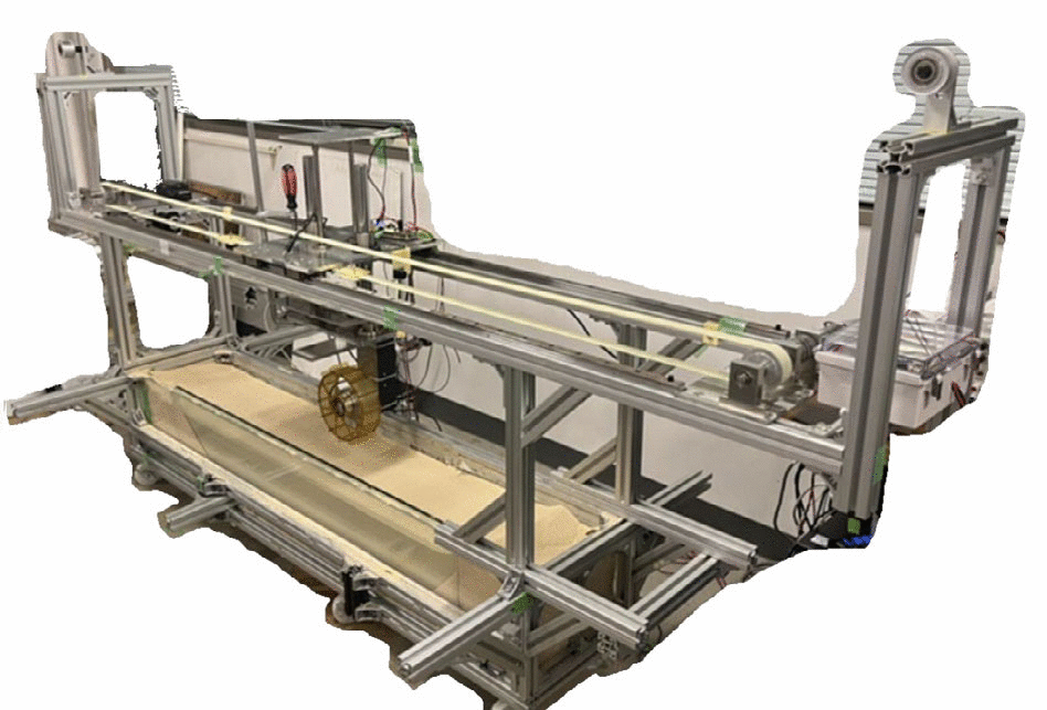
Source: [1]. CC BY 4.0.
The Space Robotics Lab in the Department of Aerospace Engineering at Tohoku University, Sendai, works on the mechanics, dynamics and control of spacecraft and of planetary exploration robots, and is closely involved in JAXA missions [6]. Its ground facilities are bench-scale terramechanics rigs rather than a large yard: a slip-controlled single wheel testbed used for wheel and grouser characterization, a modular sinkage bench for legged robot end effectors with adjustable load and ground angle [2], and rover platforms taken to external analogue sites for full-vehicle work [3]. The lab’s soils are Toyoura sand, Tohoku Silica No. 5 and FJS-1 lunar simulant [1][3].
Laboratory data
Section titled “Laboratory data”| Parameter | Value |
|---|---|
| Operator | Tohoku University, Space Robotics Laboratory, Department of Aerospace Engineering [1][6] |
| Location | Aoba Aramaki, Sendai, Japan [6] |
| Commissioned | Not published. The single wheel testbed appears in campaigns from 2019 |
| Type | Bench-scale terramechanics rigs: a slip-controlled wheel bed and a tilting sinkage bench [1][2] |
| Floor area | Not published |
| Capabilities | Wheel testbed, sinkage bench, rovers |
| Simulant or terrain | Toyoura sand, FJS-1 lunar simulant, Tohoku Silica No. 5 [1][3]. Tonnages not published |
| Instrumentation | Force sensors, encoders, hand vane, wheel trace imaging [1][2] |
| Ground truth | Hand vane bulk density before every run; angle of repose by fixed funnel [1] |
| Fidelity limits | 1 g; minimum wheel load 5 to 10 N against a 4.1 N lunar target. See below |
| Access | Not published. Laboratory research equipment, no external user route in the literature |
| Cited by | rashid |
Capabilities
Section titled “Capabilities”Single wheel testbed
Section titled “Single wheel testbed”| Parameter | Value |
|---|---|
| Working volume | Bed near 1.6 x 0.30 x 0.20 m; stable experimental region 0.4 m long |
| Test article limits | Minimum vertical load 5 to 10 N. Wheels run to date 200 mm diameter, 80 mm wide |
| Vacuum | Not applicable |
| Temperature | Not applicable |
| Illumination | Not published. Ordinary laboratory lighting |
| Simulant or terrain | Toyoura sand at 1440 kg/m3; FJS-1 at 1740 kg/m3, both 24.5 percent relative density |
| Gravity offload | Not applicable. Reduced gravity is reached by load scaling and simulation |
| Instrumentation | Force sensors, encoders, wheel trace imaging, hand vane |
Source: [1].
The testbed sets the rotational and translational velocity of the wheel independently, so that a fixed slip ratio characterizes the traveling state through the run [1]. The procedure is fixed: the soil surface is tilled to loosen it, levelled with a flat plate to a consistent horizontal height, checked for bulk density with a hand vane, then the rotational and translational velocities are set for the desired slip ratio and constant motion begins. Force sensors and encoders record force, horizontal and vertical displacement, and wheel trace images are taken. The bed is then reset and each condition repeated three times, with the experimental error taken as the standard deviation of the three run averages.
The bed dimensions are inferred rather than stated. The group publishes that its discrete element replication of 0.65 x 0.14 x 0.12 m is 40 percent of the length, 47 percent of the width and 60 percent of the depth of the real bed, which puts the physical bed near 1.6 m long, 0.30 m wide and 0.20 m deep [1]. Vertical load is commanded with the wheel’s own mass accounted for.
Modular sinkage bench
Section titled “Modular sinkage bench”| Parameter | Value |
|---|---|
| Working volume | Sand box 446 x 332 x 218 mm, filled to 100 mm depth |
| Test article limits | Manually actuated linear turret, force meter resolution 0.01 N; 66 N in the published campaign |
| Simulant or terrain | Silica sand |
| Slope | Box -45 to +45 degrees; load angle 0 to 90 degrees, set to 0.1 degree |
| Instrumentation | Force meter at 0.1 s; turret displacement to 0.01 mm; universal joint wrist |
Source: [2].
A related climbing mechanism under development at the lab replaces the sinkage bench’s gripper with an 8-fingered wheel-gripper that retracts into a cylindrical wheel for driving and extends its fingers as a micro-spine gripper for steep or uneven ground, driven by a single actuator through a tether and pulley; on a 3D-printed rough-surface analog it held 40 N in the normal direction but, unlike a dedicated comparison spine gripper, produced no holding force at all when the surface was flat under the gripper’s tested orientation [14].
The sinkage bench is built for end effectors rather than wheels. A manually actuated linear turret carries a force meter connected rigidly to the gripper; the turret sits on a curved rail so the load angle can be dialled between 0 and 90 degrees, and the sand box below is mounted on an inclination-adjustable frame covering -45 to +45 degrees, so that load direction and ground slope are set independently [2]. The wrist is a universal joint with roll and yaw freedom so that load acts through the gripper center at any inclination. Load is set to the case of a hexapod standing on three legs.
Rover platforms
Section titled “Rover platforms”The lab’s rover platforms are exercised outside these benches, at external analogue sites. EX1, a four-wheeled 21.63 kg rover of 0.82 by 0.52 by 0.67 m with a passive spring-damper suspension developed at the lab, was run at the JAXA Space Exploration Field, over a 20 m by 20 m area of Tohoku Silica No. 5 about 0.3 m deep, at wheel velocities of 0.23 to 1.17 m/s on flat ground and 0 to 18 degree slopes at up to 0.47 m/s, plus rapid acceleration and deceleration runs for transient slip [3]. The suspension concept behind EX1 was first evaluated in simulation under a 1.625 m/s2 lunar gravity field against 1 to 12 cm steps, a 10 cm hemispherical rock, a 1.5 m outcrop and 1.5 m slopes from 5 to 30 degrees, at 0.05 to 1 m/s [5].
An earlier generation of rover platforms ran on the same pattern of bench plus external sand field. The four-wheel-drive, four-wheel-steer El Dorado rover, 2 to 30 cm/s, was driven on a sandy beach for a vision-based slip angle estimator that reads the wheel’s own trace with a rear-facing camera, reaching under 2 degrees RMS error against laser ground truth on a 7 m traverse [9]. A related four-wheel-steer test vehicle, 13.5 kg, was run in an indoor sandbox of 2.0 by 1.0 m filled to 8 cm with Toyoura sand tilted to 5 and 10 degrees, comparing a model-based feed-forward steering law against sensor-based slip feedback, the feedback cutting lateral path error from 0.051 m to 0.011 m [8]. The El-Dorado II rover climbed a 12 degree Toyoura sand slope under an energy-optimal, equal-slip-ratio control law developed from the lab’s single wheel testbed data, though the reported minimum effective motor work differed by a factor of 2.6 between that experiment and the accompanying simulation [13]. A still earlier six-wheeled testbed, 5.8 kg on 90 mm wheels, established the lab’s basic method of pairing a Bekker-Wong wheel-soil model with multibody dynamics: it drove on dry sand up an increasing slope until slip went to 1 at about 12 degrees and the wheels dug in, a failure mode used since as a benchmark case rather than a general limit, since it is a property of that vehicle and that sand [7].
High-speed single wheel testbed
Section titled “High-speed single wheel testbed”A second, larger single wheel rig, purpose-built and separate from the bench above, drives wheels at translational speeds up to 1.0 m/s over a 6.85 m bed of Tohoku Silica Sand No. 5, roughly a hundred times the speed of a flown planetary rover [15]. At that speed a slick wheel needs a slip ratio of 0.25 before drawbar pull turns positive, against about 0.1 at 0.2 m/s, and its traction coefficient falls to about 0.02, a tenth of what grousers reach at low speed; a companion discrete element simulation reproduces the ordering between wheel designs but not this speed dependence, predicting traction rising with speed where the bench shows it falling [15]. The same rig, run at slower, quasi-static speeds of 0.02 to 0.04 m/s, has also compared a 200 mm Rashid-rover-pattern grouser wheel in Toyoura sand against FJS-1 lunar simulant across 0 to 50 percent slip and 5 to 70 N vertical load [16], and been scanned with a LiDAR profiler to fit ruts left at fixed 20 percent slip and three vertical loads with an inclined sine function, though several of the resulting height differences sit within the profiler’s own 3.2 mm measurement noise [17]. A parallel resistive-force-theory model of grouser geometry, validated against single-wheel tests in the same Tohoku silica sand and against discrete element simulation, chose the tilted octagonal grouser flown on JAXA’s LEV-1 lunar hopping rover; the wheel then operated on the Moon after the January 2024 SLIM landing, though the ground and simulation numbers have no flight telemetry to check against [18].
Instrumentation
Section titled “Instrumentation”Soil characterization is treated as a measurement in its own right. Particle density is measured to JIS A 1109:2020 and minimum and maximum bulk density to JIS A 1224:2020, and the static angle of repose is measured by the fixed funnel method over repeated runs, giving 34.3 degrees averaged over Toyoura runs and 38.0 degrees over seven FJS-1 runs, with the error taken as the standard deviation between the left and right side angles of each run [1]. The angle of repose is then used as the calibration target for discrete element parameters, so that a soil property measured independently of the wheel constrains the simulation the wheel results are compared against. Terrain deformation left by the wheel is used as a measurement rather than a by-product: grouser pitch is read from top-down images of the trace by measuring across several pitches and dividing, and the lab’s terrain deformation model takes vertical load and wheel pose to update a height map, with the load to depth relation obtained from discrete element single wheel runs [4].
What it does not reproduce
Section titled “What it does not reproduce”Gravity is not reduced anywhere in the published setups. The lab’s route to lunar performance is a discrete element model calibrated against Earth-gravity bench data and then run at 1.62 m/s2, and the comparison it produces is a prediction, not a measurement: 4.1 N under lunar gravity matched the 24.5 N Earth gravity results for traction coefficient and tractive efficiency, with a 1 to 2 mm difference in total sinkage, and tractive force and resistive torque both reduced by a factor of six [1]. The load floor blocks the direct experiment that would test that prediction: the bench could not go below about 5 to 10 N, so the 4.1 N lunar-equivalent load could not be applied on Earth.
Soil reproduction is bounded on both sides. FJS-1’s measured bulk density range could not be covered in the matched simulation without raising particle density above the measured value, so the higher packing densities were not studied [1]. In the field, the sand used is not a mineralogical simulant at all: Tohoku Silica No. 5 is dry loose silica sand described as a low-fidelity lunar regolith simulant whose sparse grain distribution presents harsher sinkage and slip conditions than the real material [3].
Scale bounds the wheel runs. The stable region of the bed is 0.4 m long, which sets how much steady-state travel is available after transients, and at the higher speeds the group is interested in, above about 0.1 m/s, transient effects occupy a growing fraction of that distance [1]. The discrete element replication is smaller still, 0.65 m by 0.14 m by 0.12 m, sized so that boundary interaction does not impede soil flow rather than to match the bed, and its particles are represented at 1 mm radius against the sub-millimeter real grain size, a scaling of more than ten times that the authors identify as common practice and a known source of error [4].
Where the Tohoku rigs sit among other terramechanics facilities
Section titled “Where the Tohoku rigs sit among other terramechanics facilities”The lab’s benches follow a lineage that starts with Apollo-era wheel testing. Boeing and General Motors single-wheel dynamometer tests of the flight lunar roving vehicle wheel in a moistened simulant found pull coefficient insensitive to wheel speed and to loads of 178 to 377 N, with soil strength the controlling variable, and all of it was measured at 1 g in air [28]. The comparison of five candidate lunar wheels in fine sand reached the same limit on medium: moisture imposed cohesion, so the result that added cohesion did not help cannot be carried to dry lunar regolith [29]. Tohoku’s rigs inherit both limits, since they too run at 1 g in air in dry sand.
Other single-wheel facilities differ mainly in how much of the test cycle is automated. DLR’s TROLL places a force-controlled industrial robot over a 3 m traverse with a wheel load up to 1 kN and speeds above 1 m/s, and automates tillage, leveling and compaction so that preparation and test run as one sequence [25]. A demonstration of 115 side-slip tests was run by one person in three days, work the author says would take weeks on a manual rig [24]. A semi-automated rail-guided plow and sled for a worst-case soft simulant cut bulk density scatter in compaction from 0.023 to 0.005 g/cm3 against a manual board walk [26]. The Tohoku bed is prepared by hand (tilling, plate leveling, hand vane check) [1], so its repeatability rests on procedure and on three repeats per condition rather than on automation, and the literature gives no preparation scatter figure for it. DLR’s earlier Oberpfaffenhofen soil bin, 5.5 by 10 by 0.5 m with camera-based elevation mapping and a purpose-built bevameter, is the larger-scale counterpart of the Tohoku sinkage bench, and its Bekker fit returned a negative cohesive modulus that the authors attributed to a two-layer bed [23].
Soil fidelity is the other axis. Standardized ASTM testing of six lunar simulants found that matching the lunar average particle size distribution does not fix shear strength or compressibility [27], which bears on the Toyoura sand and FJS-1 choice in Tohoku’s runs. Grouser behavior has been studied on the same single-wheel pattern at NASA, where grouser gain on GRC-1 was attributed to removed compaction resistance rather than added thrust, a theory the authors did not test directly [22]. Discrete element wheel work at JAXA’s sloped bed with FJS-1 selected an 18-lug, 250 mm rim wheel for a SELENE-2 micro rover, and rerunning the model at one sixth gravity showed reduced gravity weakens performance in simulation, which no ground rig confirmed [21]. NASA’s constant lunar soil parameters for rover simulation are quoted from the literature without uncertainty or per-value sources [30].
Reduced gravity: what is measured and what is modeled
Section titled “Reduced gravity: what is measured and what is modeled”The Tohoku group does not reduce gravity on any rig in the published record. Parabolic flights on a Falcon 20 are the experimental route that does: single-wheel runs there showed that matching only wheel load overstates lunar mobility, with drawbar pull to weight down 20 percent or more and sinkage up to 40 percent at equal load, and the equal cone index gradient assumption behind GRC-1 overstated it further [19]. Each parabola gives 20 to 30 s, so every run is a transient [19]. A physics-based GPU simulation reached the same direction of conclusion: mass reduction leaves the soil at Earth strength and so gives overoptimistic trafficability, but the lunar results are model output validated only on 1 g data [20]. Drop-tower shear cells, with a 1.8 m reduced gravity tower variant, measure regolith strength at low acceleration; the published paper reports an instrument and no reduced gravity strength results [31]. Tohoku’s lunar traction numbers sit in the same category as [20]: calibrated simulation, extrapolated to 4.1 N, with the Hurrell result that traction coefficient is unchanged from 1 g at full load [1] remaining an untested prediction, and the parabolic-flight data above showing that load-matched tests at 1 g can be wrong in the optimistic direction [19].
Manipulator and free-flying testbeds
Section titled “Manipulator and free-flying testbeds”Before the lab’s terramechanics work, its ground facilities centered on manipulator control and free-flying capture, and those testbeds still frame how it verifies control laws before trusting simulation. TREP, a two-joint arm mounted on a deliberately flexible double beam, was used to show that a reaction null-space control law lets the arm track a path without exciting the base while a separate loop damps whatever vibration the base already has, tested at two very different traverse speeds against a point-to-point move that vibrated the base strongly by comparison; the beam was designed so that reaction torque and one reaction force component could be neglected, which simplifies the problem relative to a real spacecraft [10]. An air-floating table gives the lab’s free-flying capture work its planar microgravity: a compliant-wrist impedance controller aimed at a zero coefficient of restitution on contact with a non-cooperative target reached 0.016 +/- 0.011 in practice, with the gap attributed to wrist friction and sensor noise rather than the contact model [11], and a later dual-arm study on the same class of rig showed repeated deliberate impacts, rather than a single grapple, damping a spinning target’s angular velocity to a steady low-velocity state within about six seconds [12]. Both are two-dimensional rigs and neither reproduces the three-dimensional tumbling or out-of-plane torques a real capture would see.
Campaigns run there
Section titled “Campaigns run there”Rashid-1 wheel traction evaluation. A wheel modeled on the Emirates Lunar Mission Rashid-1 rover, 100 mm radius, 80 mm wide, 14 grousers of 20 mm and 1.18 kg, was run in Toyoura sand and FJS-1 at the nominal per-wheel load of 24.5 N for a 10 kg rover, at 0.02 m/s nominal horizontal speed and 0.2 rad/s at zero slip, over slip ratios from 10 to 50 percent [1]. Traction coefficient and dynamic sinkage agreed between experiment and discrete element simulation over the 0 to 50 percent slip range in both soils. Grouser pitch in the wheel trace was found to be unchanged by gravity variation, which makes it usable as a visual slip indicator [1]. The wheel used on the bench differs from the flight wheel in grouser length, mass and material, with vertical load adjustment used to hold the correct load despite the mass difference. See rashid.
Legged robot gripper sinkage, 2024. An underactuated tendon-driven microspine gripper for the SCAR-E hexapod was pressed into silica sand at slope angles from 0 to 35 degrees under a load representing the robot standing on three legs [2]. Maximum sinkage rose from 12.98 mm at 0 degrees to 36.19 mm at 35 degrees, with the increase accelerating beyond 25 degrees; the operators attribute the steep rise at 35 degrees to granular collapse at the slope surface, and report agreement with the coupled multibody and discrete element model to within about 10 percent at 66 N [2].
Wheel trace deformation model, 2024. Discrete element single wheel runs were used to derive a load to depth relation for a 200 mm diameter, 80 mm wide wheel with 14 grousers of 20 mm, in a virtual bed of 0.65 m by 0.14 m by 0.12 m of Toyoura sand represented at 1 mm particle radius, and the resulting trace amplitude and profile were fed into a real-time height-map deformation model driven by vertical load and wheel pose [4].
Data-driven simulator calibration, 2026. Slip and sinkage regressions derived from the single wheel testbed, from discrete element simulation and from the EX1 field campaign were combined and integrated into the OmniLRS lunar surface simulator, targeting flat terrain and slopes to 20 degrees [3]. The group notes that including grouser length in the effective wheel radius is necessary for the slip ratio to come out positive during acceleration and steady-state driving, and negative during deceleration, as it should [3].
References
Section titled “References”References
- Hurrell, J., Takehana, K., Tanaka, T., Uno, K., Busoud, A. K. and Yoshida, K. (2025). Traction Performance Evaluation for a Rashid-1 Rover Wheel
. Space Science Reviews, 3. Source
BibTeX
@article{hurrell2025traction, title = {Traction Performance Evaluation for a Rashid-1 Rover Wheel}, author = {Hurrell, James and Takehana, Keisuke and Tanaka, Tomomi and Uno, Kentaro and Busoud, Amna Khalifa and Yoshida, Kazuya}, journal = {Space Science Reviews}, volume = {221}, number = {3}, pages = {37}, year = {2025}, doi = {10.1007/s11214-025-01164-8}, abstract = {Abstract Single-wheel experiments and discrete element method simulations of a micro-rover wheel modelled on the Rashid-1 rover designed for the Emirates lunar mission. The interaction of the wheel with Toyoura sand and FJS-1 lunar regolith simulant is studied. Slip conditions, traction coefficient and grouser pitch for single-wheel experiments are measured for a range of fixed slip values at the expected rover load of 24.5 N. The angle of repose is used to calibrate the simulation parameters with measured soil parameters. Single-wheel simulations are verified by comparison to experimental results. Lunar simulations can predict lunar gravity performance. Toyoura and FJS-1 results for traction coefficient and dynamic sinkage at 24.5 N in the 0–50% slip range show good agreement between experiment and simulation. 4.1 N lunar gravity matches the 24.5 N Earth gravity results for traction coefficient and tractive efficiency. There is a 1–2 mm difference in total sinkage. Tractive force and resistive torque reduce by 1/6 from Earth to lunar gravity for the same mass. The grouser pitch is unchanged with gravity variation. The angle of repose can independently determine parameters for use in single-wheel simulations. Experimental results validate the models for Toyoura sand and FJS-1. Wheel performance regarding traction coefficient and tractive efficiency under lunar gravity matches that under Earth gravity. Traction performance in tractive force and resistive torque is reduced by the ratio of Earth to lunar gravity, 1/6, for the same mass.} } - Candalot, A., Hurrell, J., Hashim, M.-M., Hickey, B., Laine, M. and Yoshida, K. (2024). Sinkage Study in Granular Material for Space Exploration Legged Robot Gripper
. International and Asia-Pacific Regional Conference of the International Society for Terrain-Vehicle Systems. Source
BibTeX
@inproceedings{candalot2024sinkage, title = {Sinkage Study in Granular Material for Space Exploration Legged Robot Gripper}, author = {Candalot, Arthur and Hurrell, James and Hashim, Malik-Manel and Hickey, Brigid and Laine, Mickael and Yoshida, Kazuya}, booktitle = {International and Asia-Pacific Regional Conference of the International Society for Terrain-Vehicle Systems}, address = {Yokohama}, year = {2024}, doi = {10.56884/fluruda3} } - Kern, J. M., Hurrell, J. M., Santra, S., Takehana, K., Uno, K. and Yoshida, K. (2025). Data-Driven Terramechanics Approach Towards a Realistic Real-Time Simulator for Lunar Rovers
. arXiv preprint. Source
BibTeX
@article{kern2026data, title = {Data-Driven Terramechanics Approach Towards a Realistic Real-Time Simulator for Lunar Rovers}, author = {Kern, Jakob M. and Hurrell, James M. and Santra, Shreya and Takehana, Keisuke and Uno, Kentaro and Yoshida, Kazuya}, journal = {arXiv preprint}, pages = {662-668}, year = {2025}, doi = {10.1109/isparo66239.2025.11436587}, abstract = {High-fidelity simulators for the lunar surface provide a digital environment for extensive testing of rover operations and mission planning. However, current simulators focus on either visual realism or physical accuracy, which limits their capability to replicate lunar conditions comprehensively. This work addresses that gap by combining high visual fidelity with realistic terrain interaction for a realistic representation of rovers on the lunar surface. Because direct simulation of wheel-soil interactions is computationally expensive, a data-driven approach was adopted, using regression models for slip and sinkage from data collected in both full-rover and single-wheel experiments and simulations. The resulting regression-based terramechanics model accurately reproduced steady-state and dynamic slip, as well as sinkage behavior, on flat terrain and slopes up to 20°, with validation against field test results. Additionally, improvements were made to enhance the realism of terrain deformation and wheel trace visualization. This method supports real-time applications that require physically plausible terrain response alongside high visual fidelity.} } - Kamohara, J., Ares, V., Hurrell, J., Takehana, K., Richard, A., Santra, S., Uno, K., Rohmer, E. and Yoshida, K. (2024). Modeling of Terrain Deformation by a Grouser Wheel for Lunar Rover Simulation
. arXiv preprint. Source
BibTeX
@article{kamohara2024modeling, title = {Modeling of Terrain Deformation by a Grouser Wheel for Lunar Rover Simulation}, author = {Kamohara, Junnosuke and Ares, Vinicius and Hurrell, James and Takehana, Keisuke and Richard, Antoine and Santra, Shreya and Uno, Kentaro and Rohmer, Eric and Yoshida, Kazuya}, journal = {arXiv preprint}, year = {2024}, doi = {10.56884/fryx2uhe} } - Rodríguez-Martínez, D., Uno, K., Sawa, K., Uda, M., Kudo, G., Diaz, G. H., Umemura, A., Santra, S. and Yoshida, K. (2023). Enabling Faster Locomotion of Planetary Rovers with a Mechanically-Hybrid Suspension
. IEEE Robotics and Automation Letters. Source
BibTeX
@article{rodriguezmartinez2023enabling, title = {Enabling Faster Locomotion of Planetary Rovers with a Mechanically-Hybrid Suspension}, author = {Rodríguez-Martínez, David and Uno, Kentaro and Sawa, Kenta and Uda, Masahiro and Kudo, Gen and Diaz, Gustavo Hernan and Umemura, Ayumi and Santra, Shreya and Yoshida, Kazuya}, journal = {IEEE Robotics and Automation Letters}, year = {2023}, doi = {10.48550/arxiv.2307.04494}, abstract = {The exploration of the lunar poles and the collection of samples from the martian surface are characterized by shorter time windows demanding increased autonomy and speeds. Autonomous mobile robots must intrinsically cope with a wider range of disturbances. Faster off-road navigation has been explored for terrestrial applications but the combined effects of increased speeds and reduced gravity fields are yet to be fully studied. In this paper, we design and demonstrate a novel fully passive suspension design for wheeled planetary robots, which couples for the first time a high-range passive rocker with elastic in-wheel coil-over shock absorbers. The design was initially conceived and verified in a reduced-gravity (1.625 m/s${^2}$) simulated environment, where three different passive suspension configurations were evaluated against steep slopes and unexpected obstacles, and later prototyped and validated in a series of field tests. The proposed mechanically-hybrid suspension proves to mitigate more effectively the negative effects (high-frequency/high-amplitude vibrations and impact loads) of faster locomotion (~1\,m/s) over unstructured terrains under varied gravity fields.} } - (2026). Space Robotics Lab: About. astro2.mech.tohoku.ac.jp/en/about
BibTeX
@misc{tohokusrlabout, title = {Space Robotics Lab: About}, organization = {astro2.mech.tohoku.ac.jp}, year = {2026}, url = {https://astro2.mech.tohoku.ac.jp/en/about/} } - Yoshida, K. and Hamano, H. (2002). Motion Dynamics of a Rover with Slip-Based Traction Model
. International Conference on Robotics and Automation. Source
BibTeX
@inproceedings{yoshida2002motion, title = {Motion Dynamics of a Rover with Slip-Based Traction Model}, author = {Yoshida, Kazuya and Hamano, Hiroshi}, booktitle = {International Conference on Robotics and Automation}, volume = {3}, pages = {3155--3160}, address = {Washington, Washington}, year = {2002}, doi = {10.1109/robot.2002.1013712}, abstract = {This paper investigates kinetic behavior of a planetary rover with attention to tire-soil traction mechanics and articulated body dynamics, and thereby study the control when the rover travels over natural rough terrain. Experiments are carried out with a rover test bed to observe the physical phenomena of soils and to model the traction mechanics, using the tire slip ratio as a state variable. The relationship of load-traction factor versus the slip ratio is modeled theoretically then verified by experiments, as well as specific parameters to characterize the soil are identified. A dynamic simulation model is developed considering the characteristics of wheel actuators, the mechanics of tire-soil traction, and the articulated body dynamics of a suspension mechanism. Simulations are carried out to be compared with the corresponding experimental data and verified to represent the physical behavior of a rover.} } - Ishigami, G., Nagatani, K. and Yoshida, K. (2009). Slope traversal controls for planetary exploration rover on sandy terrain
. Journal of Field Robotics, 3. Source
BibTeX
@article{ishigami2009slope, title = {Slope traversal controls for planetary exploration rover on sandy terrain}, author = {Ishigami, Genya and Nagatani, Keiji and Yoshida, Kazuya}, journal = {Journal of Field Robotics}, volume = {26}, number = {3}, pages = {264--286}, year = {2009}, doi = {10.1002/rob.20277}, abstract = {Abstract In this paper, two control approaches are presented for exploration rovers traversing sandy‐sloped terrain. One of the proposed controls is a model‐based feed‐forward control using a characteristic diagram, called a thrust‐cornering characteristic diagram . It consists of various characteristic curves of wheel forces for varied wheel slip conditions. An appropriate steering maneuver for slope traversal can be found using the diagram with slope traversal criteria. The other control is a sensor‐based feedback control. A key approach to this feedback control is to compensate for three types of slip, namely, the vehicle sideslip and longitudinal/lateral slips of a wheel. The feedback control calculates both steering and driving maneuvers that can compensate for these slips and also allow the rover to successfully traverse a sandy slope. The performances of these two control approaches are confirmed in slope traversal experiments using a four‐wheeled rover test bed. The proposed controls are verified by quantitative evaluations of distance and orientation errors. Through the experiment, it was found that the two controls have advantages and disadvantages, and the possibility of merging the model‐based control and the sensor‐based control is discussed. © 2009 Wiley Periodicals, Inc.} } - Reina, G., Ishigami, G., Nagatani, K. and Yoshida, K. (2008). Vision-Based Estimation of Slip Angle for Mobile Robots and Planetary Rovers
. IEEE International Conference on Robotics and Automation. Source
BibTeX
@inproceedings{reina2008vision, title = {Vision-Based Estimation of Slip Angle for Mobile Robots and Planetary Rovers}, author = {Reina, Giulio and Ishigami, Genya and Nagatani, Keiji and Yoshida, Kazuya}, booktitle = {IEEE International Conference on Robotics and Automation}, volume = {2008}, pages = {486-491}, publisher = {IEEE}, year = {2008}, doi = {10.1109/robot.2008.4543254}, abstract = {For a mobile robot it is critical to detect and compensate for slippage, especially when driving in rough terrain environments. Due to its highly unpredictable nature, drift largely affects the accuracy of localization and control systems, even leading, in extreme cases, to the danger of vehicle entrapment with consequent mission failure. This paper presents a novel method for lateral slip estimation based on visually observing the trace produced by the wheels of the robot, during traverse of soft, deformable terrain, as that expected for lunar and planetary rovers. The proposed algorithm uses a robust Hough transform enhanced by fuzzy reasoning to estimate the angle of inclination of the wheel trace with respect to the vehicle reference frame. Any deviation of the wheel trace from the planned path of the robot suggests occurrence of sideslip that can be detected, and more interestingly, measured. This allows one to estimate the actual heading angle of the robot, usually referred to as the slip angle. The details of the various steps of the visual algorithm are presented and the results of experimental tests performed in the field with an all-terrain rover are shown, proving the method to be effective and robust.} } - Nenchev, D. N., Yoshida, K., Vichitkulsawat, P. and Uchiyama, M. (1999). Reaction Null-Space Control of Flexible Structure Mounted Manipulator Systems
. IEEE Transactions on Robotics and Automation, 6. Source
BibTeX
@article{nenchev1999reaction, title = {Reaction Null-Space Control of Flexible Structure Mounted Manipulator Systems}, author = {Nenchev, Dragomir N. and Yoshida, Kazuya and Vichitkulsawat, P. and Uchiyama, Masaru}, journal = {IEEE Transactions on Robotics and Automation}, volume = {15}, number = {6}, pages = {1011--1023}, year = {1999}, doi = {10.1109/70.817666}, abstract = {A composite control law for end-effector path tracking with a flexible structure mounted manipulator system is proposed, such that no disturbances on the flexible base are induced. The control law is based on the reaction null-space concept introduced earlier to tackle dynamic interaction problems of free-floating robots, or moving base robots in general. The control law is called composite since it ensures base vibration suppression control as well, although independently of the reactionless motion control subtask. The requirement of task independence is essential to avoid the appearance of complex dynamics expressions in the control law, such as nonlinear velocity-dependent coupling terms and dependencies of inertias on the elastic coordinates. We present experimental data from computer simulations and the experimental test bed TREP developed at Tohoku university. The experimental data is shown to agree well with theory.} } - Uyama, N., Nakanishi, H., Nagaoka, K. and Yoshida, K. (2012). Impedance-based contact control of a free-flying space robot with a compliant wrist for non-cooperative satellite capture
. IEEE/RSJ International Conference on Intelligent Robots and Systems. Source
BibTeX
@inproceedings{uyama2012impedance, title = {Impedance-based contact control of a free-flying space robot with a compliant wrist for non-cooperative satellite capture}, author = {Uyama, Naohiro and Nakanishi, Hiroki and Nagaoka, Kenji and Yoshida, Kazuya}, booktitle = {IEEE/RSJ International Conference on Intelligent Robots and Systems}, pages = {4477-4482}, publisher = {IEEE}, year = {2012}, doi = {10.1109/iros.2012.6386082}, abstract = {This paper presents the impedance-based contact control of a free-flying space robot utilizing a compliant wrist for non-cooperative satellite capture operation. An open loop impedance control law based on contact dynamics model is introduced to realize a desired coefficient of restitution defined between a manipulator hand of a space robot and a contact point on a free-flying target. The coefficient of restitution and the damping ratio are expressed as a function of contact and impedance parameters; and hence, the impedance parameters are tuned by setting a desired coefficient of restitution and a desired damping ratio. The collision experiment using twodimensional microgravity emulator, called air-floating test bed, verifies that the proposed open loop control law is capable of realizing a desired coefficient of restitution with fairly small errors.} } - Nagaoka, K., Kameoka, R. and Yoshida, K. (2018). Repeated Impact-Based Capture of a Spinning Object by a Dual-Arm Space Robot
. Journal of Robotics and Mechatronics. Source
BibTeX
@article{nagaoka2018repeated, title = {Repeated Impact-Based Capture of a Spinning Object by a Dual-Arm Space Robot}, author = {Nagaoka, Kenji and Kameoka, Ryota and Yoshida, Kazuya}, journal = {Journal of Robotics and Mechatronics}, volume = {5}, pages = {115--115}, publisher = {Frontiers Media SA}, year = {2018}, doi = {10.3389/frobt.2018.00115}, abstract = {This paper presents detumbling and capture of space debris by a dual-arm space robot for active space debris removal missions. Space debris, such as a malfunctioning satellite or a rocket upper stage, often has uncontrolled tumbling motion. It also has uncertainties in its parameters, such as inertial characteristics or surface frictional roughness. These factors make the debris capture missions difficult to accomplish. To cope with such challenging missions, we propose a detumbling and capture control method for a dual-arm robot based on repeated impact capable of suppressing the debris motion by repeatedly utilizing an effect of a passive damping factor in the contact characteristics. In this paper, as the initial step of a study on the repeated impact-based capture method, we assume that the capture target is a rocket upper stage that can be simply modeled as a cylindrical body and mainly has angular velocity motion in its principle axis of inertia. A motion tracking control law of an end-effector of the robot arm is introduced to maintain the repeated impact. The proposed control method enables the robot to accomplish the detumbling and capture without precise estimation of the inertial characteristics and surface frictional roughness of the debris. The validity of the proposed method is presented by numerical simulations and planar microgravity experiments using an air-floating system. In particular, the experimental evaluation shows the fundamental feasibility of the proposed method, and thus, the result contributes to a practical application.} } - Ding, L., Gao, H., Deng, Z. and Liu, Z. (2010). Slip-ratio-coordinated control of planetary exploration robots traversing over deformable rough terrain
. IEEE/RSJ International Conference on Intelligent Robots and Systems. Source
BibTeX
@inproceedings{ding2010slip, title = {Slip-ratio-coordinated control of planetary exploration robots traversing over deformable rough terrain}, author = {Ding, Liang and Gao, Haibo and Deng, Zongquan and Liu, Zhen}, booktitle = {IEEE/RSJ International Conference on Intelligent Robots and Systems}, pages = {4958-4963}, publisher = {IEEE}, year = {2010}, doi = {10.1109/iros.2010.5652250} } - Uda, M., Sawa, K., Uno, K., Kato, T., Lim, L. B. and Yoshida, K. (2024). Development and Grasping Performance Evaluation of a Wheel-Gripper Transformable Mechanism
. Journal of the Robotics Society of Japan. Source
BibTeX
@article{uda2024development, title = {Development and Grasping Performance Evaluation of a Wheel-Gripper Transformable Mechanism}, author = {Uda, M. and Sawa, K. and Uno, Kentaro and Kato, Takuya and Lim, Luina Benevides and Yoshida, Kazuya}, journal = {Journal of the Robotics Society of Japan}, volume = {42}, pages = {580-583}, publisher = {The Robotics Society of Japan}, year = {2024}, doi = {10.7210/jrsj.42.580}, abstract = {Extreme environments like lunar and planetary surfaces, disaster sites, and volcanoes have severely uneven terrain and steep slopes. Conventional robots currently lack mechanisms for negotiating such terrain. In this paper, we developed a mechanism that can potentially serve as either a gripper or a wheel - via retractable fingers. When the fingers are retracted, they form a cylindrical shape that acts as a wheel. When the fingers are extended, they act as a gripper. The fingers are controlled by a single actuator. We conducted a grasping force experiment and confirmed that the mechanism could exert the same holding force as an existing gripper.} } - Takehana, R., Kenny, S., Sawa, K., Hurrell, C., Uno, K., Santra, N. and Yoshida, K. (2025). Grouser Wheel High-Speed Traction Performance: DEM Simulation and Experimental Result
. Journal of Terramechanics. Source
BibTeX
@article{takehana2025grouser, title = {Grouser Wheel High-Speed Traction Performance: {DEM} Simulation and Experimental Result}, author = {Takehana, Ryosuke and Kenny, Sean and Sawa, Kento and Hurrell, Callum and Uno, Kentaro and Santra, Nishant and Yoshida, Kazuya}, journal = {Journal of Terramechanics}, volume = {120}, pages = {101084}, year = {2025}, doi = {10.1016/j.jterra.2025.101084}, abstract = {This study focuses on the locomotion characteristics of a high-speed lunar exploration rover. We conduct single-wheel tests under high-speed conditions and provide detailed results from force measurements from both approaches (experiment and simulation). Three types of wheels are prepared: no grouser, low grouser, and high grouser, and their traction performance is compared. The testbed allows speeds of 1 m/s, which is about a hundred times faster than conventional exploration speeds. We also have developed a Discrete Element Method (DEM) simulator to reproduce the same behavior of the experimental testbed. We calculated traction coefficient and traction efficiency for variable slip ratios, and these are evaluated as traction performance. Both results of the experiment and simulation revealed a trend where traction performance decreases as driving velocity increases. Each performance exhibited substantial dependence on not only the slip ratio but also the magnitude of the wheel circumference velocity. Additionally, we confirmed the effectiveness of grouser wheels even at high speeds by evaluating different height of wheels. Finally, A detailed comparison of the experimental results and simulations suggested that more accurate matching could be achieved by optimizing the contact parameters between the wheel and the particles.} } - Takehana, K., Kizaki, S., Tanaka, T., Uno, K. and Yoshida, K. (2025). Comparison of lunar rover wheel performance in soils with different cohesive properties
. Icarus. Source
BibTeX
@article{takehana2025comparison, title = {Comparison of lunar rover wheel performance in soils with different cohesive properties}, author = {Takehana, Keisuke and Kizaki, Shino and Tanaka, Tomomi and Uno, Kentaro and Yoshida, Kazuya}, journal = {Icarus}, volume = {117}, pages = {101011}, publisher = {Elsevier BV}, year = {2025}, doi = {10.1016/j.jterra.2024.101011} } - Takehana, K., Ares, V. E., Santra, S., Uno, K., Rohmer, E. and Yoshida, K. (2025). Rutting Caused by Grouser Wheel of Planetary Rover in Single-Wheel Testbed: LiDAR Topographic Scanning and Analysis
. Aerospace, 1. Source
BibTeX
@article{takehana2025rutting, title = {Rutting Caused by Grouser Wheel of Planetary Rover in Single-Wheel Testbed: {LiDAR} Topographic Scanning and Analysis}, author = {Takehana, Keisuke and Ares, Vinicius Emanoel and Santra, Shreya and Uno, Kentaro and Rohmer, Eric and Yoshida, Kazuya}, journal = {Aerospace}, volume = {12}, number = {1}, pages = {71}, year = {2025}, doi = {10.3390/aerospace12010071}, abstract = {This paper presents datasets and analyses of 3D LiDAR scans capturing the rutting behavior of a rover wheel in a single-wheel terramechanics testbed. The data were acquired using a LiDAR sensor to record the terrain deformation caused by the wheel’s passage through a Toyoura sandbed, which mimics lunar regolith. Vertical loads of 25 N, 40 N, and 65 N were applied to study how rutting patterns change, focusing on rut amplitude, height, and inclination. This study emphasizes the extraction and processing of terrain profiles from noisy point cloud data, using methods like curve fitting and moving averages to capture the ruts’ geometric characteristics. A sine wave model, adjusted for translation, scaling, and inclination, was fitted to describe the wheel-induced wave-like patterns. It was found that the mean height of the terrain increases after the grouser wheel passes over it, forming ruts that slope downward, likely due to the transition from static to dynamic sinkage. Both the rut depth at the end of the wheel’s path and the incline increased with larger loads. These findings contribute to understanding wheel–terrain interactions and provide a reference for validating and calibrating models and simulations. The dataset from this study is made available to the scientific community.} } - Otsuki, M., Yoshikawa, K., Maeda, T., Usami, N. and Yoshimitsu, T. (2025). Design of Wheel Grouser Geometry With Reduced Sinkage for LEV-1 Lunar Rover
. IEEE Robotics and Automation Letters, 6. Source
BibTeX
@article{otsuki2025design, title = {Design of Wheel Grouser Geometry With Reduced Sinkage for LEV-1 Lunar Rover}, author = {Otsuki, Masatsugu and Yoshikawa, Kent and Maeda, Takao and Usami, Naoto and Yoshimitsu, Tetsuo}, journal = {IEEE Robotics and Automation Letters}, volume = {10}, number = {6}, pages = {5633-5640}, publisher = {Institute of Electrical and Electronics Engineers (IEEE)}, year = {2025}, doi = {10.1109/lra.2025.3561571} } - Daca, A. (2023). Predicting Planetary Rover Mobility in Reduced Gravity Using 1-g Experiments
. Unpublished. Source
BibTeX
@phdthesis{daca2023predicting, title = {Predicting Planetary Rover Mobility in Reduced Gravity Using 1-g Experiments}, author = {Daca, Adriana}, journal = {Unpublished}, school = {Concordia University}, address = {Montreal, Quebec, Canada}, type = {PhD thesis}, month = {February}, year = {2023}, doi = {10.13140/rg.2.2.12718.28485}, abstract = {Traversing granular regolith, especially in reduced gravity environments, remains a potential challenge for wheeled rovers. Mitigating hazards for planetary rovers requires testing in representative environments, but direct Earth-based testing fails to account for the effect of reduced gravity on the soil itself. Here, experimental apparatus and techniques for reduced-gravity flight testing are used to systematically evaluate three existing Earth-based testing methods and develop guidelines for their use and interpretation: (i) reduced-weight testing, (ii) matching soil testing instrument response through soil simulant design, and (iii) granular scaling laws (GSL). \nExperimentation campaigns flying reduced-gravity parabolas, with soil and wheel both in lunar-g, have shown reductions in net traction of 20% or more and increases in sinkage of up to 40% compared to Earth-based testing methods (i) and (ii). Scaled-wheel testing, according to GSL (method iii) has shown better agreement with reduced-g tests (less than 10% error) and also tends to err on the side of conservative predictions. \nLimitations of GSL are investigated including a recently proposed cohesion constraint (that the wheel radius ratio must be the inverse of the gravity ratio) and the effects of wheel size and aspect ratio on GSL’s accuracy. It was found that the cohesion constraint can most likely be ignored for mildly cohesive soils such as lunar regolith. Limits on wheel sizes and aspect ratio variation are also proposed. \nThe application of GSL to planetary rover testing is demonstrated through two studies undertaken in collaboration with NASA’s Jet Propulsion Laboratory. One study compares wheel designs for a skid-steer lunar rover in single-wheel tests scaled by GSL, demonstrating that diagonal grousers improve turning performance without requiring larger wheels. The second study involves application of GSL to the design of two reconfigurable test platforms for evaluating steep-terrain mobility performance. \nAnother aspect of rover mobility testing—normal force control in single-wheel testbeds—is also investigated. An improved method for single-wheel testing, using a 4-bar mechanism, essentially eliminates normal force oscillations from frictional vertical sliders. \nFinally, guidelines for conducting and interpreting 1-g mobility tests for lunar rovers are presented, and potential avenues for future research are outlined.} } - Hu, W., Li, P., Rogg, A., Schepelmann, A., Creager, C., Chandler, S., Kamrin, K. and Negrut, D. (2024). Using physics-based simulation towards eliminating empiricism in extraterrestrial terramechanics applications
. arXiv preprint. Source
BibTeX
@article{hu2024physics, title = {Using physics-based simulation towards eliminating empiricism in extraterrestrial terramechanics applications}, author = {Hu, Wei and Li, Pei and Rogg, Arno and Schepelmann, Alexander and Creager, Colin and Chandler, Samuel and Kamrin, Ken and Negrut, Dan}, journal = {arXiv preprint}, year = {2024}, doi = {10.13140/rg.2.2.33352.94728} } - Nakashima, H., Fujii, H., Oida, A., Momozu, M., Kanamori, H., Aoki, S., Yokoyama, T., Shimizu, H., Miyasaka, J. and Ohdoi, K. (2010). Discrete Element Method Analysis of Single Wheel Performance for a Small Lunar Rover on Sloped Terrain
. Journal of Terramechanics, 5. Source
BibTeX
@article{nakashima2010discrete, title = {Discrete Element Method Analysis of Single Wheel Performance for a Small Lunar Rover on Sloped Terrain}, author = {Nakashima, H. and Fujii, H. and Oida, A. and Momozu, M. and Kanamori, H. and Aoki, S. and Yokoyama, T. and Shimizu, H. and Miyasaka, J. and Ohdoi, K.}, journal = {Journal of Terramechanics}, volume = {47}, number = {5}, pages = {307--321}, year = {2010}, doi = {10.1016/j.jterra.2010.04.001} } - Moreland, S., Skonieczny, K., Inotsume, H. and Wettergreen, D. (2012). Soil Behavior of Wheels with Grousers for Planetary Rovers
. IEEE Aerospace Conference. Source
BibTeX
@inproceedings{moreland2012soil, title = {Soil Behavior of Wheels with Grousers for Planetary Rovers}, author = {Moreland, Scott and Skonieczny, Krzysztof and Inotsume, Hiroaki and Wettergreen, David}, booktitle = {IEEE Aerospace Conference}, pages = {1-8}, address = {Big Sky, Montana}, year = {2012}, doi = {10.1109/aero.2012.6187040}, abstract = {The performance of wheels operating in loose granular material for the application of planetary vehicles is well researched but little effort has been made to study the soil shearing which governs traction. Net traction measurements and application of energy metrics have been solely relied upon to investigate performance but lack the ability to evaluate or describe soil-wheel interaction leading to thrust and resistances. The complexity of rim and grouser interaction with the ground has also prevented adequate models from being formulated. This work relies on empirical data gathered in attempt to study the effects of rim surface on soil shearing and ultimately how this governs traction. A novel experimentation and analysis technique was developed to enable investigation of terramechanics fundamentals in great detail. This technique, the Shear Interface Imaging Analysis Tool, is utilized to provide visualization and analysis capability of soil motion at and below the wheel-soil interface. Analysis of the resulting displacement field identifies clusters of soil motion and shear interfaces. Complexities in soil flow patterns greatly affect soil structure below the wheel and the resulting tractive capability. Grouser parameter variations, spacing and height, are studied for a rigid wheel. The results of soil shear interface analysis for wheels with grousers are presented. The processes of thrust and resistances are investigated and behavior characterized for grousered wheels.} } - Apfelbeck, M., Kuß, S., Wedler, A., Gibbesch, A., Rebele, B. and Schäfer, B. (2009). A Novel Terramechanics Testbed Setup for Planetary Rover Wheel-Soil Interaction
. European Regional Conference of the International Society for Terrain-Vehicle Systems. Source
BibTeX
@inproceedings{apfelbeck2009novel, title = {A Novel Terramechanics Testbed Setup for Planetary Rover Wheel-Soil Interaction}, author = {Apfelbeck, Maximilian and Kuß, Sebastian and Wedler, Armin and Gibbesch, Andreas and Rebele, Bernhard and Schäfer, Bernd}, booktitle = {European Regional Conference of the International Society for Terrain-Vehicle Systems}, address = {Bremen}, year = {2009}, url = {https://elib.dlr.de/62703/} } - Buse, F. (2019). Fully Automated Single Wheel Testing with the DLR Terramechanics Robotics Locomotion Lab (TROLL)
. Symposium on Advanced Space Technologies in Robotics and Automation. Source
BibTeX
@inproceedings{buse2019fully, title = {Fully Automated Single Wheel Testing with the {DLR} Terramechanics Robotics Locomotion Lab ({TROLL})}, author = {Buse, Fabian}, booktitle = {Symposium on Advanced Space Technologies in Robotics and Automation}, organization = {European Space Agency}, address = {Noordwijk, The Netherlands}, year = {2019}, url = {https://elib.dlr.de/128404/} } - (2026). DLR: Terramechanics Laboratory TROLL. dlr.de/en/rm/about-us/institute/infrastructure/troll
BibTeX
@misc{dlrtroll, title = {DLR: Terramechanics Laboratory TROLL}, organization = {dlr.de}, year = {2026}, url = {https://www.dlr.de/en/rm/about-us/institute/infrastructure/troll} } - Lichtenheldt, R., Burlet, J.-Y., Buse, F. and Rebele, B. (2017). Towards Automated Soil Preparation for Planetary Rovers: Methods for Reproducible Measurements in Regolith Simulants
. Symposium on Advanced Space Technologies in Robotics and Automation. Source
BibTeX
@inproceedings{lichtenheldt2017towards, title = {Towards Automated Soil Preparation for Planetary Rovers: Methods for Reproducible Measurements in Regolith Simulants}, author = {Lichtenheldt, Roy and Burlet, Jean-Yves and Buse, Fabian and Rebele, Bernhard}, booktitle = {Symposium on Advanced Space Technologies in Robotics and Automation}, organization = {European Space Agency}, address = {Leiden, The Netherlands}, year = {2017}, url = {https://elib.dlr.de/112794/} } - Jehn, M., Just, G. H., Sargeant, H. M., Long-Fox, J. and Britt, D. T. (2025). Implications of Lunar Simulant Geotechnical Properties on Testbed Experimentation and Engineering Analysis
. Space and Planetary Resources. Source
BibTeX
@article{jehn2025implications, title = {Implications of Lunar Simulant Geotechnical Properties on Testbed Experimentation and Engineering Analysis}, author = {Jehn, Marcus and Just, Gabriele H. and Sargeant, Hannah M. and Long-Fox, Jared and Britt, Daniel T.}, journal = {Space and Planetary Resources}, volume = {1}, pages = {5}, year = {2025}, doi = {10.1007/s44461-025-00002-7}, abstract = {Understanding the mechanical behavior of lunar regolith simulants is crucial for progressing engineering analysis in surface infrastructure design and testbed evaluation. This study provides a detailed geotechnical characterization of the Colorado School of Mines Lunar Highlands Type-Testbed simulants, including a new highland-type lunar simulant integrated into the Mines Lunar Surface Simulator testbed. It includes the determination of key geotechnical properties such as particle size distribution, density, compressibility, cohesion, friction angle, and particle shape, using standardized ASTM testing procedures. Key findings show that while particle size distribution similarities exist among the simulants and actual lunar regolith, there are significant differences in density-dependent mechanical behaviors such as shear strength, compressibility, and deformation responses. These results emphasize the complexity of simulant fidelity and its impact on testbed experiments when simulating mid-Technology Readiness Level environments. Additionally, we emphasize the importance of density-specific testing for evaluating both geotechnical properties and simulant performance. This work presents the first comprehensive publication of the full geotechnical profile of Colorado School of Mines highland simulants and highlights the importance of using multiple parameters beyond just particle size distribution to evaluate simulant fidelity. Future research will concentrate on characterizing testbed variability and assessing properties across different density states to improve the application of lunar simulants in engineering analysis and testbed experimentation.} } - Melzer, K.-J. (1971). Performance of the Boeing LRV wheels in a lunar soil simulant. Report 2: Effects of speed, Wheel load, and soil
. U.S. Army Engineer Waterways Experiment Station, NASA-CR-129612. Source
BibTeX
@techreport{melzer1971performance, title = {Performance of the Boeing LRV wheels in a lunar soil simulant. Report 2: Effects of speed, Wheel load, and soil}, author = {Melzer, Klaus-Jurgen}, number = {NASA-CR-129612}, institution = {U.S. Army Engineer Waterways Experiment Station}, year = {1971}, url = {https://ntrs.nasa.gov/citations/19730004536}, abstract = {Two nearly identical Boeing-GM wire-mesh Lunar Roving Vehicle (LRV) wheels were laboratory tested in a lunar soil simulant to determine the influence of wheel speed and acceleration, wheel load, presence of a fender, travel direction, and soil strength on the wheel performance. Constant-slip and three types of programmed-slip tests were conducted with a single-wheel dynamometer system. Test results indicated that performance of single LRV wheels in terms of pull coefficient, power number, and efficiency were not influenced by wheel speed and acceleration, travel direction, the presence of a fender, or wheel load. Of these variables, only load influenced sinkage, which increased with increasing load. For a given slip, the pull coefficient and power number increased with increasing soil strength. However, for a given pull coefficient or slope, slip was less in firmer soil; thus, the power number decreased and efficiency increased with increasing soil strength.} } - Freitag, D. R., Green, A. J. and Melzer, K.-J. (1970). Performance Evaluation of Wheels for Lunar Vehicles (Summary Report)
. U.S. Army Engineer Waterways Experiment Station, Technical Report M-70-2. Source
BibTeX
@techreport{freitag1970performance, title = {Performance Evaluation of Wheels for Lunar Vehicles (Summary Report)}, author = {Freitag, Dean R. and Green, Andrew J. and Melzer, Klaus-Jurgen}, number = {Technical Report M-70-2}, institution = {U.S. Army Engineer Waterways Experiment Station}, year = {1970}, url = {https://ntrs.nasa.gov/citations/19700027358}, abstract = {Performance evaluation of lunar surface vehicle wheels in fine sand} } - Li, Z. Q. and Bingham, L. K. (2022). NASA White Paper: Terramechanics for LTV Modeling and Simulation
. NASA, 20220010732. Source
BibTeX
@techreport{li2022nasa, title = {NASA White Paper: Terramechanics for LTV Modeling and Simulation}, author = {Li, Zu Qun and Bingham, Lee K.}, number = {20220010732}, institution = {NASA}, year = {2022}, url = {https://ntrs.nasa.gov/citations/20220010732}, abstract = {Simulating the interaction between wheel and soil is critical to the overall rover dynamics. This paper presented simple models for wheel soil interaction including the rolling resistances on the wheel due to soil compression and bull- dozing and the maximum tractive force between wheel and soil. Summary of typical lunar soil properties were presented in this paper and the wheel resis- tance model implementation and integration were also discussed. Integrating the wheel resistance model with the rover simulation will improve its dynamics and wheel slip models and enable the capability simulate the situation where wheel got stuck in the soil.} } - Duffey, C., Lea, M. and Brisset, J. (2025). Measuring regolith strength in reduced gravity environments in the laboratory
. Review of Scientific Instruments. Source
BibTeX
@article{duffey2025measuring,
  title = {Measuring regolith strength in reduced gravity environments in the laboratory},
  author = {Duffey, C. and Lea, M. and Brisset, Julie},
  journal = {Review of Scientific Instruments},
  volume = {96},
  year = {2025},
  doi = {10.1063/5.0249495},
  abstract = {This paper presents the design and development of a Shear and Compression Cell (SCC) for measuring the mechanical properties of granular materials in low-gravity environments. This research is motivated by the increasing interest in planetary exploration missions that involve surface interactions, such as those to asteroids and moons. The SCC is designed to measure key mechanical properties, including Young’s modulus, angle of internal friction, bulk cohesion, and tensile strength, under both reduced gravity and microgravity conditions. Using a drop tower with interchangeable configurations, we can simulate the gravitational environments of celestial bodies such as the Moon and Titan. The SCC, coupled with the drop tower, provides a valuable tool for understanding the behavior of regolith materials and their implications for future space exploration missions.}
}