Canadarm2
Program pages CSA: Canadarm2 CSA: Comparative table of Canadarm, Canadarm2 and Canadarm3
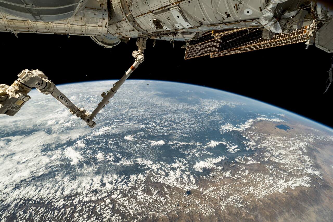 NASA. Public domain (NASA / US government work).
Overview
Section titled “Overview”Canadarm2, formally the Space Station Remote Manipulator System (SSRMS), is the primary manipulator of the International Space Station. It is one of four elements of the Mobile Servicing System, alongside the Mobile Base System, the Mobile Transporter and the Special Purpose Dexterous Manipulator [2]. It shares its heritage with the Shuttle Remote Manipulator System (SRMS) [7] but was redesigned for payloads to the mass of an orbiter and for on-orbit replacement of its major components [1], [5].
Specifications
Section titled “Specifications”| Parameter | Value | Source |
|---|---|---|
| Length | 17.6 m (57.3 ft) | [1] |
| Boom exterior diameter | 0.35 m, composite | [16] |
| Dry mass | 1497 kg | [16] |
| Degrees of freedom | 7, all identical rotary joints | [2] |
| Design payload requirement | 116,000 kg | [1] |
| End effectors | 2 identical Latching End Effectors, either usable as base | [2] |
| Power transfer through the end effector | 1800 W average, 2500 W peak | [1] |
| Data buses | 2 x MIL-STD-1553B | [1] |
| Video | up to 3 simultaneous composite NTSC channels | [2] |
| Cameras | 4, one fixed at each end and one on a pan and tilt at each elbow side | [2] |
| Lights | 4, integrated with the cameras | [2] |
| Positioning accuracy for berthing | 5 to 10 cm | [2] |
| Joint rotation range | 540 deg per joint, 270 deg either direction | [16] |
| Tip speed, unloaded | 37 cm/s | [16] |
| Tip speed, loaded under ground control | 2 cm/s | [16] |
| Tip speed, supporting a spacewalk | 15 cm/s | [16] |
Mission profile
Section titled “Mission profile”| Parameter | Value | Source |
|---|---|---|
| Host | International Space Station | [15] |
| Station orbital replacement units designated for robotic servicing | about 250 | [2] |
Kinematics
Section titled “Kinematics”Seven identical joints give a range of travel of about plus or minus 270 degrees per joint [2], [16], extended to plus or minus 281 degrees at the hard stops [1]. Six joints are sufficient to place an end effector at an arbitrary pose; the seventh makes the arm kinematically redundant, so a given end-effector pose corresponds to a continuous family of joint configurations and the arm can be routed around obstructions and through singularity-free paths [6]. Redundancy resolution is performed by the control system rather than commanded by the operator.
Both ends carry identical Latching End Effectors and either can act as base. The arm relocates by grappling a Power Data Grapple Fixture with the free end, releasing the old base, and inverting its kinematic model. The base and tip end effectors are of identical design, which is what gives the arm the operational flexibility to use either end as tip or base and so to relocate itself on the station [2]. For travel along the truss the arm rides that base on the Mobile Transporter [2]. The transporter was traded in 1987 against four requirements: traverse of every truss face including direction and plane changes, handling of payloads over 100,000 kg, up to 6 hours of self-contained operation, and control from an EVA station or from inside [5]. Continuous rails lost because they must be installed everywhere the transporter operates, and a monorail saves no mass since the higher stress on one rail returns its mass to that of a dual rail. The surviving scheme draws 9 cm, 0.4 kg node guide pins through slotted rails with discontinuous drawbars [5].
Joints and actuators
Section titled “Joints and actuators”Each joint uses a brushless permanent-magnet DC motor through a two-stage speed reducer with an overall ratio of 1845:1, with the joint parameters below [2].
| Joint parameter | Value |
|---|---|
| Gear reduction | 1845:1, two stage |
| Motor | brushless permanent magnet DC |
| Servo torque output | 1044 N m minimum |
| Brake torque, both joint motor modules engaged | 1630 N m minimum |
| Maximum joint angular velocity | 5.0 deg/s |
| Range of travel | about +/-270 deg, hard stops at +/-281 deg |
Each joint carries two identical joint motor modules, only one driven at a time, with the brakes of both engaging and disengaging together [2]. A failed module is switched out rather than repaired. Redundancy is carried through the whole arm as primary and secondary strings in power, video and control, with a back-up command string giving three control paths [2].
Joints are line-replaceable on orbit: the joint drive module and the end effector snare and rigidize mechanisms are all on-orbit replaceable units [1]. Joint components are qualified over wide temperature limits, with four levels specified:
| Component | Tightest specified range | Qualification range |
|---|---|---|
| Gears and bearings | -25 to 135 C | -50 to 155 C |
| Motor | -25 to 180 C | -50 to 200 C |
| Electronics | -25 to 99 C | -50 to 120 C |
| Cables and connectors | -70 to 135 C | -86 to 151 C (max) |
Source: [1].
Those ranges have to be held across roughly 34,000 eclipse cycles per 5.8 years of exposure, the rate measured on LDEF, where thermal cycling produced microcracking in composites and delamination of some coatings [8]. Gearbox lubricant must hold its film at 1e-4 to 1e-7 torr, where vapor pressure rather than viscosity governs the choice of fluid: a multiply alkylated cyclopentane sits at 2.3e-3 Pa at 150 C against 3.5e-6 Pa for a perfluoropolyalkylether [11].
Latching End Effector
Section titled “Latching End Effector”Capture is a three-stage sequence. Snare cables inside the end effector rotate to draw the grapple fixture probe onto the axis, a rigid ring carriage then rigidizes the interface, and four externally mounted latches engage to add preload and to allow umbilical connectors to mate for power, data and video pass-through [2].
| Parameter | Value | Source |
|---|---|---|
| Force-moment sensing | 6 axis, at the end effector | [2] |
| Snare | 3 s | [1] |
| Rigidize | 25 s | [1] |
| Latch | 60 s | [1] |
| Umbilical mate | 60 s | [1] |
| Snare plus rigidize, fast capture mode for free flyers | within 30 s | [1] |
The capture envelope accommodates 0.1 m of axial and plus or minus 0.1 m of radial misalignment of the grapple probe, with plus or minus 15 degrees in roll and plus or minus 10 degrees in pitch and yaw [1]. Interface loads are limited by design to 950 N m of bending moment when snared and rigidized with no separation, rising to 3120 N m about any axis at 3 degrees of separation. Structural margins are a yield factor of 1.1, an ultimate factor of 1.5 and a fatigue scatter factor of 4 [1].
The latches carry the load path for large payloads; the snare alone does not. A visiting vehicle is therefore captured in fast mode, which completes snare and rigidize within 30 s against the 148 s of the full snare, rigidize, latch and umbilical mate sequence [1], and is latched afterwards, because the vehicle holds its relative position under its own control only for a bounded window.
Payload handling performance
Section titled “Payload handling performance”| Condition | Tip velocity | Tip rate | Stopping distance |
|---|---|---|---|
| Unloaded arm | 0.37 m/s | 4.0 deg/s | 4.0 m |
| 20,900 kg payload | 0.022 m/s | 0.24 deg/s | 0.61 m |
| 116,000 kg payload | 0.012 m/s | 0.04 deg/s | 1.09 m |
Source: [1].
Tip speed falls by a factor of about 30 between the unloaded arm and the heaviest design payload, and stopping distance is not monotonic in payload mass: the unloaded arm coasts 4.0 m because it is fast, while a 116,000 kg payload coasts 1.09 m because it is slow [1]. Both numbers set the clearance that must be planned around structure the payload passes.
Force sensing and vision
Section titled “Force sensing and vision”Force-moment sensors at the end effectors measure contact loads in six axes [2]. They are the operator’s primary quantitative feedback, because camera views give poor depth resolution at the scale of a 20 tonne payload, and the sensor bounds the interface loads listed above. Precise position is computed photogrammetrically by the Space Vision System from targets placed on the payload [2].
Operator interface
Section titled “Operator interface”The arm is flown from Robotic Work Stations on orbit [2]. The workstation control layout was settled by evaluation at NASA JSC Building 9 from 18 to 28 January 1994 with nine NASA astronauts and one CSA astronaut, comparing hardware switches, software controls, keypad entry and on-screen controls for each function [4]. Emergency stop, brake on and off, camera pan, tilt and zoom, backup drive and backup Latching End Effector release were all required to remain hardware controls rather than software ones.
Ground control
Section titled “Ground control”Round-trip communication delay to the station is 5 to 6 seconds or more [3]. That rules out continuous force-reflecting teleoperation and drives a move-and-wait strategy in which the task is planned on the ground and a bounded segment is executed on orbit. The MARCO ground control demonstration addressed this constraint with a predictive graphical simulation of the whole robot on the ground and task-level commanding, with a sensor-driven reflex layer executing onboard [3]. It was run against the MSS Operations and Training Simulator, not against the arm on orbit [3].
The same delay is why free-flyer capture is planned around a defined capture window rather than flown reactively: the vehicle holds a fixed relative position and the arm closes on it.
Simulation and comparable arms
Section titled “Simulation and comparable arms”Spar Aerospace built MDSF for the Canadian Space Agency as a multibody simulator of flexible manipulators with contact dynamics, applied to the SSRMS and the Special Purpose Dexterous Manipulator [14]. It is documented as an architecture, with no accuracy statistics or run-time figures reported [14].
The other station arm of comparable class is the Chinese Space Station Manipulator, a seven-joint arm of 10.5 m [12], [13]. A survey of space manipulation lists its payload as 25,000 kg, with a loaded tip velocity of 0.02 m/s against 0.3 m/s unloaded, both quoted from Chinese sources without independent verification and for hardware that had not flown when the survey was written [13]. The design overview is a pre-flight paper, and its values differ slightly from the flown arm [12]. Capture is treated in the survey as four phases: observation and planning, approach, impact and grasp, and post-capture stabilization.
Environment
Section titled “Environment”External hardware on the station is exposed to the LEO environment described on the microgravity environment page: a meteoroid population with an average impact speed of 19 km/s [9], a trapped-particle single event effects environment that governs avionics design at 400 km and 51.6 degrees [10], and atomic oxygen erosion on ram-facing surfaces.
Successor
Section titled “Successor”The Canadian Space Agency lists Canadarm at 15 m and 410 kg, Canadarm2 at 17 m and 1497 kg, and the proposed Canadarm3 at 8.5 m and an estimated 715 kg [16]. Canadarm3 has not flown.
Canadarm3 is planned for the lunar Gateway. Round-trip light time at lunar distance permits supervision but not the direct hand-controller operation used on the ISS, so Canadarm3 is designed for greater onboard autonomy.
What is not established
Section titled “What is not established”The Canadarm2 dry mass, speeds and joint range come from agency web pages that state no measurement conditions or load mass, and the Canadarm3 figures are design targets, not flight values [16]. Early design documents give different arm parameters: a 1987 study quotes about 17.4 m and 860 kg for a design still in flux, against 17.6 m in the later specification [5]. The closed-form inverse kinematics are pure kinematics, without dynamics, torque or rate limits or joint travel limits, so a valid configuration is not necessarily reachable, and they were validated only in an animated environment [6]. Ground control of the station arms has been shown against a simulator, with no task times, operator study or delay-compensation error reported, so no ground-commanded operation of the arm on orbit is documented here [3]. The corpus does not hold further curated sources on Canadarm2 flight operations, on-orbit joint performance data or capture telemetry, so the page cites the works it has read and no more.
References
- Kumar, R. and Hayes, R. (1991). System requirements and design features of Space Station Remote Manipulator System mechanisms
. Aerospace Mechanisms Symposium, 19910015291. Source
BibTeX
@inproceedings{kumar1991system, title = {System requirements and design features of Space Station Remote Manipulator System mechanisms}, author = {Kumar, Rajnish and Hayes, Robert}, booktitle = {Aerospace Mechanisms Symposium}, number = {19910015291}, institution = {NASA}, year = {1991}, url = {https://ntrs.nasa.gov/citations/19910015291}, abstract = {The Space Station Remote Manipulator System (SSRMS) is a long robotic arm for handling large objects/payloads on the International Space Station Freedom. The mechanical components of the SSRMS include seven joints, two latching end effectors (LEEs), and two boom assemblies. The joints and LEEs are complex aerospace mechanisms. The system requirements and design features of these mechanisms are presented. All seven joints of the SSRMS have identical functional performance. The two LEES are identical. This feature allows either end of the SSRMS to be used as tip or base. As compared to the end effector of the Shuttle Remote Manipulator System, the LEE has a latch and umbilical mechanism in addition to the snare and rigidize mechanisms. The latches increase the interface preload and allow large payloads (up to 116,000 Kg) to be handled. The umbilical connectors provide power, data, and video signal transfer capability to/from the SSRMS.} } - Stieber, M. E., Hunter, D. G. and Abramovici, A. (1999). Overview of the Mobile Servicing System for the International Space Station
. International Symposium on Artificial Intelligence, Robotics and Automation in Space. Source
BibTeX
@inproceedings{stieber1999overview, title = {Overview of the Mobile Servicing System for the International Space Station}, author = {Stieber, M. E. and Hunter, D. G. and Abramovici, A.}, booktitle = {International Symposium on Artificial Intelligence, Robotics and Automation in Space}, address = {ESTEC, Noordwijk}, year = {1999}, url = {http://robotics.estec.esa.int/i-SAIRAS/isairas1999/s02-01.pdf} } - Landzettel, K., Brunner, B., Schreiber, G., Steinmetz, B.-M. and Dupuis, E. (2001). MSS Ground Control Demo with MARCO
. International Symposium on Artificial Intelligence, Robotics and Automation in Space. Source
BibTeX
@inproceedings{landzettel2001mss, title = {MSS Ground Control Demo with MARCO}, author = {Landzettel, Klaus and Brunner, Bernhard and Schreiber, Gerhard and Steinmetz, Bernhard-Michael and Dupuis, Eric}, booktitle = {International Symposium on Artificial Intelligence, Robotics and Automation in Space}, address = {St-Hubert, Quebec}, year = {2001}, url = {https://roboshare.esa.int/i-SAIRAS/isairas2001/papers/Paper_EU047.pdf} } - Ehrenstrom, W. A., Forrester, P. and Swaney, C. (1994). International Space Station Alpha Remote Manipulator System Workstation Controls Test Report
. NASA Johnson Space Center, NASA TM-104796. Source
BibTeX
@techreport{ehrenstrom1994international, title = {International Space Station Alpha Remote Manipulator System Workstation Controls Test Report}, author = {Ehrenstrom, William A. and Forrester, Patrick and Swaney, Colin}, number = {NASA TM-104796}, institution = {NASA Johnson Space Center}, year = {1994}, url = {https://ntrs.nasa.gov/citations/19940030975}, abstract = {Previous development testing for the space station remote manipulator system workstation controls determined the need for hardware controls for the emergency stop, brakes on/off, and some camera functions. This report documents the results of an evaluation to further determine control implementation requirements, requested by the Canadian Space Agency (CSA), to close outstanding review item discrepancies. This test was conducted at the Johnson Space Center's Space Station Mockup and Trainer Facility in Houston, Texas, with nine NASA astronauts and one CSA astronaut as operators. This test evaluated camera iris and focus, back-up drive, latching end effector release, and autosequence controls using several types of hardware and software implementations. Recommendations resulting from the testing included providing guarded hardware buttons to prevent accidental actuation, providing autosequence controls and back-up drive controls on a dedicated hardware control panel, and that 'latch on/latch off', or on-screen software, controls not be considered. Generally, the operators preferred hardware controls although other control implementations were acceptable. The results of this evaluation will be used along with further testing to define specific requirements for the workstation design.} } - Carroll, T. W. (1987). The design and development of a mobile transporter system for the Space Station Remote Manipulator System
. NASA, 19870020432. Source
BibTeX
@techreport{carroll1987design, title = {The design and development of a mobile transporter system for the Space Station Remote Manipulator System}, author = {Carroll, Thomas W.}, number = {19870020432}, institution = {NASA}, year = {1987}, url = {https://ntrs.nasa.gov/citations/19870020432}, abstract = {The analyses, selection process, and conceptual design of potential candidate Mobile Transporter (MT) systems to move the Space Station Remote Manipulator System (SSRMS) about the exposed faces of the Space Station truss structure are described. The actual requirements for a manipulator system on the space station are discussed, including potential tasks to be performed. The SSRMS operating environment and control methods are analyzed with potential design solutions highlighted. Three general categories of transporter systems are identified and analyzed. Several design solution have emerged that will satisfy these requirements. Their relative merits are discussed, and unique variations in each system are rated for functionality.} } - Crane, C. D. I., Duffy, J. and Carnahan, T. (1991). A kinematic analysis of the Space Station remote manipulator system (SSRMS)
. Journal of Robotic Systems, 19910069677. Source
BibTeX
@article{crane1991kinematic, title = {A kinematic analysis of the Space Station remote manipulator system (SSRMS)}, author = {Crane, Carl D., III and Duffy, Joseph and Carnahan, Tim}, journal = {Journal of Robotic Systems}, volume = {8}, number = {19910069677}, pages = {637-658}, institution = {NASA}, year = {1991}, doi = {10.1002/rob.4620080505}, abstract = {Abstract An efficient reverse analysis of three 6‐degree‐of‐freedom (dof) subchains of the 7‐dof SSRMS is presented. The first subchain is formed by locking the seventh joint. The second subchain is formed by locking the second joint, while the third subchain is formed by locking the first joint (the grounded joint is counted as the first joint in the chain). There are a maximum of eight different arm configurations in each of the three subchains, and these were determined by employing a computer‐efficient algorithm, which required the rooting of only at most quadratic polynomials. The algorithms were implemented, and the SSRMS was employed in an animated environment to perform and practice a number of useful tasks for space station servicing. The locking of the second joint has the advantage in that an operator could, at the outset, choose the orientation of the plane that contains the two longest links (the upper arm and forearm) so as to avoid collisions with obstacles. However, it has the disadvantage that when the second joint angle equals 0° or 180°, the manipulator is in a singularity configuration (a singularity analysis of the SSRMS is presented in a second article). It is interesting to note that this plane can also be oriented by specifying the first joint angle. This has the distinct advantage that the plane can be oriented arbitrarily and, in this way, the singularity is avoided.} } - Jorgensen, G. and Bains, E. (2011). SRMS History, Evolution and Lessons Learned
. AIAA SPACE Conference, 20110015563. Source
BibTeX
@inproceedings{jorgensen2011srms, title = {SRMS History, Evolution and Lessons Learned}, author = {Jorgensen, Glenn and Bains, Elizabeth}, booktitle = {AIAA SPACE Conference}, number = {20110015563}, institution = {NASA}, year = {2011}, doi = {10.2514/6.2011-7277}, abstract = {Early in the development of the Space Shuttle, it became clear that NASA needed a method of deploying and retrieving payloads from the payload bay. The Shuttle Remote Manipulator System (SRMS) was developed to fill this need. The 50 foot long robotic arm is an anthropomorphic design consisting of three electromechanical joints, six degrees of freedom, and two boom segments. Its composite boom construction provided a light weight solution needed for space operations. Additionally, a method of capturing payloads with the arm was required and a unique End Effector was developed using an electromechanical snare mechanism. The SRMS is operated using a Displays and Controls Panel and hand controllers located within the aft crew compartment of the shuttle. Although the SRMS was originally conceived to deploy and retrieve payloads, its generic capabilities allowed it to perform many other functions not originally conceived of. Over the years it has been used for deploying and retrieving constrained and free flying payloads, maneuvering and supporting EVA astronauts, satellite repair, International Space Station construction, and as a viewing aid for on-orbit International Space Station operations. After the Columbia accident, a robotically compatible Orbiter Boom Sensor System (OBSS) was developed and used in conjunction with the SRMS to scan the Thermal Protection System (TPS) of the shuttle. These scans ensure there is not a breach of the TPS prior to shuttle re-entry. Ground operations and pre mission simulation, analysis and planning played a major role in the success of the SRMS program. A Systems Engineering Simulator (SES) was developed to provide a utility complimentary to open loop engineering simulations. This system provided a closed-loop real-time pilot-driven simulation giving visual feedback, display and control panel interaction, and integration with other vehicle systems, such as GN&C. It has been useful for many more applications than traditional training. Evolution of the simulations, guided by the Math Model Working Group, showed the utility of input from multiple modeling groups with a structured forum for discussion.There were many unique development challenges in the areas of hardware, software, certification, modeling and simulation. Over the years, upgrades and enhancements were implemented to increase the capability, performance and safety of the SRMS. The history and evolution of the SRMS program provided many lessons learned that can be used for future space robotic systems.} } - Stein, B. A. (1992). An interim overview of LDEF materials findings
. NASA, NASA-TM-107664. Source
BibTeX
@techreport{stein1992interim, title = {An interim overview of LDEF materials findings}, author = {Stein, Brad A.}, number = {NASA-TM-107664}, institution = {NASA}, year = {1992}, url = {https://ntrs.nasa.gov/citations/19930009140}, abstract = {The flight and retrieval of the National Aeronautics and Space Administration's Long Duration Exposure Facility (LDEF) provided an opportunity for the study of the low-Earth orbit (LEO) environment and long-duration space environmental effects (SEE) on materials that is unparalleled in the history of the U.S. Space Program. The remarkable flight attitude stability of LDEF enables specific analyses of various individual and combined effects of LEO environmental parameters on identical materials on the same space vehicle. This paper provides an overview of the interim LDEF materials findings of the Principal Investigators and the Materials Special Investigation Group. In general, the LDEF data is remarkably consistent; LDEF will provide a 'benchmark' for materials design data bases for satellites in low-Earth orbit. Some materials were identified to be encouragingly resistant to LEO SEE for 5.8 years; other 'space qualified' materials displayed significant environmental degradation. Molecular contamination was widespread; LDEF offers an unprecedented opportunity to provide a unified perspective of unmanned LEO spacecraft contamination mechanisms. New material development requirements for long-term LEO missions have been identified and current ground simulation testing methods/data for new, durable materials concepts can be validated with LDEF results. LDEF findings are already being integrated into the design of Space Station Freedom.} } - Moorhead, A. V. (2020). NASA Meteoroid Engineering Model (MEM) Version 3
. NASA, NASA/TM-2020-220555. Source
BibTeX
@techreport{moorhead2020nasa, title = {NASA Meteoroid Engineering Model (MEM) Version 3}, author = {Moorhead, A. V.}, number = {NASA/TM-2020-220555}, institution = {NASA}, year = {2020}, url = {https://ntrs.nasa.gov/citations/20200000563}, abstract = {The Meteoroid Engineering Model (MEM) version 3 is NASA’s most current and accurate model of the meteoroid environment. MEM 3 supersedes all previous versions of MEM, including MEM Release 2.0 (MEMR2), MEM Release 1.0c (MEMR1c), and previously internally controlled and released versions of MEMCxP v2.0 and LunarMEM v2.0. Earlier versions of MEM superseded older models of the meteoroid environment such as the Grün model and its derivative, Technical Memo 4527 (hereafter abbreviated as TM 4527) [1]. Prior to the establishment of the NASA Meteoroid Environment Office (MEO), NASA’s meteoroid environment models relied on a simple empirical expression derived from [2], as described in [3] and later in [1]. This expression describes the meteoroid flux incident on a flat plate near 1 au. TM 4527 assumes an isotropic environment, making the orientation of the plate irrelevant [4]. The flux was combined with scale factors to account for the reduction in flux occurring when the Earth shields the spacecraft from a portion of the meteoroid environment and the enhancement in flux due to the focusing effect of Earth’s gravitational field. TM 4527 also introduced a crude, piecewise meteoroid speed distribution with an average velocity of 19 km/s for an orbiting spacecraft based on [5]. Finally, TM 4527 assumed a three-step density distribution in which dust particles smaller than 10−6 g have a density of 2 g/cu cm, micrometeoroids between 10−6 g and 0.01 g have a density of 1 g/cu cm, and meteoroids larger than 0.01 g have a density of 0.5 g/cm3. Thus, the meteoroid model presented in TM 4527 was assembled from multiple independent sources. The model of TM 4527 was also used for years in Space Station risk assessments, and is described in Space Station Specification (SSP) 30425.} } - Koontz, S. L., Suggs, R. M., Alred, J. W., Worthy, E. S., Boeder, P., Steagall, C. A., Hartman, W. A., Gingras, B. D. and Schmidl, W. D. (2018). The International Space Station Space Radiation Environment: Avionics Systems Performance in Low-Earth Orbit Single Event Effects (SEE) Environments
. International Conference on Environmental Systems, ICES-2018-69. Source
BibTeX
@inproceedings{koontz2018international, title = {The International Space Station Space Radiation Environment: Avionics Systems Performance in Low-Earth Orbit Single Event Effects (SEE) Environments}, author = {Koontz, Steven L. and Suggs, Robert M. and Alred, John W. and Worthy, Erica S. and Boeder, Paul and Steagall, Courtney A. and Hartman, William A. and Gingras, Benjamin D. and Schmidl, William D.}, booktitle = {International Conference on Environmental Systems}, number = {ICES-2018-69}, address = {Albuquerque, New Mexico}, year = {2018}, url = {https://ttu-ir.tdl.org/items/7fb5d403-ad77-4f6b-9cff-c70af5c04802} } - Jones, W. R. J., Jansen, M. J., Gschwender, L. J., Snyder, C. E. J., Sharma, S. K., Predmore, R. E. and Dube, M. J. (2001). The Tribological Properties of Several Silahydrocarbons for Use in Space Mechanisms
. Journal of Synthetic Lubrication, NASA/TM-2001-211196. Source
BibTeX
@article{jones2001tribological, title = {The Tribological Properties of Several Silahydrocarbons for Use in Space Mechanisms}, author = {Jones, W. R., Jr. and Jansen, M. J. and Gschwender, L. J. and Snyder, C. E., Jr. and Sharma, Shiv K. and Predmore, R. E. and Dube, Michael J.}, journal = {Journal of Synthetic Lubrication}, volume = {20}, number = {NASA/TM-2001-211196}, pages = {303-315}, institution = {NASA}, address = {Liege}, year = {2001}, doi = {10.1002/jsl.3000200404}, abstract = {Abstract Silahydrocarbons are members of a relatively new class of liquid lubricants with great potential for use in space mechanisms. They are unimolecular species consisting of silicon, carbon, and hydrogen. They possess unique wear, viscosity, and volatility properties while retaining the ability to solubilise conventional additives. The tribological properties of several members of this class, including tri‐, tetra‐, and penta‐compounds, are presented. These properties include viscosity‐temperature, viscosity—pressure, vapour pressure, lubricant life, traction, and reciprocating and four‐ball wear rates. Lubricant lifetimes were determined using a vacuum ball bearing simulator, the spiral orbit tribometer. Wear was measured using a Cameron Plint reciprocating tribometer and wear rates with a vacuum four‐ball tribometer. Conventional viscometry was used for viscosity—temperature measurements and a Knudsen cell for vapour pressure. Thermogravimetric analysis was also used for volatility measurements. Pressure—viscosity coefficients (α—values) were estimated from elastohydrodynamic lubrication film thickness measurements. These properties are compared to those of existing state‐of‐the‐art space lubricants.} } - Li, D. and Wang, Y. (2015). Overview of the Chinese Space Station Manipulator
. AIAA SPACE Conference. Source
BibTeX
@inproceedings{li2015overview, title = {Overview of the Chinese Space Station Manipulator}, author = {Li, Daming and Wang, Yaobing}, booktitle = {AIAA SPACE Conference}, year = {2015}, doi = {10.2514/6.2015-4540}, abstract = {The Chinese Space Station Manipulator system (CSSM) is designed for the missions of relocking spacecraft sections, docking assistance, installing equipment, and maintaining the space station. Therefore, it will lay a foundation for the construction of the Chinese Space Station (CSS). The CSSM system, consisting of two robotic arms, is featured with a high degree of manipulation accuracy, reliability and load capability. Since it is a highly integrated robotic system, combining technologies of mechanics, electronics, thermotics, vision and computer control, the development of the Space Station faces many technical challenges and, therefore, the design and implementation of the robotic system is also challenging. This paper presents an introduction of the Core Space Station Cabin’s Manipulator (CSSCM) which is also referred to as the Chinese Space Station Manipulator. As the major arm of the two-arm CSSM system, the manipulator is a seven degree-of-freedom redundant arm with a distributed control system and movable base system. The paper also describes highlights of eight key technologies of the robotic arm, such as a high-precision servo control and a multi-constrained trajectory planning capability. Our study has shown that the CSSCM design has satisfactorily completed and the program has entered into the manufacturing phase.} } - Papadopoulos, E., Aghili, F., Ma, O. and Lampariello, R. (2021). Robotic Manipulation and Capture in Space: A Survey
. Frontiers in Robotics and AI. Source
BibTeX
@article{papadopoulos2021robotic, title = {Robotic Manipulation and Capture in Space: A Survey}, author = {Papadopoulos, Evangelos and Aghili, Farhad and Ma, Ou and Lampariello, Roberto}, journal = {Frontiers in Robotics and AI}, volume = {8}, pages = {686723}, year = {2021}, doi = {10.3389/frobt.2021.686723}, abstract = {Space exploration and exploitation depend on the development of on-orbit robotic capabilities for tasks such as servicing of satellites, removing of orbital debris, or construction and maintenance of orbital assets. Manipulation and capture of objects on-orbit are key enablers for these capabilities. This survey addresses fundamental aspects of manipulation and capture, such as the dynamics of space manipulator systems (SMS), i.e., satellites equipped with manipulators, the contact dynamics between manipulator grippers/payloads and targets, and the methods for identifying properties of SMSs and their targets. Also, it presents recent work of sensing pose and system states, of motion planning for capturing a target, and of feedback control methods for SMS during motion or interaction tasks. Finally, the paper reviews major ground testing testbeds for capture operations, and several notable missions and technologies developed for capture of targets on-orbit.} } - Ma, O., Buhariwala, K., Roger, N., MacLean, J. and Carr, R. (1997). MDSF — A generic development and simulation facility for flexible, complex robotic systems
. Robotica. Source
BibTeX
@article{ma1997mdsf, title = {MDSF — A generic development and simulation facility for flexible, complex robotic systems}, author = {Ma, Ou and Buhariwala, Kerman and Roger, Neil and MacLean, John and Carr, Robert}, journal = {Robotica}, volume = {15}, pages = {49-62}, year = {1997}, doi = {10.1017/s0263574797000076}, abstract = {MDSF is a generic manipulator development and simulation facility developed by Spar Aerospace Limited, as a prime contractor to the Canadian Space Agency. It is an integral part of Canada's contribution to the International Space Station (ISS) program. MDSF is capable of simulating general robotic systems with complex and flexible structures undergoing all kinds of tasks including payload hand-over and contact with the environment. Rigorous validation and configuration control have been imposed throughout the development course of the simulation facility. Examples of current applications in the ISS program are included.} } - (2026). CSA: Canadarm2. asc-csa.gc.ca/eng/iss/canadarm2
BibTeX
@misc{csacanadarm2, title = {CSA: Canadarm2}, organization = {asc-csa.gc.ca}, year = {2026}, url = {https://www.asc-csa.gc.ca/eng/iss/canadarm2/} } - (2026). CSA: Comparative table of Canadarm, Canadarm2 and Canadarm3. asc-csa.gc.ca/eng/iss/canadarm2/canadarm-canadarm2-canadarm3-comparat...
BibTeX
@misc{csacomparative,
  title = {CSA: Comparative table of Canadarm, Canadarm2 and Canadarm3},
  organization = {asc-csa.gc.ca},
  year = {2026},
  url = {https://www.asc-csa.gc.ca/eng/iss/canadarm2/canadarm-canadarm2-canadarm3-comparative-table.asp}
}