Orbital Express
Program pages DARPA: Orbital Express
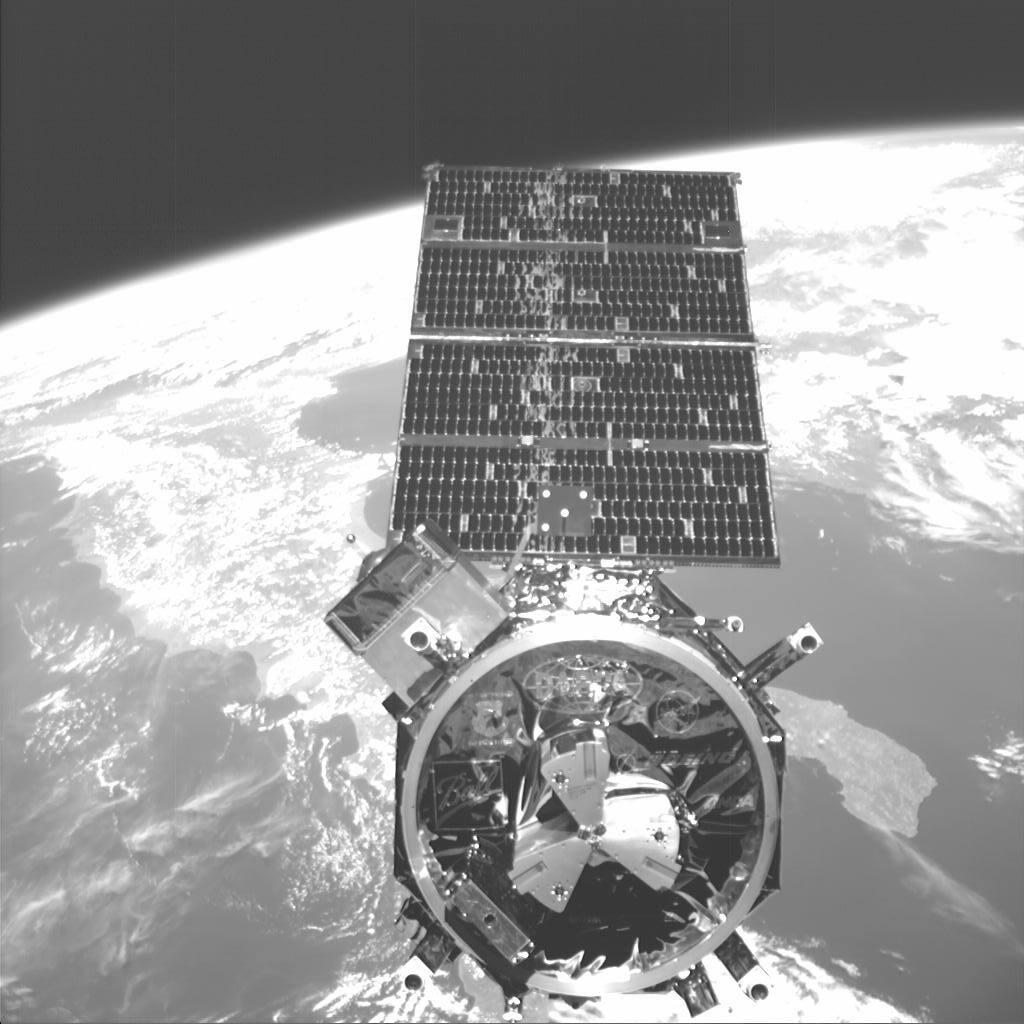 DARPA. Public domain (US government work).
The problem
Section titled “The problem”A servicer has to find a client satellite, close on it, make contact, and exchange propellant or hardware with it, all without a crew and, for most of the work, without a human in the control loop. The orbit sets the conditions. Contact between two free-flying vehicles happens faster than a ground loop can respond, and at 492 km an eclipse is entered roughly every 90 minutes, the cadence that produced about 34,000 thermal cycles in 5.8 years on LDEF [8]. Radiation hardening at that altitude and a 46 degree inclination is driven by single event effects from trapped protons rather than total dose [7].
Crewed practice shows the alternative. Space Shuttle rendezvous and proximity operations stayed crew-flown in translation and hand-controlled at close range for three decades. The flight dynamics organization that ran them attributes this to the absence of a programmatic requirement for automation and the cost of certifying safety-critical flight software, and argues that continuous out-the-window observation was needed to catch off-nominal relative motion [10].
The economic case is argued from GEO statistics: roughly 500 commercial GEO satellites in a 2000 to 2015 forecast and about 25 retirements a year from propellant depletion [18]. Mission-design studies of a GEO servicer find that sequences beginning with repair and later adding refueling, observation and retirement carry the most value; these are simulation results with assumed costs and failure rates [17].
What has flown
Section titled “What has flown”ROTEX (1993). A teleoperated arm inside Spacelab, with ground control compensating a 5 to 7 s round-trip delay by predictive simulation [13].
ETS-VII. Flown in 1998 and 1999 [11], it made the first autonomous rendezvous and docking of two unmanned spacecraft, in two experiments in July and August 1998. It closed at 1 cm/s with a measured peak deceleration of 9 mm/s^2, and the second flight was recovered after thruster anomalies caused repeated safety-mode aborts [11]. Its rendezvous laser radar was the primary sensor from 500 m to 2 m, with a specified range of 0.3 to 660 m, and showed a line-of-sight bias at docking of 0.09 deg against a 0.05 deg specification [12]. In the 1999 GETEX experiments DLR ran 110 minutes of dynamic motion experiments with the ETS-VII arm, 52 minutes of them with the satellite attitude uncontrolled, under a 1.0 deg per axis attitude limit [13]. The arm was 2 m long and worked against a target the chaser had released itself [6].
ROKVISS (from 2005). A two-joint DLR manipulator on the ISS measured about 50 percent more joint friction on orbit than at a 20 degC ground reference [14].
Orbital Express (2007). DARPA’s demonstration was flown to establish servicing by machines [1]. ASTRO, the servicer, was built by Boeing Phantom Works, which also supplied the guidance, navigation and control system [1], [2]. NEXTSat, the client, was built by Ball Aerospace on its RS-300 bus and acted both as a satellite needing service and as a commodities depot [1]. The program validated the feasibility of robotic autonomous refueling and reconfiguration [33], and DARPA still cites it for that [34].
Launch was on an Atlas V from Cape Canaveral on 8 March 2007 with both vehicles mated, into a 492 by 492 km, 46 degree orbit; ASTRO was decommissioned on 22 July 2007 [2]. Five captures were flown, three direct and two by grapple and berth, and the arm transferred a lithium-ion battery between the vehicles and replaced the operational flight computer, individually and in combination without ground assistance [2]. Refueling demonstrations ran before the first separation and after each capture [2]. Hydrazine transfer showed 5 to 10 percent flow rate error with no anomalies [6]. Nine mate and demate cycles were completed on orbit [6]. Orbital Express added what the earlier flights lacked: autonomous rendezvous from hundreds of kilometers, capture of an unconstrained free flyer, propellant transfer and exchange of functioning avionics between two spacecraft that were not a released pair [6].
Hardware. The Orbital Express Demonstration Manipulator System was a 6 DOF arm of 2.8 m reach built by MDA, ending in a mouse-trap, cone and probe interface with an end effector camera [6], [1]. The 2003 description gave a maximum reach near 3.3 m within a design family scalable from 3 m to 6 m [1]. The Starsys Research docking mechanism, now marketed by Sierra Space, is a three-arm grapple on a motor-driven lead screw that draws the passive half into a three-point kinematic mount; preload is set when a mechanical torque sensor trips limit switches and a brake holds the load, and fluid and electrical couplings sit inside the ring [5], [33]. Soft docking was chosen over impact docking, harpoon and probe designs so contact forces stay low enough to align the couplings [5]. Qualification used more than 200 offload mate and demate cycles, over 400 simulated capture cases, hydraulic hexapod testing and KC-135 flights with a 25 s free-float window [5].
Autonomy and sensing. The program defined four supervised-autonomy levels, from ground approval before execution to full automation with ground analysis only on a problem; Draper Laboratory supplied the onboard mission manager [1], [2]. ASTRO carried three visible cameras, an infrared camera, a long-range lidar and the Advanced Video Guidance Sensor [1]. AVGS fires 800 nm and 850 nm laser diodes in turn at filtered retroreflectors, subtracts the two images to remove background, and recovers 6 DOF pose at 5 Hz over a plus or minus 8 degree field of view [3]. Boeing’s Vis-STAR computed azimuth, elevation and range from camera imagery, and attitude where natural features allowed, without cooperative markings [2]. Plans were generated by JPL’s ASPEN against ground-station contact rules, including a 60 minute reuse delay for a ground string [9]. Command ran from the AFRL support center at Kirtland, with Boeing support rooms in Huntington Beach and Houston [2]. In flight, AVGS tracked its short-range target to 31.6 m during 30 m unmated operations and acquired the long-range target at 150 m during a recovery approach, past the planned 120 m limit; the shortfall beyond 150 m is attributed to ground optical testing capped at 100 m against a 200 m requirement [3], [4].
ELSA-d (2021 to 2022). Astroscale launched a 175 kg servicer and a 17 kg client with a ferromagnetic docking plate into a 550 km orbit in March 2021 to demonstrate capture of a stable client, capture of a tumbling client, and diagnosis, loss and re-acquisition [22]. In the autonomous capture demonstration begun 25 January 2022 the servicer held a 30 m separation for more than seven hours using relative station keeping, before anomalous spacecraft conditions led to abandonment of the capture attempt; reacquisition of the client at long range and handover from absolute to relative navigation were demonstrated [21], [32].
MEV (GEO, commercial). Northrop Grumman’s Mission Extension Vehicles carry visible, long-wave infrared and scanning lidar sensors. Imagery of Intelsat 901 and Intelsat 10-02 shows visible detection beyond 30 km, infrared beyond 10 km, and a full 6 DOF solution from 60 m to 2 m; the lidar was modified with reduced beam divergence because the clients carry no retroreflectors [24]. The record is imagery, not error statistics, and covers two large cooperative-geometry clients [24].
ADRAS-J. Astroscale’s spacecraft closed from 50 m to roughly 15 m below an unprepared H-IIA upper stage on 11 December 2024 [20]. It did not reach the capture initiation point: the onboard collision avoidance triggered an autonomous abort after a relative attitude anomaly [20]. No capture of an unprepared object has been flown.
What is being tried now
Section titled “What is being tried now”Capture of unprepared and tumbling objects. ADRIOS ClearSpace-1 is designed to capture the 94 kg PROBA-1 with a ladder of reversible approach steps, sized for one rehearsal and three capture attempts, with launch expected at the end of 2028; it is a design, with no measured performance [23]. Control work for the tumbling case is in simulation: a geometric observer and controller for a fully actuated servicer approaching a tumbling target in one scenario [29], and a decentralized model predictive scheme for three servicers docking to a tumbling target, converging in 20 to 25 s in a single 40 s run [30]. CSA captured a two-thirds scale tumbling mock-up with two 7-DOF arms and a laser camera on the ground, reporting success without trial counts or errors; its 0.01 m, 1 deg, 0.01 m/s and 1 deg/s figures are requirements, not results [15].
Servicing on a program scale. NASA’s OSAM-1 began in 2015 as RESTORE-L, was forecast at no more than 750 million dollars for a 2020 launch, and had spent about 1.4 billion dollars by November 2023 against an estimate at completion of 2.38 billion and a 70 percent confidence launch date of March 2028; the review board’s report ended it, and noted refueling a legacy valve was seen as low value next to dexterous servicing and assembly [19]. The ISS Dextre Pointing Package, which would have tested servicing sensors on the station arm, was planned for 2012 and never flown [27]. NASA’s catalog places 145 developers in 21 countries in servicing, assembly and manufacturing and keeps an 8 m boundary between long and short manipulators; the 2.8 m Orbital Express arm is short [16], [6]. The 2021 edition describes a shift from bespoke human-operated arms toward proliferated low cost autonomous robotics [6]. These catalog editions overlap heavily and are not independent sources [6], [16].
Autonomy for proximity operations. An architecture for a small free-flying inspector near the Lunar Gateway, with keep-in corridors, keep-out hulls and a receding-horizon planner, was exercised only in MuJoCo simulation, including with four thrusters failed [26]. A proposal to reuse the MRV rendezvous cameras for space domain awareness predicts detection ranges from a model, with one qualitative MEV-2 frame as the only on-orbit evidence [31].
Ground testing of contact. DLR’s OOS-SIM drives two KUKA KR120 robots as servicer and client with real-time free-floating dynamics, over a common workspace of about 23.28 m3, validated against its own offline simulation and not against flight [28]. A 2024 survey inventories the other facilities, among them ESA’s ORBIT flat floor, DLR’s EPOS 2.0 for tumbling targets and NASA’s 21.3 by 29.9 m air-bearing floor at Johnson [25].
The numbers
Section titled “The numbers”| Parameter | Value | Source |
|---|---|---|
| Arm | Orbital Express Demonstration Manipulator System, 6 DOF, 2.8 m reach, MDA | [6] |
| Arm design family | scalable 3 m to 6 m, maximum reach about 3.3 m in the 2003 description | [1] |
| Arm end effector | mouse-trap cone and probe, with an end effector camera | [6], [1] |
| Docking mechanism | three-arm grapple, motor-driven lead screw, Starsys Research | [5] |
| Docking axial capture distance | 15 cm | [5] |
| Docking angular misalignment tolerance | +/-5 deg in pitch, yaw and roll | [5] |
| Docking lateral misalignment tolerance | +/-5 cm | [5] |
| Docking contact velocity tolerance | 3 cm/s | [5] |
| Mated preload | 11,250 N | [5] |
| Capture time | under 10 s; capture and latch under 240 s | [5] |
| Docking interface outer diameter | under 46 cm | [5] |
| Docking mechanism mass | under 23 kg active, under 11.5 kg passive | [5] |
| Launch | Atlas V, 8 March 2007, both spacecraft mated | [2] |
| Orbit | 492 by 492 km at 46 degrees | [2] |
| Decommissioned | 22 July 2007 | [2] |
| Captures flown | 5 (3 direct, 2 grapple and berth) | [2] |
| Mate and demate cycles flown | 9 | [6] |
| Orbital replacement units transferred | 2: a lithium-ion battery and a flight computer | [1], [6] |
| ASTRO hydrazine loaded | 72 kg, of which 37 kg designed for transfer | [1] |
| NEXTSat fluid transfer module tank | 34 kg capacity | [1] |
| Hydrazine transfer flow rate error | 5 to 10 percent, no anomalies | [6] |
| ASTRO power | deployable gimballed arrays, two 33 A h lithium-ion batteries | [1] |
| ASTRO processor | radiation-hardened PowerPC 750, IEEE-1394 network | [1] |
| AVGS output and field of view | 5 Hz, plus or minus 8 deg | [3] |
| AVGS flight tracking | short-range target to 31.6 m; long-range acquired at 150 m | [3] |
| Ground test before flight | 25 s KC-135 window, over 200 offload cycles, over 400 simulated captures | [5] |
| Robotic manipulator reach: Canadarm / Canadarm2 / Dextre / ERA | 15 m / 17.6 m / 3.35 m / 11.3 m | [6] |
What is not established
Section titled “What is not established”The published record does not give the arm’s joint, gearbox or motor design, any arm force or moment measurement, or NEXTSat’s power system. Docking qualification reports that the model matched test and captures succeeded, but no measured contact loads, stiffness values or capture success curve against initial condition [5]. The mechanism was never exercised against an uncooperative target: the passive half was always held inside a stationkeeping envelope, so nothing here bounds capture of a tumbling client [5]. NEXTSat carried retroreflectors, grapple fixtures, a matched docking interface and a crosslink radio, and relative navigation against targets with none of those was not demonstrated at all ranges [2]. Vendor figures for the as-flown unit differ from the development requirement table (capture and latch under 300 s against 240 s) without explanation [33], [5]. AVGS performance beyond 100 m rests on extrapolation from ground tests capped below the 200 m requirement [4].
The commercial flights are documented by operator releases and design papers: ELSA-d and ADRAS-J give no station-keeping error or sensor accuracy and describe the anomalies only as such [21], [20], and the ELSA-d design paper gives no capture envelope or tumble rate limit [22]. The tumbling-target control results above are single simulations with no hardware [29], [30].
References
- Shoemaker, J., Wright, M. and Sivapiragasam, S. (2003). Orbital Express Space Operations Architecture Program
. Annual AIAA/USU Conference on Small Satellites, SSC03-IV-2. Source
BibTeX
@inproceedings{shoemaker2003orbital, title = {Orbital Express Space Operations Architecture Program}, author = {Shoemaker, James and Wright, Melissa and Sivapiragasam, Sanjivan}, booktitle = {Annual AIAA/USU Conference on Small Satellites}, number = {SSC03-IV-2}, year = {2003}, url = {https://digitalcommons.usu.edu/smallsat/2003/all2003/62/} } - Naasz, B., Zimpfer, D., Barrington, R. and Mulder, T. (2010). Flight Dynamics and GN&C for Spacecraft Servicing Missions
. AIAA/AAS Astrodynamics Specialist Conference, 20180000051. Source
BibTeX
@inproceedings{naasz2010flight, title = {Flight Dynamics and GN&C for Spacecraft Servicing Missions}, author = {Naasz, Bo and Zimpfer, Doug and Barrington, Ray and Mulder, Tom}, booktitle = {AIAA/AAS Astrodynamics Specialist Conference}, number = {20180000051}, institution = {NASA}, year = {2010}, doi = {10.2514/6.2010-8445}, abstract = {Future human exploration missions and commercial opportunities will be enabled through In-space assembly and satellite servicing. Several recent efforts have developed technologies and capabilities to support these exciting future missions, including advances in flight dynamics and Guidance, Navigation and Control. The Space Shuttle has demonstrated significant capabilities for crewed servicing of the Hubble Space Telescope (HST) and assembly of the International Space Station (ISS). Following the Columbia disaster NASA made significant progress in developing a robotic mission to service the HST. The DARPA Orbital Express mission demonstrated automated rendezvous and capture, In-space propellant transfer, and commodity replacement. This paper will provide a summary of the recent technology developments and lessons learned, and provide a focus for potential future missions.} } - Howard, R., Heaton, A., Pinson, R. and Carrington, C. (2008). Orbital Express Advanced Video Guidance Sensor
. IEEE Aerospace Conference, 20090001151. Source
BibTeX
@inproceedings{howard2008orbital, title = {Orbital Express Advanced Video Guidance Sensor}, author = {Howard, Ricky and Heaton, Andy and Pinson, Robin and Carrington, Connie}, booktitle = {IEEE Aerospace Conference}, number = {20090001151}, pages = {1-10}, institution = {NASA}, year = {2008}, doi = {10.1109/aero.2008.4526518}, abstract = {In May 2007 the first US-sponsored fully autonomous rendezvous and capture was successfully performed by DARPA's Orbital Express (OE) mission. For the following three months, the Boeing ASTRO spacecraft and the Ball Aerospace NEXTSat performed multiple rendezvous and docking maneuvers to demonstrate some of the technologies needed for satellite servicing. MSFC's advanced video guidance sensor (AVGS) was a near-field proximity operations sensor integrated into ASTRO's Autonomous Rendezvous and Capture Sensor System (ARCSS), which provided relative state knowledge to the ASTRO GN&C system. AVGS was one of the primary docking sensors included in ARCSS. This paper provides an overview of the AVGS sensor that flew on orbital express, a summary of the AVGS ground testing, and a discussion of AVGS performance on-orbit for OE. The AVGS is a laser-based system that is capable of providing bearing at midrange distances and full six degree- of-freedom (6-DOF) knowledge at near ranges. The sensor fires lasers of two different wavelengths to illuminate retro- reflectors on the long range target (LRT) and the Short Range Target (SRT) mounted on NEXTSat. The retro- reflector filters allow one laser wavelength to pass through and be reflected, while blocking the other wavelength. Subtraction of one return image from the other image removes extraneous light sources and reflections from anything other than the corner cubes on the LRT and SRT. The very bright spots that remain in the subtracted image are processed to provide bearing or 6-DOF relative state information. AVGS was operational during the Orbital Express unmated scenarios and the sensor checkout operations. The OE unmated scenarios ranged from 10 meters to 7 kilometers ending in either a docking or a free-flyer capture. When the target was pointed toward the AVGS and in the AVGS operating range and field-of-view (i.e. along the approach corridor of the NEXTSat), the AVGS provided full 6-DOF measurements. The AVGS performed very well during the sensor check-out operations, effectively tracking beyond its 10-degree Pitch and Yaw limit-specifications. AVGS also provided excellent performance during the unmated operations, effectively tracking its targets, and showing good agreement between the SRT and LRT data. The AVGS consistently exceeded the tracking range expectations for both the SRT and LRT. During the approach to re-mate in scenario 3-1 recovery the AVGS began tracking the LRT at 150 m, well beyond the OE specified operational range of 120 meters, and functioned as the primary sensor for the autonomous rendezvous and docking. For all scenarios, the AVGS was used while ASTRO was in the approach corridor to NEXTSat, and during close proximity operations and docking.} } - Pinson, R. M., Howard, R. T. and Heaton, A. F. (2008). Orbital Express Advanced Video Guidance Sensor: Ground Testing, Flight Results and Comparisons
. AIAA Guidance, Navigation, and Control Conference, 20080048264. Source
BibTeX
@inproceedings{pinson2008orbital, title = {Orbital Express Advanced Video Guidance Sensor: Ground Testing, Flight Results and Comparisons}, author = {Pinson, Robin M. and Howard, Richard T. and Heaton, Andrew F.}, booktitle = {AIAA Guidance, Navigation, and Control Conference}, number = {20080048264}, institution = {NASA}, year = {2008}, doi = {10.2514/6.2008-7318}, abstract = {Orbital Express (OE) was a successful mission demonstrating automated rendezvous and docking. The 2007 mission consisted of two spacecraft, the Autonomous Space Transport Robotic Operations (ASTRO) and the Next Generation Serviceable Satellite (NEXTSat) that were designed to work together and test a variety of service operations in orbit. The Advanced Video Guidance Sensor, AVGS, was included as one of the primary proximity navigation sensors on board the ASTRO. The AVGS was one of four sensors that provided relative position and attitude between the two vehicles. Marshall Space Flight Center was responsible for the AVGS software and testing (especially the extensive ground testing), flight operations support, and analyzing the flight data. This paper briefly describes the historical mission, the data taken on-orbit, the ground testing that occurred, and finally comparisons between flight data and ground test data for two different flight regimes.} } - Christiansen, S. and Nilson, T. (2008). Docking System Mechanism Utilized on Orbital Express Program
. Aerospace Mechanisms Symposium, NASA Marshall Space Flight Center. Source
BibTeX
@inproceedings{christiansen2008docking, title = {Docking System Mechanism Utilized on Orbital Express Program}, author = {Christiansen, Scott and Nilson, Troy}, booktitle = {Aerospace Mechanisms Symposium, NASA Marshall Space Flight Center}, year = {2008}, url = {https://www.esmats.eu/amspapers/pastpapers/pdfs/2008/christiansen.pdf} } - Arney, D., Sutherland, R., Mulvaney, J., Steinkoenig, D., Stockdale, C. and Farley, M. (2021). On-orbit Servicing, Assembly, and Manufacturing (OSAM) State of Play, 2021 Edition
. NASA, 20210022660. Source
BibTeX
@techreport{arney2021orbit, title = {On-orbit Servicing, Assembly, and Manufacturing (OSAM) State of Play, 2021 Edition}, author = {Arney, Dale and Sutherland, Richard and Mulvaney, John and Steinkoenig, Devon and Stockdale, Christopher and Farley, Mason}, number = {20210022660}, institution = {NASA}, year = {2021}, url = {https://ntrs.nasa.gov/citations/20210022660}, abstract = {This document compiles and organizes the current state of OSAM missions, capabilities, and developments. Understanding where the set of capabilities currently stand will help mission designers incorporate OSAM technologies into their concepts, create the starting point for technology development plans and roadmaps, and provide technologists a survey of the field they are developing. The authors recognize that this capability is broad and that they are unlikely to have captured everything that has been or is being done in the area on the first attempt. As a result, a new version of the OSAM State of Play will be released periodically (perhaps annually).} } - Koontz, S. L., Suggs, R. M., Alred, J. W., Worthy, E. S., Boeder, P., Steagall, C. A., Hartman, W. A., Gingras, B. D. and Schmidl, W. D. (2018). The International Space Station Space Radiation Environment: Avionics Systems Performance in Low-Earth Orbit Single Event Effects (SEE) Environments
. International Conference on Environmental Systems, ICES-2018-69. Source
BibTeX
@inproceedings{koontz2018international, title = {The International Space Station Space Radiation Environment: Avionics Systems Performance in Low-Earth Orbit Single Event Effects (SEE) Environments}, author = {Koontz, Steven L. and Suggs, Robert M. and Alred, John W. and Worthy, Erica S. and Boeder, Paul and Steagall, Courtney A. and Hartman, William A. and Gingras, Benjamin D. and Schmidl, William D.}, booktitle = {International Conference on Environmental Systems}, number = {ICES-2018-69}, address = {Albuquerque, New Mexico}, year = {2018}, url = {https://ttu-ir.tdl.org/items/7fb5d403-ad77-4f6b-9cff-c70af5c04802} } - Stein, B. A. (1992). An interim overview of LDEF materials findings
. NASA, NASA-TM-107664. Source
BibTeX
@techreport{stein1992interim, title = {An interim overview of LDEF materials findings}, author = {Stein, Brad A.}, number = {NASA-TM-107664}, institution = {NASA}, year = {1992}, url = {https://ntrs.nasa.gov/citations/19930009140}, abstract = {The flight and retrieval of the National Aeronautics and Space Administration's Long Duration Exposure Facility (LDEF) provided an opportunity for the study of the low-Earth orbit (LEO) environment and long-duration space environmental effects (SEE) on materials that is unparalleled in the history of the U.S. Space Program. The remarkable flight attitude stability of LDEF enables specific analyses of various individual and combined effects of LEO environmental parameters on identical materials on the same space vehicle. This paper provides an overview of the interim LDEF materials findings of the Principal Investigators and the Materials Special Investigation Group. In general, the LDEF data is remarkably consistent; LDEF will provide a 'benchmark' for materials design data bases for satellites in low-Earth orbit. Some materials were identified to be encouragingly resistant to LEO SEE for 5.8 years; other 'space qualified' materials displayed significant environmental degradation. Molecular contamination was widespread; LDEF offers an unprecedented opportunity to provide a unified perspective of unmanned LEO spacecraft contamination mechanisms. New material development requirements for long-term LEO missions have been identified and current ground simulation testing methods/data for new, durable materials concepts can be validated with LDEF results. LDEF findings are already being integrated into the design of Space Station Freedom.} } - Chouinard, C., Knight, R., Jones, G. and Tran, D. (2008). Orbital express mission operations planning and resource management using ASPEN
. Sensors and Systems for Space Applications II. Source
BibTeX
@inproceedings{chouinard2008orbital, title = {Orbital express mission operations planning and resource management using ASPEN}, author = {Chouinard, Caroline and Knight, Russell and Jones, Grailing and Tran, Daniel}, booktitle = {Sensors and Systems for Space Applications II}, series = {SPIE Proceedings}, publisher = {SPIE}, year = {2008}, doi = {10.1117/12.782454}, abstract = {As satellite equipment and mission operations become more costly, the drive to keep working equipment running with less labor-power rises. Demonstrating the feasibility of autonomous satellite servicing was the main goal behind the Orbital Express (OE) mission. Like a tow-truck delivering gas to a car on the road, the "servicing" satellite of OE had to find the "client" from several kilometers away, connect directly to the client, and transfer fluid (or a battery) autonomously, while on earth-orbit. The mission met 100% of its success criteria, and proved that autonomous satellite servicing is now a reality for space operations. Planning the satellite mission operations for OE required the ability to create a plan which could be executed autonomously over variable conditions. As the constraints for execution could change weekly, daily, and even hourly, the tools used create the mission execution plans needed to be flexible and adaptable to many different kinds of changes. At the same time, the hard constraints of the plans needed to be maintained and satisfied. The Automated Scheduling and Planning Environment (ASPEN) tool, developed at the Jet Propulsion Laboratory, was used to create the schedule of events in each daily plan for the two satellites of the OE mission. This paper presents an introduction to the ASPEN tool, an overview of the constraints of the OE domain, the variable conditions that were presented within the mission, and the solution to operations that ASPEN provided. ASPEN has been used in several other domains, including research rovers, Deep Space Network scheduling research, and in flight operations for the NASA's Earth Observing One mission's EO1 satellite. Related work is discussed, as are the future of ASPEN and the future of autonomous satellite servicing.} } - Goodman, J. L. (2011). History of Space Shuttle Rendezvous
. NASA Johnson Space Center, Mission Operations Directorate, Flight Dynamics Division, JSC-63400 Revision 3. Source
BibTeX
@techreport{goodman2011history, title = {History of Space Shuttle Rendezvous}, author = {Goodman, John L.}, number = {JSC-63400 Revision 3}, institution = {NASA Johnson Space Center, Mission Operations Directorate, Flight Dynamics Division}, year = {2011}, url = {https://ntrs.nasa.gov/citations/20110023479}, abstract = {This technical history is intended to provide a technical audience with an introduction to the rendezvous and proximity operations history of the Space Shuttle Program. It details the programmatic constraints and technical challenges encountered during shuttle development in the 1970s and over thirty years of shuttle missions. An overview of rendezvous and proximity operations on many shuttle missions is provided, as well as how some shuttle rendezvous and proximity operations systems and flight techniques evolved to meet new programmatic objectives. This revised edition provides additional information on Mercury, Gemini, Apollo, Skylab, and Apollo/Soyuz. Some chapters on the Space Shuttle have been updated and expanded. Four special focus chapters have been added to provide more detailed information on shuttle rendezvous. A chapter on the STS-39 mission of April/May 1991 describes the most complex deploy/retrieve mission flown by the shuttle. Another chapter focuses on the Hubble Space Telescope servicing missions. A third chapter gives the reader a detailed look at the February 2010 STS-130 mission to the International Space Station. The fourth chapter answers the question why rendezvous was not completely automated on the Gemini, Apollo, and Space Shuttle vehicles.} } - Kawano, I., Mokuno, M., Kasai, T. and Suzuki, T. (1999). Result and evaluation of autonomous rendezvous docking experiment of ETS-VII
. Guidance, Navigation, and Control Conference. Source
BibTeX
@inproceedings{kawano1999result, title = {Result and evaluation of autonomous rendezvous docking experiment of ETS-VII}, author = {Kawano, Isao and Mokuno, Masaaki and Kasai, Toru and Suzuki, Takashi}, booktitle = {Guidance, Navigation, and Control Conference}, publisher = {American Institute of Aeronautics and Astronautics}, year = {1999}, doi = {10.2514/6.1999-4073} } - Mokuno, M., Kawano, I. and Suzuki, T. (2004). In-orbit demonstration of rendezvous laser radar for unmanned autonomous rendezvous docking
. Journal of Geophysical Research: Planets, 2. Source
BibTeX
@article{mokuno2004orbit, title = {In-orbit demonstration of rendezvous laser radar for unmanned autonomous rendezvous docking}, author = {Mokuno, Masaaki and Kawano, Isao and Suzuki, Takashi}, journal = {Journal of Geophysical Research: Planets}, volume = {40}, number = {2}, pages = {617-626}, publisher = {Institute of Electrical and Electronics Engineers (IEEE)}, year = {2004}, doi = {10.1109/taes.2004.1310009} } - Hirzinger, G., Brunner, B., Lampariello, R., Landzettel, K., Schott, J. and Steinmetz, B.-M. (2000). Advances in orbital robotics
. IEEE International Conference on Robotics and Automation. Source
BibTeX
@inproceedings{hirzinger2000advances, title = {Advances in orbital robotics}, author = {Hirzinger, G. and Brunner, B. and Lampariello, R. and Landzettel, K. and Schott, J. and Steinmetz, B.-M.}, booktitle = {IEEE International Conference on Robotics and Automation}, volume = {1}, pages = {898-907}, year = {2000}, doi = {10.1109/robot.2000.844163}, abstract = {Outlines the situation in orbital space robotics with special reference to what DLR (German Aerospace Center) has contributed to the field. After our ROTEX experiment, the first remotely controlled space robot inside the space shuttle, the Japanese ETS VII has now been the first remotely controlled free-flying space robot. We had the opportunity to control this arm from the ground, too, including the use of the robot arm as a satellite attitude controller. It is outlined how it is now time to take the next steps towards operational ground-controlled space robot systems, presumably first on the International Space Station, but later on as free flying robonauts assisting or even replacing extra vehicular activities.} } - Landzettel, K., Preusche, C., Albu-Schaffer, A., Reintsema, D., Rebele, B. and Hirzinger, G. (2006). Robotic On-Orbit Servicing - DLR's Experience and Perspective
. IEEE/RSJ International Conference on Intelligent Robots and Systems. Source
BibTeX
@inproceedings{landzettel2006robotic, title = {Robotic On-Orbit Servicing - DLR's Experience and Perspective}, author = {Landzettel, Klaus and Preusche, C. and Albu-Schaffer, Alin and Reintsema, D. and Rebele, Bernhard and Hirzinger, G.}, booktitle = {IEEE/RSJ International Conference on Intelligent Robots and Systems}, pages = {4587-4594}, publisher = {IEEE}, year = {2006}, doi = {10.1109/iros.2006.282164} } - Rekleitis, I., Martin, E., Rouleau, G., L'Archevêque, R., Parsa, K. and Dupuis, E. (2007). Autonomous capture of a tumbling satellite
. Journal of Field Robotics, 4. Source
BibTeX
@article{rekleitis2007autonomous, title = {Autonomous capture of a tumbling satellite}, author = {Rekleitis, Ioannis and Martin, Eric and Rouleau, Guy and L'Archevêque, Régent and Parsa, Kourosh and Dupuis, Eric}, journal = {Journal of Field Robotics}, volume = {24}, number = {4}, pages = {275-296}, publisher = {Wiley}, year = {2007}, doi = {10.1002/rob.20194}, abstract = {Abstract In this paper, we describe a framework for the autonomous capture and servicing of satellites. The work is based on laboratory experiments that illustrate the autonomy and remote‐operation aspects. The satellite‐capture problem is representative of most on‐orbit robotic manipulation tasks where the environment is known and structured, but it is dynamic since the satellite to be captured is in free flight. Bandwidth limitations and communication dropouts dominate the quality of the communication link. The satellite‐servicing scenario is implemented on a robotic test‐bed in laboratory settings. The communication aspects were validated in transatlantic tests. © 2007 Canadian Space Agency} } - Mulvaney, J., Arney, D., Williams, C., Morel, J., Stockdale, C., Whitlock, C. and Balaji, V. (2025). In-Space Servicing, Assembly, and Manufacturing (ISAM) State of Play, 2025 Edition
. NASA, 20250008988. Source
BibTeX
@techreport{nasa2025space, title = {In-Space Servicing, Assembly, and Manufacturing (ISAM) State of Play, 2025 Edition}, author = {Mulvaney, John and Arney, Dale and Williams, Christina and Morel, Jose and Stockdale, Christopher and Whitlock, Christopher and Balaji, Vishruth}, number = {20250008988}, institution = {NASA}, year = {2025}, url = {https://ntrs.nasa.gov/citations/20250008988}, abstract = {The future of spaceflight will yield increasingly more ambitious missions to support civil, national security, and commercial space sectors. Achieving some of these missions will not be feasible by launching an integrated, fully functioning system on a single launch vehicle. Future science and human exploration missions will require payloads that are larger than any foreseeable launch vehicle fairing, national security missions will require persistent assets that are mobile and resilient, and commercial space missions will require cost-effective ways to update to the latest technology on orbit. In-space Servicing, Assembly, and Manufacturing (ISAM) can vastly expand the performance, availability, and lifetime of space systems compared to the traditional paradigm of launching an asset with no intent to ever interact with it again. ISAM capabilities foster an ecosystem that changes the space operations paradigm, creating the foundation for sustainable exploration and serving as a multiplier for other capabilities like space logistics, power generation, and reusability. Previous achievements in ISAM have enabled ambitious human and robotic space missions. The assembly, operation, and maintenance of NASA’s International Space Station (ISS); servicing missions to the Hubble Space Telescope (HST); and Northrop Grumman’s Mission Extension Vehicle (MEV) demonstrate the dramatic operational missions that can be achieved using ISAM capabilities. Many current and upcoming flight demonstrations are advancing areas that will enable the next generation of civil, national security, and commercial space missions. This document describes the current state of ISAM missions, activities, and technologiesto the best ability of the authors. Compiling and organizing the available ISAM capabilities will help mission designers incorporate ISAM technologies into their concepts, create the starting point for technology development plans and roadmaps, and provide technologists a survey of the field they are developing. This document divides the ISAM capabilities into 11 functional capability areas that describe the functions or activities that can be performed in space using ISAM.} } - Jonchay, T. S. D., Chen, H., Gunasekara, O. and Ho, K. (2021). Framework for Modeling and Optimization of On-Orbit Servicing Operations under Demand Uncertainties
. Journal of Spacecraft and Rockets. Source
BibTeX
@article{jonchay2021framework, title = {Framework for Modeling and Optimization of On-Orbit Servicing Operations under Demand Uncertainties}, author = {Jonchay, Tristan Sarton du and Chen, Hao and Gunasekara, Onalli and Ho, Koki}, journal = {Journal of Spacecraft and Rockets}, volume = {58}, pages = {1157-1173}, year = {2021}, doi = {10.2514/1.a34978}, abstract = {This paper develops a framework that models and optimizes the operations of complex on-orbit servicing infrastructures involving one or more servicers and orbital depots to provide multiple types of services to a fleet of geostationary satellites. The proposed method extends the state-of-the-art space logistics technique by addressing the unique challenges in on-orbit servicing applications and integrates it with the Rolling Horizon decision-making approach. The space logistics technique enables modeling of the on-orbit servicing logistical operations as a Mixed-Integer Linear Program whose optimal solutions can efficiently be found. The Rolling Horizon approach enables the assessment of the long-term value of an on-orbit servicing infrastructure by accounting for the uncertain service needs that arise over time among the geostationary satellites. Two case studies successfully demonstrate the effectiveness of the framework for 1) short-term operational scheduling and 2) long-term strategic decision making for on-orbit servicing architectures under diverse market conditions.} } - Ellery, A., Kreisel, J. and Sommer, B. (2008). The case for robotic on-orbit servicing of spacecraft: Spacecraft reliability is a myth
. Acta Astronautica, 5-6. Source
BibTeX
@article{ellery2008case, title = {The case for robotic on-orbit servicing of spacecraft: Spacecraft reliability is a myth}, author = {Ellery, Alex and Kreisel, Joerg and Sommer, Bernd}, journal = {Acta Astronautica}, volume = {63}, number = {5-6}, pages = {632-648}, publisher = {Elsevier BV}, year = {2008}, doi = {10.1016/j.actaastro.2008.01.042} } - OSAM-1 Independent Review Board. (2024). Final Report of the OSAM-1 Independent Review Board
. NASA. Source
BibTeX
@techreport{osam2024final, title = {Final Report of the OSAM-1 Independent Review Board}, author = {{OSAM-1 Independent Review Board}}, institution = {NASA}, year = {2024}, url = {https://www.nasa.gov/wp-content/uploads/2023/02/osam-1-irb-final-report-022729-cleared-redacted-20mar2024.pdf} } - Astroscale. (2024). Astroscale's ADRAS-J Achieves Historic 15-Meter Approach to Space Debris. astroscale.com/en/news/astroscales-adras-j-achieves-historic-15-meter...
BibTeX
@misc{astroscale2024astroscale, title = {Astroscale's ADRAS-J Achieves Historic 15-Meter Approach to Space Debris}, author = {{Astroscale}}, year = {2024}, url = {https://www.astroscale.com/en/news/astroscales-adras-j-achieves-historic-15-meter-approach-to-space-debris} } - Astroscale. (2022). Astroscale's ELSA-d Mission Successfully Completes Complex Rendezvous Operation. astroscale.com/en/news/astroscales-elsa-d-mission-successfully-comple...
BibTeX
@misc{astroscale2022astroscale, title = {Astroscale's ELSA-d Mission Successfully Completes Complex Rendezvous Operation}, author = {{Astroscale}}, year = {2022}, url = {https://www.astroscale.com/en/news/astroscales-elsa-d-mission-successfully-completes-complex-rendezvous-operation} } - Fujii, G., Iizuka, S., Belle, C. and Muktoyuk, M. (2021). The World's First Commercial Debris Removal Demonstration Mission
. Annual Small Satellite Conference, SSC21-II-09. Source
BibTeX
@inproceedings{fujii2021world, title = {The World's First Commercial Debris Removal Demonstration Mission}, author = {Fujii, Gene and Iizuka, Seita and Belle, Carolyn and Muktoyuk, Mark}, booktitle = {Annual Small Satellite Conference}, number = {SSC21-II-09}, year = {2021}, url = {https://digitalcommons.usu.edu/smallsat/2021/all2021/145/} } - Woicke, S., Jipp, J., Steimle, C., Pokrupa, N. and Metrailler, L. (2025). ADRIOS ClearSpace-1: In orbit demonstration of the removal of a non-cooperative spacecraft
. European Conference on Space Debris. Source
BibTeX
@inproceedings{woicke2025adrios, title = {ADRIOS ClearSpace-1: In orbit demonstration of the removal of a non-cooperative spacecraft}, author = {Woicke, Svenja and Jipp, Jimmy and Steimle, Christian and Pokrupa, Nils and Metrailler, Lionel}, booktitle = {European Conference on Space Debris}, organization = {ESA Space Debris Office}, year = {2025}, url = {https://conference.sdo.esoc.esa.int/proceedings/sdc9/paper/104} } - Pyrak, M. and Anderson, J. (2021). Performance of Northrop Grumman's Mission Extension Vehicle (MEV) RPO Imagers at GEO
. Autonomous Systems: Sensors, Processing and Security for Ground, Air, Sea and Space Vehicles and Infrastructure. Source
BibTeX
@inproceedings{pyrak2021performance, title = {Performance of Northrop Grumman's Mission Extension Vehicle (MEV) RPO Imagers at GEO}, author = {Pyrak, Michael and Anderson, Joe}, booktitle = {Autonomous Systems: Sensors, Processing and Security for Ground, Air, Sea and Space Vehicles and Infrastructure}, pages = {28}, year = {2021}, doi = {10.1117/12.2631524}, abstract = {This paper will describe and illustrate the real-life performance of the Rendezvous and Proximity Operations (RPO) sensors used by Space Logistics LLC’s Mission Extension Vehicles (MEV) built by Northrop Grumman. MEV-1 launched in 2019 and performed rendezvous, proximity operations, and docking (RPOD) with the Intelsat 901 satellite in the GEO graveyard orbit approximately 300km above GEO in February of 2020. MEV-2 launched in 2020 and performed a similar RPOD sequence with the Intelsat 10-02 satellite directly in geostationary orbit in February and March of 2021. These vehicles use three dissimilar sensing phenomenologies to provide all required relative navigational data to enable the above RPOD capabilities. These include visible spectrum imagers (narrow and wide field of view), long wave infrared (LWIR) imagers (narrow and wide field of view), and active scanning LIDAR. This paper will explore the performance of each of these sensors during these real-life missions at GEO and potential implications for future Space Situational Awareness capabilities.} } - Alizadeh, A. and Zhu, Z. H. (2024). A comprehensive survey of space robotic manipulators for on-orbit servicing
. Frontiers in Robotics and AI. Source
BibTeX
@article{alizadeh2024comprehensive, title = {A comprehensive survey of space robotic manipulators for on-orbit servicing}, author = {Alizadeh, Ali and Zhu, Zheng H.}, journal = {Frontiers in Robotics and AI}, volume = {11}, pages = {1470950}, year = {2024}, doi = {10.3389/frobt.2024.1470950}, abstract = {On-Orbit Servicing (OOS) robots are transforming space exploration by enabling vital maintenance and repair of spacecraft directly in space. However, achieving precise and safe manipulation in microgravity necessitates overcoming significant challenges. This survey delves into four crucial areas essential for successful OOS manipulation: object state estimation, motion planning, and feedback control. Techniques from traditional vision to advanced X-ray and neural network methods are explored for object state estimation. Strategies for fuel-optimized trajectories, docking maneuvers, and collision avoidance are examined in motion planning. The survey also explores control methods for various scenarios, including cooperative manipulation and handling uncertainties, in feedback control. Additionally, this survey examines how Machine learning techniques can further propel OOS robots towards more complex and delicate tasks in space.} } - Albee, K., Sternberg, D. C., Hansson, A., Schwartz, D., Majumdar, R. and Jia-Richards, O. (2025). Architecting Autonomy for Safe Microgravity Free-Flyer Inspection
. IEEE Aerospace Conference. Source
BibTeX
@inproceedings{albee2025architecting, title = {Architecting Autonomy for Safe Microgravity Free-Flyer Inspection}, author = {Albee, Keenan and Sternberg, David C. and Hansson, Alexander and Schwartz, David and Majumdar, Ritwik and Jia-Richards, Oliver}, booktitle = {IEEE Aerospace Conference}, publisher = {JPL Open Repository}, year = {2025}, doi = {10.48577/jpl.esh2bl} } - Naasz, B. J., Strube, M., Van Eepoel, J., Barbee, B. W. and Getzandanner, K. M. (2011). Satellite Servicing's Autonomous Rendezvous and Docking Testbed on the International Space Station
. Annual AAS Rocky Mountain Section Guidance and Control Conference, 20180000044. Source
BibTeX
@inproceedings{naasz2011satellite, title = {Satellite Servicing's Autonomous Rendezvous and Docking Testbed on the International Space Station}, author = {Naasz, Bo J. and Strube, Matthew and Van Eepoel, John and Barbee, Brent W. and Getzandanner, Kenneth M.}, booktitle = {Annual AAS Rocky Mountain Section Guidance and Control Conference}, number = {20180000044}, institution = {NASA}, address = {Breckenridge, CO}, year = {2011}, url = {https://ntrs.nasa.gov/citations/20180000044}, abstract = {The Space Servicing Capabilities Project (SSCP) at NASA's Goddard Space Flight Center (GSFC) has been tasked with developing systems for servicing space assets. Starting in 2009, the SSCP completed a study documenting potential customers and the business case for servicing, as well as defining several notional missions and required technologies. In 2010, SSCP moved to the implementation stage by completing several ground demonstrations and commencing development of two International Space Station (ISS) payloads-the Robotic Refueling Mission (RRM) and the Dextre Pointing Package (DPP)--to mitigate new technology risks for a robotic mission to service existing assets in geosynchronous orbit. This paper introduces the DPP, scheduled to fly in July of 2012 on the third operational SpaceX Dragon mission, and its Autonomous Rendezvous and Docking (AR&D) instruments. The combination of sensors and advanced avionics provide valuable on-orbit demonstrations of essential technologies for servicing existing vehicles, both cooperative and non-cooperative.} } - Artigas, J., De Stefano, M., Rackl, W., Lampariello, R., Brunner, B., Bertleff, W., Burger, R., Porges, O., Giordano, A., Borst, C. and Albu-Schaeffer, A. (2015). The OOS-SIM: An on-ground simulation facility for on-orbit servicing robotic operations
. IEEE International Conference on Robotics and Automation. Source
BibTeX
@inproceedings{artigas2015oos, title = {The OOS-SIM: An on-ground simulation facility for on-orbit servicing robotic operations}, author = {Artigas, Jordi and De Stefano, Marco and Rackl, Wolfgang and Lampariello, Roberto and Brunner, Bernhard and Bertleff, Wieland and Burger, Robert and Porges, Oliver and Giordano, Alessandro and Borst, Christoph and Albu-Schaeffer, Alin}, booktitle = {IEEE International Conference on Robotics and Automation}, pages = {2854-2860}, year = {2015}, doi = {10.1109/icra.2015.7139588}, abstract = {On-orbit servicing involves a new class of space missions in which a servicer spacecraft is launched into the orbit of a target spacecraft, the client. The servicer navigates to the client with the intention of manipulating it, using a robotic arm. Within this framework, this work presents a new robotic experimental facility which was recently built at the DLR to support the development and experimental validation of such orbital servicing robots. The facility allows reproducing a close-proximity scenario under realistic three-dimensional orbital dynamics conditions. Its salient features are described here, to include a fully actuated macro-micro system with multiple sensing capabilities, and analyses on its performance including the amount of space environment volume that can be simulated.} } - Mishra, H., De Stefano, M., Giordano, A. M., Lampariello, R. and Ott, C. (2020). A Geometric Controller for Fully-Actuated Robotic Capture of a Tumbling Target
. American Control Conference. Source
BibTeX
@inproceedings{mishra2020geometric, title = {A Geometric Controller for Fully-Actuated Robotic Capture of a Tumbling Target}, author = {Mishra, Hrishik and De Stefano, Marco and Giordano, Alessandro M. and Lampariello, Roberto and Ott, Christian}, booktitle = {American Control Conference}, pages = {2150-2157}, publisher = {IEEE}, year = {2020}, doi = {10.23919/acc45564.2020.9147294} } - Jönsson, J. T., Seshasayanan, S., Satpute, S. G. and Nikolakopoulos, G. (2026). Decentralized Guidance and Control for Rendezvous and Docking with a Tumbling Target using Multiple Servicers. arxiv.org/abs/2609.26593v1
BibTeX
@misc{jonsson2026decentralized, title = {Decentralized Guidance and Control for Rendezvous and Docking with a Tumbling Target using Multiple Servicers}, author = {Jönsson, Jonathan Taylor and Seshasayanan, Sathyanarayanan and Satpute, Sumeet Gajanan and Nikolakopoulos, George}, year = {2026}, url = {https://arxiv.org/abs/2609.26593v1} } - Pyrak, M. and Duden, Q. (2022). Use of a Commercial GEO Servicing Vehicle for Space Domain Awareness Data Collection
. Advanced Maui Optical and Space Surveillance Technologies Conference. Source
BibTeX
@inproceedings{pyrak2022use, title = {Use of a Commercial GEO Servicing Vehicle for Space Domain Awareness Data Collection}, author = {Pyrak, Matt and Duden, Quenten}, booktitle = {Advanced Maui Optical and Space Surveillance Technologies Conference}, year = {2022}, url = {https://amostech.com/TechnicalPapers/2022/Poster/Pyrak.pdf} } - Rainbow, J. (2022). Astroscale Debris-Removal Demo Makes Close Approach Despite Thruster Issues. spacenews.com/astroscale-debris-removal-demo-makes-close-approach-des...
BibTeX
@misc{spacenews2022astroscale, title = {{Astroscale} Debris-Removal Demo Makes Close Approach Despite Thruster Issues}, author = {Rainbow, Jason}, organization = {SpaceNews}, year = {2022}, url = {https://spacenews.com/astroscale-debris-removal-demo-makes-close-approach-despite-thruster-issues/} } - Sierra Space. (2024). Orbital Express Capture System
. Sierra Space. Source
BibTeX
@techreport{sierra2024spaceflight, title = {{Orbital Express} Capture System}, author = {{Sierra Space}}, institution = {Sierra Space}, type = {Spaceflight Hardware Catalog entry}, year = {2024}, url = {https://www.sierraspace.com/wp-content/uploads/2024/01/SPACECRAFT-SERVICING-TECHNOLOGIES-Orbital-Express-Capture-System.pdf} } - (2026). DARPA: Orbital Express. darpa.mil/about/innovation-timeline/orbital-express
BibTeX
@misc{darpaorbital,
  title = {DARPA: Orbital Express},
  organization = {darpa.mil},
  year = {2026},
  url = {https://www.darpa.mil/about/innovation-timeline/orbital-express}
}