University of Luxembourg LunaLab
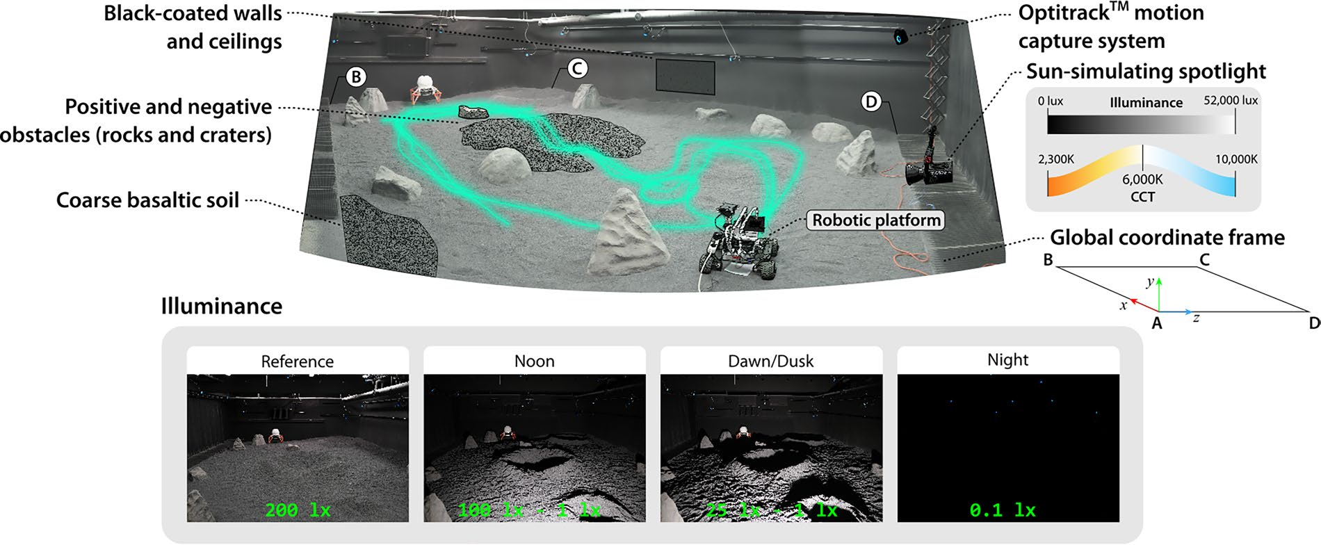
Source: [1]. CC BY 4.0.
LunaLab is an indoor lunar analogue built to reproduce light, not soil. Its design case is the high-latitude lunar visual environment: a sun a few degrees above the horizon, almost no atmospheric scattering, and a scene dominated by long moving shadows. The operators chose coarse basaltic gravel over regolith simulant deliberately, on cost and health grounds, and that choice is what bought them an 11 by 8 m field instead of a small bin [2]. The field has also been reproduced as a photogrammetric digital twin inside an open-source lunar simulator, so work that starts on the physical terrain can continue in simulation without rebuilding the scene [3].
Laboratory data
Section titled “Laboratory data”| Parameter | Value |
|---|---|
| Operator | University of Luxembourg, SnT, Space Robotics group, with ispace Europe |
| Location | Esch-sur-Alzette, Luxembourg [2] |
| Commissioned | Constructed 2019 to 2020, reported October 2020. No formal date published |
| Type | Indoor analogue terrain field at 1 g, built for optical and vision-based navigation |
| Floor area | 88 m2, 11 x 8 m [1]; 77 m2, 7 x 11 m in the construction paper [2]; 6.5 x 10 m in the simulator twin [3]. The sources disagree |
| Capabilities | Terrain field, sun simulator, motion capture |
| Simulant or terrain | Coarse basaltic gravel and sand, 20 t, 0.2 to 4 mm. Not a simulant |
| Instrumentation | 12 OptiTrack PrimeX cameras at 25 Hz. No load cells described |
| Ground truth | Motion capture position and quaternion attitude at 25 Hz |
| Fidelity limits | Grain size 0.2 to 4 mm against 40 to 130 um lunar; no opposition effect [1] |
| Access | Not published. The dataset is public on Zenodo, code on GitHub |
| Cited by | None. Published users are fictionlab Leo rovers [4] |
Capabilities
Section titled “Capabilities”Terrain field
Section titled “Terrain field”| Parameter | Value |
|---|---|
| Working volume | 11 x 8 m; 7 x 11 m in the construction paper [2]. Bed depth not published |
| Test article limits | Articles run are Leo rovers, about 359 x 296 mm, masts to 550 mm |
| Vacuum | Not applicable. Ambient pressure |
| Temperature | Not applicable. No thermal capability |
| Illumination | See sun simulator |
| Simulant or terrain | Basaltic gravel and sand, 20 t, 0.2 to 4 mm, with placed rocks and shaped craters [2] |
| Gravity offload | Not applicable |
| Instrumentation | Ceiling OptiTrack; walls and ceiling painted black |
A rectangular field of loose basaltic material with rocks and shaped craters on it, inside a room whose walls and ceiling are painted black. Every element of that is an optical decision.
The soil choice is the most consequential and the operators explain it directly. Regolith simulant was rejected because of its cost and because its fine fraction is a carcinogenic inhalation hazard, and rejecting it is what allowed the field to be built at 20 t and tens of square meters rather than as a small enclosed bin [2]. The material is chosen for its reflectance and its ability to hold a shaped crater rim, not for its mechanical behavior under a wheel: basalt sand at 0.2 to 1 mm plus gravel at 2 to 5 mm, and a separate ispace lunar yard of 8 by 8 m holding 3 t was built alongside it [2]. Bed depth and relative density control are not published.
Black paint on the walls and ceiling is the shadow-contrast measure. The operators record it as a mitigation rather than a solution: lunar shadows are darker than the room can produce, and the paint reduces but does not remove the bounce that fills them.
Sun simulator
Section titled “Sun simulator”| Parameter | Value |
|---|---|
| Working volume | One movable head on the short side of the field |
| Illumination | Aputure LightStorm 600c Pro, 600 W, 69 to 51,100 lux, 2300 to 10,000 K |
| Slope | Solar elevation 8 degrees at 80 cm lamp height, 4 degrees at 40 cm |
| Instrumentation | Lamp position adjustable vertically and horizontally |
The lamp is a single source and its height is the control variable. At 80 cm above the floor it subtends 8 degrees at the field center and at 40 cm it subtends 4 degrees, which brackets the elevations a polar site sees across a lunar day [1]. Color temperature is set to 6000 K to approximate the solar spectrum. Four standard cases were defined for the published dataset: a reference case at 200 lux, a noon case at 100 down to 1 lux, a dawn and dusk case at 25 down to 1 lux, and a night case at 0.1 lux [1].
The earlier configuration used a 2000 W and a 1000 W tungsten bulb with a focusing lens, reaching about 100,000 lux at 1 m, run in flood mode with barn doors [2].
Motion capture
Section titled “Motion capture”| Parameter | Value |
|---|---|
| Working volume | Ceiling mounted over the field |
| Instrumentation | 12 OptiTrack PrimeX cameras, logging at 25 Hz |
| Illumination | Emits infrared tracking light and status LED rings into the scene |
Accuracy is stated by the operators only as sub-millimeter, with no numeric figure published [1]. A validation of the same class of array, a 16-camera OptiTrack rig at NASA Glenn’s SLOPE facility, found the software’s self-reported mean error of 0.17 mm was honest as an aggregate but understated error in regions where test hardware occluded cameras, and that more cameras were needed to close the occluded regions [10]; an unvalidated sub-millimeter claim here should be read the same way. The system pollutes the scene it measures, which is treated below as a fidelity limit rather than as an instrumentation note.
Instrumentation
Section titled “Instrumentation”Ground truth is the twelve-camera ceiling-mounted OptiTrack rig described above.
The instrumentation that matters here is the payload rather than the facility. The published campaign carried a monochrome camera, a stereo-inertial sensor and, for the first time in a planetary exploration setting, a single-photon avalanche diode camera, alongside wheel odometry and an inertial unit [1]. A single-photon detector is the natural instrument for a scene whose interesting cases are at 1 lux and below, and the facility is built to produce those cases.
What it does not reproduce
Section titled “What it does not reproduce”Regolith. Grain size is 0.2 to 4 mm against 40 to 130 um for lunar regolith, a difference of one to two orders of magnitude [1]. The real material also carries bulk density rising from about 1.30 g/cm3 at the surface toward 1.92 g/cm3 by 60 cm depth [6] and shear strength that climbs with it, above 2 kPa at 1 m depth, none of which loose basalt gravel at 1 g is built to match [9]. Nothing measured here about wheel sinkage, slip, dust lofting or adhesion transfers to the Moon, and the facility does not claim it does. The operators’ rejection of simulant is itself consistent with the wider record: NASA’s own simulant-scoring work finds that even purpose-built lunar simulants rarely exceed a composition figure of merit around 0.6 against an Apollo reference, because none but the NU-LHT series contain anything standing in for lunar agglutinates [7][8], so a graded basalt that makes no claim to compositional fidelity is not obviously worse placed than a simulant that claims it and falls short. The same workshop that set NASA’s simulant framework also tabulated the geotechnical envelope a simulant is expected to reproduce, cohesion 0.1 to 1 kPa and friction angle 30 to 50 degrees among the targets [8], a bar the facility’s coarse gravel does not attempt to clear.
The opposition effect. The operators state plainly that the backscatter surge lunar regolith shows near zero phase angle cannot be reproduced in the facility at all [1]. The opposition surge is a first-order term in lunar photometry, so a photometrically calibrated perception algorithm cannot be validated against it here.
Regolith reflectance. The soil is less reflective than real regolith, which the operators offer as a worst-case optical scenario rather than as a match.
Collimated sunlight. The lamp is close to the field relative to the field’s size, so illuminance falls off as the inverse square across it, producing uneven illumination and inconsistent exposure along a long trajectory [1]. Real solar illumination is effectively collimated and uniform across a rover’s traverse.
A dark scene that is only dark. The measurement system contaminates the measurement. Status LED rings and the infrared illumination the motion capture cameras emit act as secondary light sources, producing faint glows, ghosting and lens flares in the dark cases, an effect the operators describe as overlooked and unavoidable. Any perception result at 0.1 lux [1] carries it.
Lunar shadow contrast and full solar illuminance. The lamps reach about 100,000 lux in the earlier configuration against a lunar solar constant equivalent of about 135,000 lux, and shadows are not as black as lunar shadows even with black walls and ceiling [2].
Dust discipline. The fine material still lifts and has to be allowed to settle between runs, and it ingresses into mechanisms [2].
Campaigns run there
Section titled “Campaigns run there”SPICE-HL3 dataset, recorded 2024 and published 2026. Two fictionlab Leo rovers, 88 sequences and 1.3 million images across seven trajectories and four illumination conditions, at 5 cm/s and 50 cm/s, with and without headlights [1]. Measured: stereo RGB-inertial, monocular monochrome and single-photon imagery with wheel odometry and inertial data, all against motion capture ground truth. The single-photon camera produced tighter and more stable image quality distributions clustered around the mean, while the conventional cameras reached lower absolute minimum and mean quality scores because of their higher resolution; visual SLAM pipelines were run to their failure points under the dark cases. The dataset is the facility’s principal published output.
Facility construction, 2019 to 2020. The construction paper is itself a lessons-learned report on lighting, surface material and shadow contrast for two indoor lunar analogues, the LunaLab and the adjacent ispace yard [2].
Terrain-induced vibration prediction. LunaLab is one of three test environments, along with a lakeshore and a disused mine, used to validate a lightweight method that predicts rover vibration from LiDAR terrain roughness corrected with IMU data on a Leo Rover [4].
Downstream simulation. The photogrammetric digital twin of LunaLab is one of the environments distributed with an open-source lunar robotics simulator, and a separate terramechanics campaign on a 20 m sand bed has since fitted slip and sinkage models for that same simulator, an effective-radius correction for grousered wheels among the results [3][5].
Where it sits among analogue facilities
Section titled “Where it sits among analogue facilities”Lunar analogue facilities divide into four families by what they reproduce, and no facility reproduces all four. All of the facilities below are ground installations at 1 g, and none has flown [2][13].
Optical indoor yards. LunaLab belongs here. The construction paper surveys its peers: the NASA Ames Lunar Testbed at 4 by 4 m and 0.5 m deep in JSC-1A with twelve lights, the NASA KSC regolith laboratory at 8 by 8 m with Black Point-1 to 1.5 m depth, the JAXA Sagamihara sandbox at 22.6 by 17.7 m with 425 t of silica sand, and a Korean chamber at 4.0 by 3.8 m with 25 t of soil under vacuum from minus 190 to 150 C [2]. The pattern is a trade between area and fidelity: the large fields use common sand or basalt, and the small ones use simulant. An earlier indoor example is the 4 by 12 m sand arena with four ceiling-mounted tracking cameras that JPL used to evaluate Mars Pathfinder microrover navigation over more than 85 trials, with rocks placed from an exponential size-frequency model [14]. Ceiling tracking cameras for rover ground truth are therefore not new to LunaLab.
Large outdoor and mixed yards. The DLR Moon-Mars site covers 1500 m2 with a 10 m wide, 2 m deep crater, a 4 m concrete lava tube and a 16 by 2 m sand patch for drilling, and has run autonomous navigation, sampling and rough-terrain demonstrations with the LRU1, LRU2 and Scout robots [12]. The JSC Rock Yard has a 40 by 40 m Lunar Yard with three craters, and Chamber B at 7.6 m diameter adds vacuum and a monorail weight-relief system for one suited crew member [13]. The PISCES site at Mauna Kea is described as a simulated lunar outpost, though its published material is a plan with design-target wheel figures rather than test results [27]. These sites supply scale, slopes and weather exposure that LunaLab cannot, and give up controlled illumination.
Regolith-fidelity facilities. ESA’s LUNA facility at the European Astronaut Centre spans 1000 m2, of which 750 m2 is a 60 cm deep mare area holding about 20 t of EAC-1, with a Dust Chamber of fine highland simulant to 250 micrometers [11]. LunaLab holds a comparable 20 t of material by mass [2], so the two differ in what the mass is, not how much there is. Abrasivity differs across the four LUNA simulants on the Soil Abrasion Test scale, from 2 for Lumina90 to 9 for Lumina250 and 6.5 for EAC-1, so wear results do not transfer between its two testbeds [11].
Environmental chambers. Vacuum, thermal and dust-adhesion work is done in chambers, not yards. The NASA Glenn Lunar Dust Adhesion Bell Jar treats dust, vacuum, temperature, solar radiation and reduced gravity as the five factors a lunar simulation has to reproduce, and its dust activation protocol includes a 200 C bakeout, three thermal cycles to about minus 150 C and a two-stage plasma treatment [17]. The authors describe it as a design that they hope produces the right surface defects, not a validated reproduction [17]. A 150 kg Black Point-1 bin prepared for a Marshall 15 ft chamber test erupted below 2 Torr when undried, and baking at 250 F for 2 hours prevented it [16]. LunaLab has none of this capability.
Soil: what the alternatives cost
Section titled “Soil: what the alternatives cost”LunaLab’s choice of basalt over simulant is one point on a spectrum. NASA’s simulant guide scores fourteen commercial and NASA simulants against Apollo and Luna references on mineralogy, chemistry, particle size, particle shape, density, magnetic susceptibility and shear strength, and concludes that no simulant is best and none reproduces every property [15]. The same guide carries the Carrier reference strength table, with friction angle 42 degrees and cohesion 0.52 kPa over 0 to 15 cm, rising to 54 degrees and 3.0 kPa over 30 to 60 cm [15]. Simulant beds are also hard to keep repeatable: top-plate vibration raised mean shear strength of Black Point-1 only from 1.70 to about 2.3 kPa while tripling to eight times the scatter, and the most repeatable state came from snowing the simulant in uncompacted [16]. A discrete element model of a Mars Exploration Rover wheel in JSC-1A was validated against one Cornell wheel-digging test at a single wheel speed, and its bulk density of 1820 kg/m3 did not match the physical bed [29]. Those findings are for simulant. A basalt field like LunaLab’s has no published equivalent characterization, so its bed state per campaign is unrecorded.
Perception work this kind of facility supports
Section titled “Perception work this kind of facility supports”The facility exists to test camera-based navigation under lunar lighting. The families of method and their status:
Field-demonstrated, not flown. ShadowNav localizes a rover in total darkness from a stereo camera and an onboard flood light, matching crater-rim range discontinuities to an orbital crater map with a particle filter. On Cinder Lakes crater-field data under a New Moon, final absolute error averaged 1.9 to 4.8 m with maxima under 9 m, provided odometry error stayed at or below 2 percent of distance [22]. The light placed 0.2 m below the camera was required, because in-line placement degraded stereo badly [22]. LunaLab’s night case at 0.1 lux is the indoor counterpart of that condition, though the secondary light from its motion capture system contaminates the dark cases [1].
Simulation only. A Gazebo and ROS rover simulator for the Resource Prospector reference mission found stereo visual odometry on synthetic imagery beat fused wheel and star tracker odometry for camera rotations of 50 degrees or less, and found that rover lights in permanently shadowed terrain degraded stereo point clouds because the Hapke reflectance model produces strong contrast-reducing backscatter [23]. A stereo SLAM system with DEM-derived height and surface-normal factors cut absolute trajectory error from 78.0 m to 7.71 m on one simulated 1.19 km traverse with injected pose noise, a single-run result [24]. A real-time stereo and semantic mapping pipeline built on 3D Gaussian Splatting reconstructed a 120 m traverse with 2.8 cm mean height error on synthetic south-pole renders only [25]. None of these used LunaLab imagery, and the synthetic-to-real gap they depend on is what the OmniLRS rock-segmentation results measure on LunaLab alone [3].
Illumination planning. What a rover sees depends on where it is. Of roughly 120,000 south polar sites analyzed on a 600 m radar elevation model for the worst-case lunar day, only 635 exceeded 50 percent average illumination, 67 exceeded 60 percent, one exceeded 70 percent and none exceeded 80 percent [26]. The elevation model had false high terrain near Shackleton that was removed by hand [26]. Lighting at those sites is low-angle and long-shadowed, which is the case LunaLab’s 4 and 8 degree lamp positions were built to approximate [1].
Datasets from comparable analogue sites
Section titled “Datasets from comparable analogue sites”SPICE-HL3’s authors position it against datasets that have motion but not polar lighting [1]. The Devon Island set is a 10 km stereo traverse in the Canadian High Arctic with DGPS ground truth, recorded in a single day in 2008 [18]. MADMAX holds 36 trajectories, 9.2 km combined, from eight Mars-analog sites in Morocco with RTK GNSS ground truth [20]. BASEPROD is 1.7 km over 24 teleoperated traverses in a Spanish semi-desert with the half-scale MaRTA rover, including six-wheel force-torque data [19]. CAVERS adds 24 SLAM sequences in a karstic cave under torch, cave-light and total-darkness conditions, with 120 Hz OptiTrack ground truth [21]. The ESA and DLR Etna campaign applied a lunar-style operations concept at a high-fidelity field site [28]. Cooperative visual odometry has been evaluated on the Morocco data by splitting one single-agent trajectory into two assumed robots, so no multi-robot analogue dataset is cited here [30]. Outdoor datasets bring natural terrain and real soil and give up controlled, repeatable illumination and sub-millimeter ground truth. LunaLab and CAVERS sit at the other end: motion capture truth and repeatable lighting, with a room in place of a landscape.
What is not established
Section titled “What is not established”The construction paper reports no photometric calibration, no measured bidirectional reflectance and no soil mechanical properties for the facility, and its optical fidelity claim rests on visual comparison with Apollo imagery [2]. The dimensions disagree across the sources (7 by 11 m, 11 by 8 m and 6.5 by 10 m) [1][2][3]. The motion capture accuracy is stated as sub-millimeter without a published figure [1]. Time synchronization of the dataset is at millisecond accuracy by NTP, which the authors call marginal for the 50 cm/s sequences [1].
The opposition surge, a first-order term in lunar photometry well documented in lunar photometry, is not reproducible in the facility [1]. No published work validates LunaLab image statistics against real lunar surface imagery at matched illumination. The simulator results show models trained on pathtraced LunaLab data reach 59.3 AP against 64.7 for real data, but best AP on 74 Apollo 17 images is 11.4, so transfer to real Moon imagery is not shown [3]. No terramechanics result from the field transfers to the Moon [1][2]. The first-use single-photon camera result is one dataset’s quality-score distributions, not a navigation accuracy result [1].
References
- Rodríguez-Martínez, D., van der Meer, D., Song, J., Bera, A., Pérez-del-Pulgar, C. J. and Olivares-Mendez, M. A. (2026). SPICE-HL3: Single-Photon, Inertial, and Stereo Camera Dataset for Exploration of High-Latitude Lunar Landscapes
. Scientific Data. Source
BibTeX
@article{rodriguezmartinez2026spice, title = {{SPICE-HL3}: Single-Photon, Inertial, and Stereo Camera Dataset for Exploration of High-Latitude Lunar Landscapes}, author = {Rodríguez-Martínez, David and van der Meer, Dave and Song, Junlin and Bera, Abhishek and Pérez-del-Pulgar, Carlos J. and Olivares-Mendez, Miguel Angel}, journal = {Scientific Data}, volume = {13}, pages = {374}, year = {2026}, doi = {10.1038/s41597-026-06668-8}, abstract = {Abstract Exploring high-latitude lunar regions presents a challenging visual environment for robots. The low sunlight elevation angle and minimal light scattering result in a visual field dominated by a strong contrast featuring long, dynamic shadows. Reproducing these conditions on Earth requires sophisticated simulators and specialized facilities. We introduce a unique dataset recorded at the LunaLab from the SnT - University of Luxembourg, an indoor test facility designed to replicate the optical characteristics of multiple lunar latitudes. Our dataset includes images, inertial measurements, and wheel odometry data from robots navigating different trajectories under multiple illumination scenarios, simulating high-latitude lunar conditions from dawn to nighttime with and without the aid of headlights, resulting in 88 distinct sequences containing a total of 1.3 M images. Data was captured using a stereo RGB-inertial sensor, a monocular monochrome camera, and, for the first time, a novel single-photon avalanche diode (SPAD) camera. We recorded both static and dynamic image sequences, with robots navigating at slow (5 cm/s) and fast (50 cm/s) speeds. All data is calibrated, synchronized, and timestamped, providing a valuable resource for validating perception tasks from vision-based autonomous navigation to scientific imaging for future lunar missions targeting high-latitude regions or those intended for robots operating across perceptually degraded environments.} } - Ludivig, P., Calzada-Diaz, A., Olivares Mendez, M. A., Voos, H. and Lamamy, J. (2020). Building a Piece of the Moon: Construction of Two Indoor Lunar Analogue Environments
. International Astronautical Congress, IAC-20-A3.2B.3. Source
BibTeX
@inproceedings{ludivig2020building, title = {Building a Piece of the {Moon}: Construction of Two Indoor Lunar Analogue Environments}, author = {Ludivig, Philippe and Calzada-Diaz, Abigail and Olivares Mendez, Miguel Angel and Voos, Holger and Lamamy, Julien}, booktitle = {International Astronautical Congress}, number = {IAC-20-A3.2B.3}, organization = {International Astronautical Federation}, year = {2020}, url = {https://orbilu.uni.lu/handle/10993/45539} } - Richard, A., Kamohara, J., Uno, K., Santra, S., van der Meer, D., Olivares-Mendez, M. and Yoshida, K. (2024). OmniLRS: A Photorealistic Simulator for Lunar Robotics
. IEEE International Conference on Robotics and Automation. Source
BibTeX
@inproceedings{richard2024omnilrs, title = {OmniLRS: A Photorealistic Simulator for Lunar Robotics}, author = {Richard, Antoine and Kamohara, Junnosuke and Uno, Kentaro and Santra, Shreya and van der Meer, Dave and Olivares-Mendez, Miguel and Yoshida, Kazuya}, booktitle = {IEEE International Conference on Robotics and Automation}, pages = {16901-16907}, year = {2024}, doi = {10.1109/icra57147.2024.10610026}, abstract = {Developing algorithms for extra-terrestrial robotic exploration has always been challenging. Along with the complexity associated with these environments, one of the main issues remains the evaluation of said algorithms. With the regained interest in lunar exploration, there is also a demand for quality simulators that will enable the development of lunar robots. In this paper, we propose Omniverse Lunar Robotic-Sim (OmniLRS) that is a photorealistic Lunar simulator based on Nvidia’s robotic simulator. This simulation provides fast procedural environment generation, multi-robot capabilities, along with synthetic data pipeline for machine-learning applications. It comes with ROS1 and ROS2 bindings to control not only the robots, but also the environments. This work also performs sim-to-real rock instance segmentation to show the effectiveness of our simulator for image-based perception. Trained on our synthetic data, a yolov8 model achieves performance close to a model trained on real-world data, with 5% performance gap. When finetuned with real data, the model achieves 14% higher average precision than the model trained on real-world data, demonstrating our simulator’s photorealism. The code is fully open-source, accessible here: https://github.com/AntoineRichard/OmniLRS, and comes with demonstrations.} } - Garcia, G. M., Aravecchia, S. and Olivares-Mendez, M. A. (2026). RoughSense: Lightweight Terrain-Induced Rover Vibration Prediction Using Point Clouds and IMU Feedback. arxiv.org/abs/2609.03720v1
BibTeX
@misc{garcia2026roughsense, title = {RoughSense: Lightweight Terrain-Induced Rover Vibration Prediction Using Point Clouds and IMU Feedback}, author = {Garcia, Gabriel Manuel and Aravecchia, Stephanie and Olivares-Mendez, Miguel Angel}, year = {2026}, url = {https://arxiv.org/abs/2609.03720v1} } - Kern, J. M., Hurrell, J. M., Santra, S., Takehana, K., Uno, K. and Yoshida, K. (2025). Data-Driven Terramechanics Approach Towards a Realistic Real-Time Simulator for Lunar Rovers
. arXiv preprint. Source
BibTeX
@article{kern2026data, title = {Data-Driven Terramechanics Approach Towards a Realistic Real-Time Simulator for Lunar Rovers}, author = {Kern, Jakob M. and Hurrell, James M. and Santra, Shreya and Takehana, Keisuke and Uno, Kentaro and Yoshida, Kazuya}, journal = {arXiv preprint}, pages = {662-668}, year = {2025}, doi = {10.1109/isparo66239.2025.11436587}, abstract = {High-fidelity simulators for the lunar surface provide a digital environment for extensive testing of rover operations and mission planning. However, current simulators focus on either visual realism or physical accuracy, which limits their capability to replicate lunar conditions comprehensively. This work addresses that gap by combining high visual fidelity with realistic terrain interaction for a realistic representation of rovers on the lunar surface. Because direct simulation of wheel-soil interactions is computationally expensive, a data-driven approach was adopted, using regression models for slip and sinkage from data collected in both full-rover and single-wheel experiments and simulations. The resulting regression-based terramechanics model accurately reproduced steady-state and dynamic slip, as well as sinkage behavior, on flat terrain and slopes up to 20°, with validation against field test results. Additionally, improvements were made to enhance the realism of terrain deformation and wheel trace visualization. This method supports real-time applications that require physically plausible terrain response alongside high visual fidelity.} } - Heiken, G. H., Vaniman, D. T. and French, B. M. (1991). Lunar Sourcebook: A User's Guide to the Moon
. Endeavour. Source
BibTeX
@book{heiken1991lunar, title = {Lunar Sourcebook: A User's Guide to the Moon}, author = {Heiken, Grant H. and Vaniman, David T. and French, Bevan M.}, journal = {Endeavour}, volume = {16}, pages = {96}, publisher = {Cambridge University Press}, year = {1991}, doi = {10.1016/0160-9327(92)90014-g} } - Schrader, C. M., Rickman, D. L., McLemore, C. A. and Fikes, J. C. (2010). Lunar Regolith Simulant User's Guide
. NASA Marshall Space Flight Center, NASA/TM-2010-216446. Source
BibTeX
@techreport{schrader2010lunar, title = {Lunar Regolith Simulant User's Guide}, author = {Schrader, C. M. and Rickman, Douglas L. and McLemore, Carole A. and Fikes, John C.}, number = {NASA/TM-2010-216446}, institution = {NASA Marshall Space Flight Center}, year = {2010}, url = {https://ntrs.nasa.gov/citations/20100038451}, abstract = {Based on primary characteristics, currently or recently available lunar regolith simulants are discussed from the perspective of potential experimental uses. The characteristics used are inherent properties of the material rather than their responses to behavioral (geomechanical, physiochemical, etc.) tests. We define these inherent or primary properties to be particle composition, particle size distribution, particle shape distribution, and bulk density. Comparable information about lunar materials is also provided. It is strongly emphasized that anyone considering either choosing or using a simulant should contact one of the members of the simulant program listed at the end of this document.} } - Sibille, L., Carpenter, P., Schlagheck, R. and French, R. A. (2006). Lunar Regolith Simulant Materials: Recommendations for Standardization, Production, and Usage
. NASA Marshall Space Flight Center, NASA/TP-2006-214605. Source
BibTeX
@techreport{sibille2006development, title = {Lunar Regolith Simulant Materials: Recommendations for Standardization, Production, and Usage}, author = {Sibille, Laurent and Carpenter, Paul and Schlagheck, R. and French, R. A.}, number = {NASA/TP-2006-214605}, institution = {NASA Marshall Space Flight Center}, type = {NASA Technical Publication}, year = {2006}, url = {https://ntrs.nasa.gov/citations/20060051776}, abstract = {Experience gained during the Apollo program demonstrated the need for extensive testing of surface systems in relevant environments, including regolith materials similar to those encountered on the lunar surface. As NASA embarks on a return to the Moon, it is clear that the current lunar sample inventory is not only insufficient to support lunar surface technology and system development, but its scientific value is too great to be consumed by destructive studies. Every effort must be made to utilize standard simulant materials, which will allow developers to reduce the cost, development, and operational risks to surface systems. The Lunar Regolith Simulant Materials Workshop held in Huntsville, AL, on January 24 26, 2005, identified the need for widely accepted standard reference lunar simulant materials to perform research and development of technologies required for lunar operations. The workshop also established a need for a common, traceable, and repeatable process regarding the standardization, characterization, and distribution of lunar simulants. This document presents recommendations for the standardization, production and usage of lunar regolith simulant materials.} } - Connolly, J. F. and Carrier, W. D. (2023). An Engineering Guide to Lunar Geotechnical Properties
. IEEE Aerospace Conference. Source
BibTeX
@inproceedings{connolly2023engineering, title = {An Engineering Guide to Lunar Geotechnical Properties}, author = {Connolly, John F. and Carrier, W. David}, booktitle = {IEEE Aerospace Conference}, pages = {1-9}, address = {Big Sky, Montana}, year = {2023}, doi = {10.1109/aero55745.2023.10115961}, abstract = {The renewed interest in returning human and robotic explorers to the lunar surface has identified a need for a renewed understanding of lunar geotechnical properties related to landing, exploration, excavation, and construction activities on the lunar surface. This paper summarizes measurements conducted during US and Russian/Soviet landed missions as well as experiments performed on returned samples to establish fundamental geotechnical properties such as particle size distribution, particle shape, bulk density, shear strength, cohesion and bearing strength. While many of these properties are well known, how they vary with increased lunar soil depth is less understood, and those properties that vary significantly as a function of depth are explored in additional detail. Selected examples discuss mechanical excavation forces, rocket exhaust erosion forces, and the preparation of launch/landing pad surfaces, with the goal of a better understanding of lunar soil geotechnical properties that apply to large-scale exploration of the lunar surface and dictate the design of future exploration systems.} } - Schepelmann, A. and Gerdts, S. (2022). Characterization of Infrared Optical Motion Tracking System in NASA's Simulated Lunar Operations (SLOPE) Laboratory
. NASA, NASA/TM-20220005304. Source
BibTeX
@techreport{schepelmann2022characterization, title = {Characterization of Infrared Optical Motion Tracking System in NASA's Simulated Lunar Operations (SLOPE) Laboratory}, author = {Schepelmann, Alexander and Gerdts, Stephen}, number = {NASA/TM-20220005304}, institution = {NASA}, year = {2022}, url = {https://ntrs.nasa.gov/citations/20220005304}, abstract = {This work characterizes the accuracy of a 16 camera OptiTrack motion tracking system installed in NASA Glenn Research Center's Simulated Lunar Operations (SLOPE) laboratory. The position of a rigid body mounted on a motorized linear stage is compared to its position reported by the motion tracking system as it travels through the facility's 777m$^3$ capture volume of interest. Experiments show that the mean error reported by the motion tracking system for the aggregate capture volume is in-line with independent measurements collected using the motion stage. Error within regions of the capture volume exceed the mean error reported by the motion tracking system, likely due to occlusion, and suggests that additional cameras should be used to increase measurement accuracy in these regions. Overall, results show that error values reported by the motion tracking system are representative of the measurement error in a collected data set and validates the system's use for characterizing the mobility and tractive performance of robots, rovers, and other vehicles for planetary exploration.} } - Zemeny, A., Sardisco, L., Quinteros, S., Mikesell, T. D., Pirrie, D., Rose, L., Cowley, A. and Manick, K. (2024). The LUNA Analog Facility testbeds (ESA, EAC): contemporary characterization work of highland and mare lunar regolith simulants
. Frontiers in Space Technologies. Source
BibTeX
@article{zemeny2024luna, title = {The {LUNA} Analog Facility testbeds ({ESA}, {EAC}): contemporary characterization work of highland and mare lunar regolith simulants}, author = {Zemeny, Aliz and Sardisco, Lorenzo and Quinteros, Susana and Mikesell, T. Dylan and Pirrie, Duncan and Rose, Laura and Cowley, Aidan and Manick, Kaushik}, journal = {Frontiers in Space Technologies}, volume = {5}, pages = {1510635}, year = {2024}, doi = {10.3389/frspt.2024.1510635}, abstract = {The Luna Analog Facility, a joint ESA-DLR endeavour, consists of three components and spans an area of 1,000 m 2 , providing testbeds of simulated lunar environments. The main sections within the facility are a large area filled with lunar mare regolith simulant resembling mare regions and a smaller, individual “Dust Chamber”. The latter replicates highland conditions and contains approximately 20 tons of material, specifically simulating the fine-particle lunar regolith portion up to 250 µm. The Dust Chamber serves as a platform for testing various technologies, such as mechanical tools, robotic operations, in-situ resource utilization activities, and astronaut attire, as well as different procedures including rover and astronaut tasks. This work represents the geotechnical, geochemical and mineralogical characterization of the Lumina Sustainable Materials Ltd. 2023 batch highland simulants, from which Lunar250 is intended for use in the Luna Dust Chamber. Additionally, this work provides new results for ESA’s mare simulant, EAC-1. We provide data on particle size distribution, particle shape, abrasivity, density, water content, major and trace element geochemistry and modal mineralogy. As the simulants in the Luna Facility will be constantly overseen, this work organized by the Vulcan Facility (ESA) intends to support the monitoring of the geotechnical property variations of the simulants over time. Ultimately, we analysed several properties with different tools to emphasize how different methods and instruments affect the variability and reliability of the results.} } - Görner, M., Cebulsky, J., Dömel, A., Durner, M., Giubilato, R., Kuhne, M., Müller, M. G., Lakatos, K., Lehner, P., Lichtenheldt, R., Rebele, B., Roser, M., Sakagami, R., Scheeler, Y., Schuster, M. J., Schütt, M., Stürzl, W., Vayugundla, M. and Wedler, A. (2024). The DLR Moon-Mars Test Site for Robotic Planetary Exploration
. International Conference on Space Robotics. Source
BibTeX
@inproceedings{goerner2024dlr, title = {The DLR Moon-Mars Test Site for Robotic Planetary Exploration}, author = {Görner, Martin and Cebulsky, Jennifer and Dömel, Andreas and Durner, Maximilian and Giubilato, Riccardo and Kuhne, Moritz and Müller, Marcus G. and Lakatos, Kristin and Lehner, Peter and Lichtenheldt, Roy and Rebele, Bernhard and Roser, Mattias and Sakagami, Ryo and Scheeler, Yunis and Schuster, Martin J. and Schütt, Manuel and Stürzl, Wolfgang and Vayugundla, Mallikarjuna and Wedler, Armin}, booktitle = {International Conference on Space Robotics}, pages = {245-252}, institution = {DLR Institute of Robotics and Mechatronics}, year = {2024}, doi = {10.1109/isparo60631.2024.10687411}, abstract = {Building robots for planetary exploration missions requires intensive testing throughout all phases of the design process. Especially, during hard- and software development as well as mission training the process benefits of easy-to-access test sites that offer realistic conditions. For this purpose we have built the 1500 m2DLR Moon-Mars test site in Oberpfaffenhofen, Germany. The facility provides a large variety of geological formations and ground substrates on a compact terrain as well as a rich set of power and network connections. As a unique feature of the outdoor test site, we prepared a dedicated link to the German Space Operations Center that enables telerobotic experiments from ISS. Furthermore, we provide an optical tracking system for ground truth measurement and control. We describe the design and construction process of the test site and present an overview of its features. Three experiments with our robots LRU1, LRU2 and the Scout rover regarding autonomous navigation and mapping, autonomous manipulation and sampling as well as advanced mobility tests demonstrate the usage of the test site.} } - NASA Johnson Space Center. (2024). JSC Analogs and Mockups. nasa.gov/reference/jsc-analogs-mockups
BibTeX
@misc{nasajscanalogs, title = {JSC Analogs and Mockups}, author = {{NASA Johnson Space Center}}, organization = {nasa.gov}, year = {2024}, url = {https://www.nasa.gov/reference/jsc-analogs-mockups/} } - Matthies, L., Gat, E., Harrison, R., Wilcox, B., Volpe, R. and Litwin, T. (1995). Mars Microrover Navigation: Performance Evaluation and Enhancement
. Autonomous Robots, 4. Source
BibTeX
@article{matthies1995mars, title = {Mars Microrover Navigation: Performance Evaluation and Enhancement}, author = {Matthies, Larry and Gat, Erann and Harrison, Reid and Wilcox, Brian and Volpe, Richard and Litwin, Todd}, journal = {Autonomous Robots}, volume = {2}, number = {4}, pages = {291--311}, year = {1995}, doi = {10.1007/bf00710796} } - Slabic, A., Gruener, J. E., Kovtun, R. N., Rickman, D. L., Sibille, L., Oravec, H. A., Edmunson, J. and Keprta, S. (2024). Lunar Regolith Simulant User's Guide, Revision A
. NASA, NASA/TM-20240011783. Source
BibTeX
@techreport{slabic2024lunar, title = {Lunar Regolith Simulant User's Guide, Revision A}, author = {Slabic, Ane and Gruener, John E. and Kovtun, Rostislav N. and Rickman, Douglas L. and Sibille, Laurent and Oravec, Heather A. and Edmunson, Jennifer and Keprta, Sean}, number = {NASA/TM-20240011783}, institution = {NASA}, year = {2024}, url = {https://ntrs.nasa.gov/citations/20240011783}, abstract = {This guide is titled Lunar Regolith Simulant User's Guide, Rev A, and two points need to be made about the title. First, is the use of the term "regolith". During the Apollo Program, the term "soil" was used for taking a sample of the loose material on the surface, and then cataloging that sample in the lunar curation database as a "soil sample". By the 1980s, the term "regolith" gained favor by lunar scientists. In the Lunar Sourcebook (Heiken et al., 1991), regolith is defined as "a general term for the layer or mantle of fragmental and unconsolidated rock material, whether residual or transported and of highly varied character, that nearly everywhere forms the surface of the land and overlies or covers bedrock". Regolith is a terrestrial term that seems to go back to 1897, according to a recent paper by Huggett (2023). Huggett summed up his paper by writing, "soil and regolith are one in the same". "Regolith" will mostly be used throughout this guide, as it tends to separate in one's mind the unique nature of the Moon's surface when compared to the inherent bias humans have in their mind when they hear and use the word "soil". When referring to Apollo samples, "soil" is used for historical context and in some places the simple term "lunar simulant" is also used. Secondly, Rev A is used in the title because NASA released its first Lunar Regolith Simulant User's Guide in 2010, near the end of NASA's Constellation Program (Schrader et al., 2010). This guide follows in the pattern of that first guide and will be updated on a periodic basis as new simulants are created, characterized and used, and as new information emerges about the Moon's regolith due to new lunar exploration missions, both robotic and human.} } - Mantovani, J., Langton, A., Kemmerer, B., Atkins, A. and Batcheldor, D. (2022). Regolith Simulant Preparation and Geotechnical Characterization for Plume Surface Interaction Testing
. NASA, 20220013110. Source
BibTeX
@techreport{mantovani2022regolith, title = {Regolith Simulant Preparation and Geotechnical Characterization for Plume Surface Interaction Testing}, author = {Mantovani, James and Langton, Austin and Kemmerer, Beverly and Atkins, Austin and Batcheldor, Daniel}, number = {20220013110}, institution = {NASA}, year = {2022}, url = {https://ntrs.nasa.gov/citations/20220013110}, abstract = {Descent engine plumes interact with the lunar surface and accelerate regolith particles to potentially high velocities. These ejecta create risks to surface assets that have yet to be fully assessed. To better understand these risks, plume surface interactions can be simulated on the ground by firing a test engine plume into a bin of lunar regolith simulant under vacuum conditions. The dynamics of the resultant ejecta can then be recorded. In this technical memorandum we discuss the processes used in preparing a 150 kg bin of lunar regolith simulant for plume surface interaction ground tests under vacuum conditions for the NASA STMD Plume Surface Interaction project. We present our approach to mitigating regolith simulant eruptions during pump-down, the methods used to fill and reset the regolith simulant bin for each test, and the techniques used to characterize the consistency of regolith simulant geotechnical properties before each new firing. The challenges of preparing a regolith simulant test bin below an ambient pressure of one atmosphere, particularly on the large scale, could largely be overcome with a system that could fill the test bin with simulant inside the chamber and under vacuum conditions.} } - Gaier, J. R. and Sechkar, E. A. (2007). Lunar Simulation in the Lunar Dust Adhesion Bell Jar
. AIAA Aerospace Sciences Meeting, NASA/TM-2007-214704. Source
BibTeX
@inproceedings{gaier2007lunar, title = {Lunar Simulation in the Lunar Dust Adhesion Bell Jar}, author = {Gaier, James R. and Sechkar, Edward A.}, booktitle = {AIAA Aerospace Sciences Meeting}, number = {NASA/TM-2007-214704}, institution = {NASA}, year = {2007}, doi = {10.2514/6.2007-963}, abstract = {The Lunar Dust Adhesion Bell Jar has been assembled at the NASA Glenn Research Center to provide a high fidelity lunar simulation facility to test the interactions of lunar dust and lunar dust simulant with candidate aerospace materials and coatings. It has a sophisticated design which enables it to treat dust in a way that will remove adsorbed gases and create a chemically reactive surface. It can simulate the vacuum, thermal, and radiation environments of the Moon, including proximate areas of illuminated heat and extremely cold shadow. It is expected to be a valuable tool in the development of dust repellant and cleaning technologies for lunar surface systems.} } - Furgale, P., Carle, P., Enright, J. and Barfoot, T. D. (2012). The Devon Island rover navigation dataset
. The International Journal of Robotics Research, 6. Source
BibTeX
@article{furgale2012devon, title = {The Devon Island rover navigation dataset}, author = {Furgale, Paul and Carle, Pat and Enright, John and Barfoot, Timothy D.}, journal = {The International Journal of Robotics Research}, volume = {31}, number = {6}, pages = {707-713}, publisher = {SAGE Publications}, year = {2012}, doi = {10.1177/0278364911433135}, abstract = {In this paper we present a rover navigation dataset collected at a Mars/Moon analogue site on Devon Island, in the Canadian High Arctic. The dataset is split into two parts. The first part contains rover traverse data: stereo imagery, Sun vectors, inclinometer data, and ground-truth position information from a differential global positioning system (DGPS) collected over a 10-km traverse. The second part contains long-range localization data: 3D laser range scans, image panoramas, digital elevation models, and GPS data useful for global position estimation. All images are available in common formats and other data is presented in human-readable text files. To facilitate use of the data, Matlab parsing scripts are included.} } - Gerdes, L., Wiese, T., Castilla Arquillo, R., Bielenberg, L., Azkarate, M., Leblond, H., Wilting, F., Ortega Cortés, J., Bernal, A., Palanco, S. and Pérez del Pulgar, C. (2024). BASEPROD: The Bardenas Semi-Desert Planetary Rover Dataset
. Scientific Data. Source
BibTeX
@article{gerdes2024baseprod, title = {BASEPROD: The Bardenas Semi-Desert Planetary Rover Dataset}, author = {Gerdes, Levin and Wiese, Tim and Castilla Arquillo, Raúl and Bielenberg, Lars and Azkarate, Martin and Leblond, Hugo and Wilting, Falk and Ortega Cortés, Javier and Bernal, Adrián and Palanco, Santiago and Pérez del Pulgar, Carlos}, journal = {Scientific Data}, volume = {11}, pages = {1054}, year = {2024}, doi = {10.1038/s41597-024-03881-1}, abstract = {Abstract Dataset acquisitions devised specifically for robotic planetary exploration are key for the advancement, evaluation, and validation of novel perception, localization, and navigation methods in representative environments. Originating in the Bardenas semi-desert in July 2023, the data presented in this Data Descriptor is primarily aimed at Martian exploration and contains relevant rover sensor data from approximately 1.7km of traverses, a high-resolution 3D map of the test area, laser-induced breakdown spectroscopy recordings of rock samples along the rover path, as well as local weather data. In addition to optical cameras and inertial sensors, the rover features a thermal camera and six force-torque sensors. This setup enables, for example, the study of future localization, mapping, and navigation techniques in unstructured terrains for improved Guidance, Navigation, and Control (GNC). The main features of this dataset are the combination of scientific and engineering instrument data, as well as the inclusion of the thermal camera and force-torque sensors in particular.} } - Meyer, L., Smíšek, M., Fontan Villacampa, A., Oliva Maza, L., Medina, D., Schuster, M. J., Steidle, F., Vayugundla, M., Müller, M. G., Rebele, B., Wedler, A. and Triebel, R. (2021). The MADMAX data set for visual-inertial rover navigation on Mars
. Journal of Field Robotics, 6. Source
BibTeX
@article{meyer2021madmax, title = {The MADMAX data set for visual-inertial rover navigation on Mars}, author = {Meyer, Lukas and Smíšek, Michal and Fontan Villacampa, Alejandro and Oliva Maza, Laura and Medina, Daniel and Schuster, Martin J. and Steidle, Florian and Vayugundla, Mallikarjuna and Müller, Marcus G. and Rebele, Bernhard and Wedler, Armin and Triebel, Rudolph}, journal = {Journal of Field Robotics}, volume = {38}, number = {6}, pages = {833-853}, publisher = {Wiley}, year = {2021}, doi = {10.1002/rob.22016}, abstract = {Abstract Planetary rovers increasingly rely on vision‐based components for autonomous navigation and mapping. Developing and testing these components requires representative optical conditions, which can be achieved by either field testing at planetary analog sites on Earth or using prerecorded data sets from such locations. However, the availability of representative data is scarce and field testing in planetary analog sites requires a substantial financial investment and logistical overhead, and it entails the risk of damaging complex robotic systems. To address these issues, we use our compact human‐portable DLR Sensor Unit for Planetary Exploration Rovers (SUPER) in the Moroccan desert to show resource‐efficient field testing and make the resulting Morocco‐Acquired data set of Mars‐Analog eXploration (MADMAX) publicly accessible. The data set consists of 36 different navigation experiments, captured at eight Mars analog sites of widely varying environmental conditions. Its longest trajectory covers 1.5 km and the combined trajectory length is 9.2 km. The data set contains time‐stamped recordings from monochrome stereo cameras, a color camera, omnidirectional cameras in stereo configuration, and from an inertial measurement unit. Additionally, we provide the ground truth in position and orientation together with the associated uncertainties, obtained by a real‐time kinematic‐based algorithm that fuses the global navigation satellite system data of two body antennas. Finally, we run two state‐of‐the‐art navigation algorithms, ORB‐SLAM2 and VINS‐mono, on our data to evaluate their accuracy and to provide a baseline, which can be used as a performance reference of accuracy and robustness for other navigation algorithms. The data set can be accessed at https://rmc.dlr.de/morocco2018 .} } - Franchini, G., Rodríguez-Martínez, D., Martínez-Petersen, A., Pérez-del-Pulgar, C. J. and Chiaberge, M. (2026). CAVERS: Multimodal SLAM Data from a Natural Karstic Cave with Ground Truth Motion Capture
. IEEE Robotics and Automation Letters. Source
BibTeX
@article{franchini2026cavers, title = {CAVERS: Multimodal SLAM Data from a Natural Karstic Cave with Ground Truth Motion Capture}, author = {Franchini, Giacomo and Rodríguez-Martínez, David and Martínez-Petersen, Alfonso and Pérez-del-Pulgar, C. J. and Chiaberge, Marcello}, journal = {IEEE Robotics and Automation Letters}, volume = {11}, pages = {11514-11521}, publisher = {Institute of Electrical and Electronics Engineers (IEEE)}, year = {2026}, doi = {10.1109/lra.2026.3726391}, abstract = {Autonomous robots operating in natural karstic caves face perception and navigation challenges that are qualitatively distinct from those encountered in mines or tunnels: irregular geometry, reflective wet surfaces, near-zero ambient light, and complex branching passages. Yet publicly available datasets targeting this environment remain scarce and offer limited sensing modalities and environmental diversity. We present CAVERS, a multimodal dataset acquired in two structurally distinct rooms of Cueva de la Victoria, Málaga, Spain, containing 24 sequences with approximately 335 GB of recorded data. The sensor suite combines an Intel RealSense D435i RGB-D-I camera, an Optris PI640i near-IR thermal camera, and a Velodyne VLP-16 LiDAR, operated both handheld and mounted on a wheeled rover under full darkness and artificial illumination. For most of the sequences, mm-accurate 6-DoF ground truth pose and velocity at 120 Hz are provided by an Optitrack motion capture system installed directly inside the cave. We benchmark seven state-of-the-art SLAM and odometry algorithms spanning visual, visual-inertial, thermal-inertial, and LiDAR-based pipelines, as well as a 3D reconstruction pipeline, demonstrating the dataset's usability. The dataset and all supplementary material are publicly available at: https://github.com/spaceuma/cavers.} } - Allan, M., Wong, U., Furlong, P. M., Rogg, A., McMichael, S., Welsh, T., Chen, I., Peters, S., Gerkey, B., Quigley, M., Shirley, M., Deans, M., Cannon, H. and Fong, T. (2019). Planetary Rover Simulation for Lunar Exploration Missions
. IEEE Aerospace Conference, 20190027571. Source
BibTeX
@inproceedings{allan2019planetary, title = {Planetary Rover Simulation for Lunar Exploration Missions}, author = {Allan, Mark and Wong, Uland and Furlong, Padraig M. and Rogg, Arno and McMichael, Scott and Welsh, Terry and Chen, Ian and Peters, Steven and Gerkey, Brian and Quigley, Morgan and Shirley, Mark and Deans, Mathew and Cannon, Howard and Fong, Terry}, booktitle = {IEEE Aerospace Conference}, number = {20190027571}, pages = {1-19}, institution = {NASA}, year = {2019}, doi = {10.1109/aero.2019.8741780}, abstract = {When planning planetary rover missions it is useful to develop intuition and skills driving in, quite literally, alien environments before incurring the cost of reaching said locales. Simulators make it possible to operate in environments that have the physical characteristics of target locations without the expense and overhead of extensive physical tests. To that end, NASA Ames and Open Robotics collaborated on a Lunar rover driving simulator based on the open source Gazebo simulation platform and leveraging ROS (Robotic Operating System)components. The simulator was integrated with research and mission software for rover driving, system monitoring, and science instrument simulation to constitute an end-to-end Lunar mission simulation capability. Although we expect our simulator to be applicable to arbitrary Lunar regions, we designed to a reference mission of prospecting in polar regions. The harsh lighting and low illumination angles at the Lunar poles combine with the unique reflectance properties of Lunar regolith to present a challenging visual environment for both human and computer perception. Our simulator placed an emphasis on high fidelity visual simulation in order to produce synthetic imagery suitable for evaluating human rover drivers with navigation tasks, as well as providing test data for computer vision software development. In this paper, we describe the software used to construct the simulated Lunar environment and the components of the driving simulation. Our synthetic terrain generation software artificially increases the resolution of Lunar digital elevation maps by fractal synthesis and inserts craters and rocks based on Lunar size-frequency distribution models. We describe the necessary enhancements to import large scale, high resolution terrains into Gazebo, as well as our approach to modeling the visual environment of the Lunar surface. An overview of the mission software system is provided, along with how ROS was used to emulate flight software components that had not been developed yet. Finally, we discuss the effect of using the high-fidelity synthetic Lunar images for visual odometry. We also characterize the wheel slip model, and find some inconsistencies in the produced wheel slip behavior.} } - Dai, A., Vila, G. C. and Gao, G. (2026). Visual SLAM with DEM Anchoring for Lunar Surface Navigation
. arXiv. Source
BibTeX
@article{adam2026, title = {Visual SLAM with DEM Anchoring for Lunar Surface Navigation}, author = {Dai, Adam and Vila, Guillem Casadesus and Gao, Grace}, journal = {arXiv}, year = {2026}, doi = {10.48550/arxiv.2603.17229}, abstract = {Future lunar missions will require autonomous rovers capable of traversing tens of kilometers across challenging terrain while maintaining accurate localization and producing globally consistent maps. However, the absence of global positioning systems, extreme illumination, and low-texture regolith make long-range navigation on the Moon particularly difficult, as visual-inertial odometry pipelines accumulate drift over extended traverses. To address this challenge, we present a stereo visual simultaneous localization and mapping (SLAM) system that integrates learned feature detection and matching with global constraints from digital elevation models (DEMs). Our front-end employs learning-based feature extraction and matching to achieve robustness to illumination extremes and repetitive terrain, while the back-end incorporates DEM-derived height and surface-normal factors into a pose graph, providing absolute surface constraints that mitigate long-term drift. We validate our approach using both simulated lunar traverse data generated in Unreal Engine and real Moon/Mars analog data collected from Mt. Etna. Results demonstrate that DEM anchoring consistently reduces absolute trajectory error compared to baseline SLAM methods, lowering drift in long-range navigation even in repetitive or visually aliased terrain.} } - Vila, G. C., Dai, A. and Gao, G. (2026). Semantic Segmentation and Depth Estimation for Real-Time Lunar Surface Mapping Using 3D Gaussian Splatting
. IEEE Aerospace Conference. Source
BibTeX
@inproceedings{vila2026semantic, title = {Semantic Segmentation and Depth Estimation for Real-Time Lunar Surface Mapping Using 3D Gaussian Splatting}, author = {Vila, Guillem Casadesus and Dai, Adam and Gao, Grace}, booktitle = {IEEE Aerospace Conference}, pages = {1-14}, year = {2026}, doi = {10.1109/aero66936.2026.11519804}, abstract = {Navigation and mapping on the lunar surface require robust perception under challenging conditions, including poorly textured environments, high-contrast lighting, and limited computational resources. This paper presents a real-time mapping framework that integrates dense perception models with a 3D Gaussian Splatting (3DGS) representation. We first benchmark several models on synthetic datasets generated with the LuPNT simulator, selecting a stereo dense depth estimation model based on Gated Recurrent Units for its balance of speed and accuracy in depth estimation, and a convolutional neural network for its superior performance in detecting semantic segments. Using ground truth poses to decouple the local scene understanding from the global state estimation, our pipeline reconstructs a 120 -meter traverse with a geometric height accuracy of approximately 3 cm, outperforming a traditional point cloud baseline without LiDAR. The resulting 3DGS map enables novel view synthesis and serves as a foundation for a full SLAM system, where its capacity for joint map and pose optimization would offer significant advantages. Our results demonstrate that combining semantic segmentation and dense depth estimation with learned map representations is an effective approach for creating detailed, large-scale maps to support future lunar surface missions.} } - Fincannon, J. (2008). Lunar Polar Illumination for Power Analysis
. International Energy Conversion Engineering Conference, NASA/TM-2008-215446. Source
BibTeX
@inproceedings{fincannon2008lunar, title = {Lunar Polar Illumination for Power Analysis}, author = {Fincannon, James}, booktitle = {International Energy Conversion Engineering Conference}, number = {NASA/TM-2008-215446}, institution = {NASA Glenn Research Center}, year = {2008}, doi = {10.2514/6.2008-5631}, abstract = {Since its founding} } - Marzwell, N., Larson, W. E., Duke, M. and Schowengerdt, F. (2008). PISCES : developing new design, materials and technologies for sustained
. Earth and Science Conference. Source
BibTeX
@inproceedings{marzwell2008pisces, title = {PISCES : developing new design, materials and technologies for sustained}, author = {Marzwell, Neville and Larson, William E. and Duke, Mike and Schowengerdt, Frank}, booktitle = {Earth and Science Conference}, year = {2008}, url = {https://ntrs.nasa.gov/citations/20110013192}, abstract = {PISCES, the Pacific International Space Center for Exploration Systems. This paper describes the PISCES development plans, particularly in the areas of In-Situ Resource Utilization, Robotics and Education and Outreach.} } - Carey, W., Krueger, T., Wormnes, K., Grenouilleau, J., Ferreira, E., Nergaard, K., van der Hulst, F., den Exter, E. and Gerdes, L. (2022). METERON Analog-1: A Touch Remote
. International Astronautical Congress, IAC-22-A3.2B.4. Source
BibTeX
@inproceedings{carey2022meteron, title = {METERON Analog-1: A Touch Remote}, author = {Carey, William and Krueger, Thomas and Wormnes, Kjetil and Grenouilleau, Jessica and Ferreira, Edmundo and Nergaard, Kim and van der Hulst, Frank and den Exter, Emiel and Gerdes, Levin}, booktitle = {International Astronautical Congress}, number = {IAC-22-A3.2B.4}, year = {2022}, url = {https://elib.dlr.de/190115/} } - Knuth, M., Johnson, J. B., Hopkins, M., Sullivan, R. J. and Moore, J. (2012). Discrete element modeling of a Mars Exploration Rover wheel in granular material
. Journal of Terramechanics, 1. Source
BibTeX
@article{knuth2012discrete, title = {Discrete element modeling of a Mars Exploration Rover wheel in granular material}, author = {Knuth, M.A. and Johnson, Jerome B. and Hopkins, M.A. and Sullivan, Robert J. and Moore, J.M.}, journal = {Journal of Terramechanics}, volume = {49}, number = {1}, pages = {27-36}, publisher = {Elsevier BV}, year = {2012}, doi = {10.1016/j.jterra.2011.09.003} } - Bahraini, M. S., Zenati, A. and Aouf, N. (2021). Autonomous Cooperative Visual Navigation for Planetary Exploration Robots
. IEEE International Conference on Robotics and Automation. Source
BibTeX
@inproceedings{bahraini2021autonomous,
  title = {Autonomous Cooperative Visual Navigation for Planetary Exploration Robots},
  author = {Bahraini, Masoud S. and Zenati, Abdelhafid and Aouf, Nabil},
  booktitle = {IEEE International Conference on Robotics and Automation},
  pages = {9653-9658},
  year = {2021},
  doi = {10.1109/icra48506.2021.9561767}
}