Scarab
Program pages Carnegie Mellon Field Robotics Center: Scarab
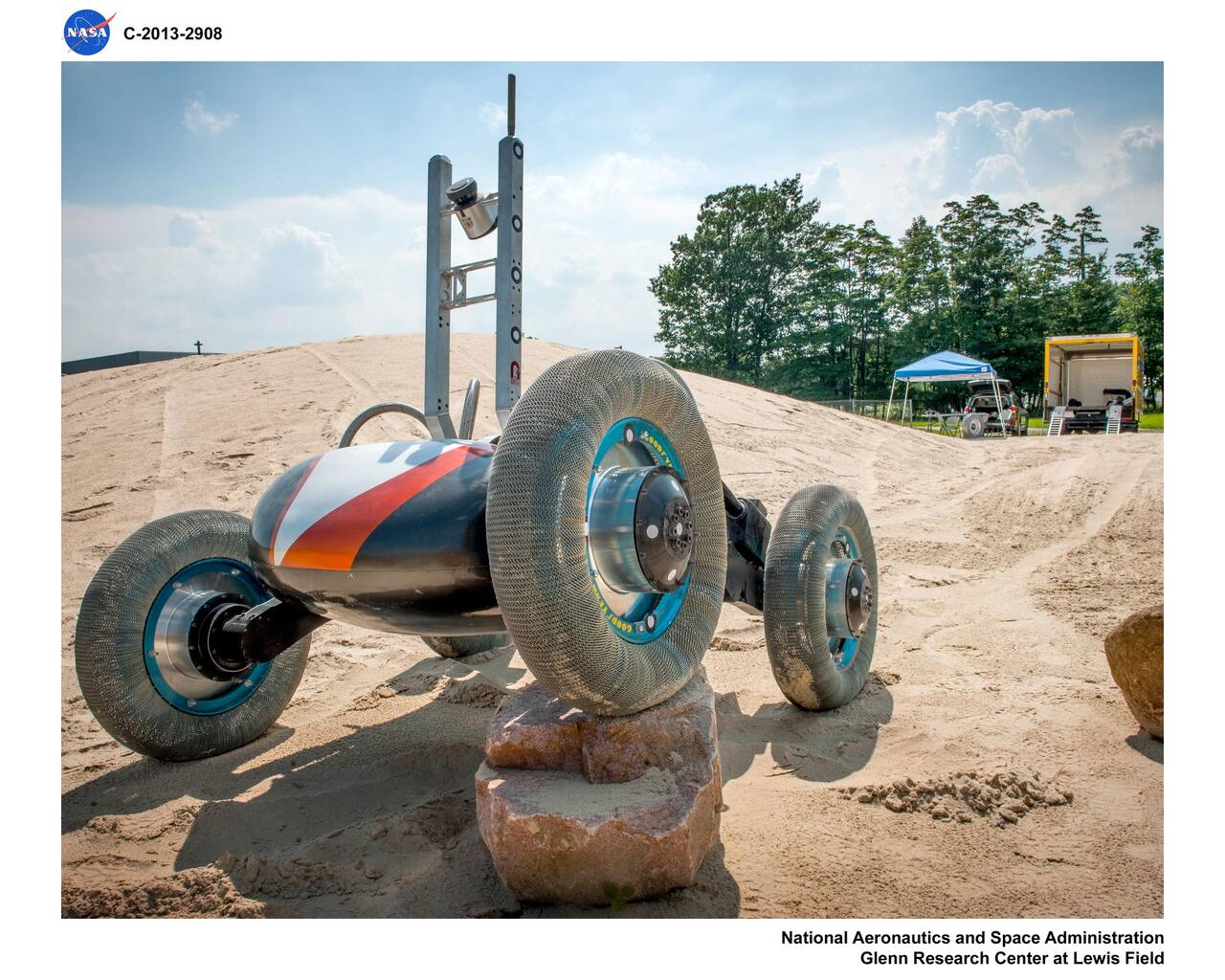 NASA. Public domain (NASA / US government work).
Scarab is a 280 kg four-wheeled prospecting rover built at Carnegie Mellon University in 2007 to carry a 1 m coring drill into permanently shadowed lunar polar craters [1], [12]. It never left Earth.
The problem
Section titled “The problem”A cold-trap prospector has to find and sample water ice and other volatiles that survive only because they are cold. The design environment for Scarab was hard vacuum, a 40 K ground and a 3 K sky, with no sunlight for power or cameras [1]. Survey compilations list the same envelope of temperature extremes, dust and regolith bearing limits for every lunar rover concept, and most of the concepts in them were design targets that were never built [11].
Three requirements follow. The vehicle must drive across unconsolidated slopes on crater walls. It must hold a stiff base for drilling, because a coring drill thrusting at 100 to 200 N or more needs weight on the ground to react it, and that requirement set Scarab’s mass [1]. It must do both without ambient light, so navigation uses active laser sensing [10].
The ground it works on is characterized poorly. The geotechnical values in the standard engineering reference come from Apollo and Luna sites near the equator [14], and the polar regolith that Scarab was built for has not been sampled in place [10].
What has flown
Section titled “What has flown”No Scarab flew, and no rover has drilled lunar polar regolith. The flown items that bear on the design are few.
Honeybee Robotics’ TRIDENT drill, a 1 m rotary-percussive design with a twenty-year lineage that includes Resource Prospector, was built in two identical flight units, one for the PRIME-1 payload of the IM-2 lander and one for VIPER [28]. VIPER was canceled before launch, so only the PRIME-1 unit was in a position to reach the Moon.
LEV-1, a JAXA hopping rover, operated on the Moon after the SLIM landing in January 2024 [22]. Its single wheel carries a 90-degree-tilted octagonal grouser chosen with a resistive-force-theory model and checked in sand and discrete element simulation before flight [22]. It is a different vehicle class from Scarab and the only flown grouser result among the works cited here.
Scarab itself is a ground prototype. The 2008 design paper reports a continuous 1 km traverse, a 50 cm trench bridge and rock obstacles of 40 to 50 cm climbed, all at Earth gravity on rubber skid-loader tires [1]. The 2009 field paper reports the same vehicle with the NORCAT coring drill and the RESOLVE volatile payload at the NASA Glenn SLOPE facility, Moses Lake dunes and the Mauna Kea analog site, with more than 3 km of autonomous laser-based traverses [10].
What is being tried now
Section titled “What is being tried now”Reconfigurable chassis and the Resource Prospector lineage
Section titled “Reconfigurable chassis and the Resource Prospector lineage”Scarab’s active ride height and wheelbase adjustment sits on a passive differenced rocker. Leaning into a 20 to 25 degree slag slope halved downhill slip from 15 percent to 7 percent over single 11 m runs [1]. Instrumented tests on GRC-1 simulant reported a cut from 37 percent to 15 percent at 20 degrees [10]. Status: ground tested only.
Resource Prospector carried the idea into a 300 kg solar vehicle with offset four-wheel steering and active suspension, so the array could stay sun-pointed while driving [4]. The prototype was built in 2014 and 2015, and the mission was canceled in 2018 [4], [5]. Its launch lock was a four-post design released by shape memory alloy actuators, a TRL 4 proof of concept with no quantitative release data [8].
VIPER was the next vehicle, a 450 kg rover with three mobility actuators (suspension, steering, drive) packaged into corner modules [11]. Its dust protection is a 42-layer outer barrier over each module with graded labyrinth, felt and PTFE seals [19]. VIPER was also to use torque transducers in its suspension joints and a quadrature encoder pattern on the wheel rim to infer wheel normal force and sinkage, and to use the suspension as a geotechnical instrument and the IMU as a gravimeter and seismometer [23], [15]. The mission specification is in the proposal information package [2]. Status: flight hardware built and ground tested, not flown, so none of these measurements were taken on the Moon.
Drilling and sample integrity in cold regolith
Section titled “Drilling and sample integrity in cold regolith”A one meter class auger drilled into cryogenic NU-LHT-3M simulant doped with 5 weight percent water produced four sealed samples out of twelve attempts, and those four lost on average 30 percent of their water [7]. Bringing the simulant bed to -130 C took about 48 hours [6]. A mass spectrometer viewing the cuttings pile distinguished dry, 2.5 and 5 weight percent layers while TRIDENT drilled four holes at 1.6e-6 Torr [1]. In Antarctic field drilling of fifteen boreholes with the TRIDENT engineering unit, telemetry alone identified an ice-rock transition near 62 cm [3]. Status: ground tested in simulant or terrestrial ice.
Excavation without a thrust axis
Section titled “Excavation without a thrust axis”Excavators avoid the reaction problem when their loads cancel. The IPEx excavator qualified one actuator design for wheel, arm and bucket drum roles to TRL 5 [24], with the actuator-level qualification in a dynamometer campaign at KSC [4]. A 3D-printed bucket drum for the MoonBot modular rover measured 777.54 kg/h of continuous excavation in silica sand [13]. A coring drill pushes along one axis, so the same cancellation does not apply to Scarab’s task. Status: ground tested.
Terramechanics and reduced-gravity prediction
Section titled “Terramechanics and reduced-gravity prediction”Single-wheel tests on a small skid-steer rover found that 45 degree diagonal grousers reduce point-turn sinkage, at one slip level [3]. Two parabolic flight campaigns showed that matching only wheel load in a 1 g test overstates mobility, and graded granular scaling laws against that data [7]. A scaling law enhanced with slope terms was validated against a discrete element model only [20], and a later DEM comparison of scaling methods used 1/6 g simulation as its reference [21]. A discrete element model of a Rashid-1 style wheel, calibrated only against angle of repose, predicted nearly unchanged traction at lunar gravity, with no reduced-gravity experiment behind it [16]. Traction at speeds up to 1.0 m/s depends on speed in a way low-speed tests miss [25]. A continuum simulation of the six-wheel Yutu rover under lunar gravity reproduces DEM single-wheel curves at lower cost, and has no flight telemetry behind it [30]. Status: ground tests and simulation.
Simulants and test beds
Section titled “Simulants and test beds”GRC-3b-DST adds real cohesion, 11.5 kPa ultimate at 81 percent relative density, to a Glenn simulant that had none [12]. A drop-tower shear cell obtains strength at small-body and lunar acceleration [8]. The case for VIPER after cancellation is made in terms of instruments and risk reduction, not results [15].
The numbers
Section titled “The numbers”Scarab as built [1]:
| Parameter | Value |
|---|---|
| Mass | 280 kg |
| Weight, Earth surface | 2740 N |
| Weight, lunar surface | 450 N |
| Footprint | roughly 1.5 by 1.5 m |
| Drill tower height, upright | 2.2 m high stance, 1.6 m low stance |
| Average power available | 100 W |
| Nominal power | 175 to 200 W |
| Idle power | 24 W |
| Locomotion speed | 3 to 6 cm/s |
| Wheel diameter | 65 cm |
| Track width | 1.4 m |
| Wheelbase | 0.8 to 1.4 m, 1.2 m nominal |
| Center of gravity height | 0.48 m low, 0.64 m nominal, 0.74 m high stance |
| Static pitch-over angle | 56 degrees low, 43 degrees nominal, 30 degrees high stance |
| Static roll-over angle | 61 degrees low, 53 degrees nominal, 49 degrees high stance |
| Maximum straddle | 55 cm |
| Approach and departure angle | 105 degrees nominal stance |
| Breakover angle | 115 degrees nominal stance |
Tip-over angles were measured on a tilt table [1]. Drawbar pull reached 2000 N in mixed-grain sand, about 0.7 times vehicle weight [1].
Resource Prospector parameters [4]:
| Parameter | Value |
|---|---|
| Mass, including payload | 300 kg |
| Dimensions | 1.4 x 1.4 x 2 m, mast included |
| Speed made good | 0.5 cm/s |
The launch lock allocation was 170 kg rover and up to 105 kg payload, with net launch mass not above 325 kg [8]. The Virtual Bumper laser-dot hazard detector claimed a 98 percent success rate with no sample size reported [4].
What is not established
Section titled “What is not established”All Scarab mobility and drilling tests ran at Earth gravity on rubber skid-loader tires. Drawbar pull, slip and obstacle climbing were not characterized in reduced gravity, and gravity offload was only planned [1], [10]. The slip figures are single 11 m runs [1], and the two results come from different soils and slopes. Drawbar pull is published as a fraction of vehicle weight, without load-slip curves or soil parameters.
The 100 W average is a supply assumption from an ASRG electrical simulator, the thermal design for a 40 K ground is a first-order analysis, navigation in darkness was future work, and drilling loads in the tests were described as relatively moderate [1].
No drill has operated in lunar polar regolith, and the water-loss data rest on four usable samples [7]. Reduced-gravity predictions are validated against short parabolic flights or against other models [7], [20]. Polar regolith properties are inferred from equatorial data [14], and Resource Prospector and VIPER were canceled before measuring them [4], [23]. The Virtual Bumper figure has no stated test population [4], and the Scarab web page gives no numbers at all [12].
References
- Bartlett, P., Wettergreen, D. and Whittaker, W. L. (2008). Design of the Scarab Rover for Mobility and Drilling in the Lunar Cold Traps
. International Symposium on Artificial Intelligence, Robotics and Automation in Space. Source
BibTeX
@inproceedings{bartlett2008design, title = {Design of the Scarab Rover for Mobility and Drilling in the Lunar Cold Traps}, author = {Bartlett, Paul and Wettergreen, David and Whittaker, William L.}, booktitle = {International Symposium on Artificial Intelligence, Robotics and Automation in Space}, address = {Los Angeles, California}, year = {2008}, url = {https://www.ri.cmu.edu/pub_files/2008/2/08isairas.scarab.bartlett.pdf} } - Colaprete, A. (2021). Volatiles Investigating Polar Exploration Rover (VIPER)
. NASA, 20210015009. Source
BibTeX
@techreport{colaprete2021volatiles, title = {Volatiles Investigating Polar Exploration Rover (VIPER)}, author = {Colaprete, Anthony}, number = {20210015009}, institution = {NASA}, year = {2021}, url = {https://ntrs.nasa.gov/citations/20210015009}, abstract = {VIPER is a lunar volatiles detection and measurement mission that will be launched as a payload on the CLPS (Commercial Lunar Payload Services) provided Astrobotic's Griffin lander to the lunar south polar region. VIPER includes a suite of rover-mounted instruments that will conduct science and map volatiles (especially hydrogen-bearing volatiles). The VIPER rover is also designed to excavate volatiles such as hydrogen, oxygen, and water from the Moon. After landing the VIPER rover will travel to investigate a range of Ice Stability Regions (ISRs) across scales from 100s of meters to kilometers and conduct surface and subsurface assessment of lunar water and other volatiles. The VIPER science mission team will use the instrument data to characterize the nature of the volatiles in the area and to extrapolate these data to create global lunar water resource maps. The expected lunar surface mission duration is up to four lunar days, with active surface operations during the periods when both Sun exposure and direct to Earth (DTE) communication conditions overlap. When comm and Sun are not both available, VIPER will go into ‘Safe Haven operations’ and maintain survival temperatures until Sun and comm return. The rover is controlled in near-real time and science decisions are made both tactically (short-term) and strategically (longer-term) to achieve the mission science success criteria and objectives.} } - Daca, A., Skonieczny, K. and Moreland, S. (2022). Diagonal grousers improve turning performance in skid-steer rovers
. Root. Source
BibTeX
@inproceedings{daca2022diagonal, title = {Diagonal grousers improve turning performance in skid-steer rovers}, author = {Daca, Adriana and Skonieczny, Krzysztof and Moreland, Scott}, journal = {Root}, publisher = {JPL Open Repository}, year = {2022}, doi = {10.48577/jpl.surpxs}, abstract = {Skid steering is a popular choice for planetary rover missions due to its simplicity, low cost, and low mass compared to explicit steering systems. Skid steer rovers’ wheels do not turn explicitly; vehicle turning is achieved by driving the left and right wheels at different velocities. To achieve a turn, the wheels must inherently experience a high amount of slip, which can lead to high sinkage. Furthermore, previous work has shown that sinkage can increase in reduced gravity environments. This work focuses on wheel design changes to reduce sinkage for a potential future lunar rover. The rover in question employs skid-steering, and prototype testing revealed significant sinkage during point turns (i.e. turn-in-place maneuvers). This was identified as a major issue since high sinkage leads to increased entrapment risk, decreased ground clearance, and increased power consumption. To investigate risk mitigation opportunities, seven additively manufactured wheels were tested in a single-wheel testbed capable of mimicking skid-steer maneuvers by setting a representative slip angle. To represent lunar gravity performance, the tests followed Granular Scaling Laws (a scaling method employing dimensionless numbers, recently validated against parabolic flight experiments and shown to predict wheel performance in lunar gravity with < 10% error). The seven wheel designs can be summarized as (1) current baseline: rigid 150 mm diameter, 30 mm wide wheel with 27x 8mm grousers, (2) wheel 1 with closed sides, (3) wheel 1 with closed sides and ‘side grousers’, (4) wheel 1 but 200 mm in diameter, (5) wheel 1 but 60 mm wide, (6) wheel 1 with 45 degree angled grousers, and (7) wheel 1 with a rounded profile. The metrics for turning performance evaluation were sinkage and tangent turning force coefficient. It was found that increasing the wheel size (width and/or diameter) had a positive effect on turning performance, but these changes would require mass/volume increases in an already mass/volume constrained application. Diagonal grousers also enhanced turning performance, and do not require mass or volume increases. While some of the other designs decreased sinkage, they had detrimental effects on the tangent turning force coefficient, and required an increase in mass and/or volume. Additional drawbar pull tests revealed that straight-driving performance was not significantly affected by the angled grousers. Next, the diagonal grouser wheel design will be tested on a full four-wheeled rover prototype to confirm these findings and determine if slope-climbing ability and obstacle-climbing ability are negatively impacted by this design.} } - Fong, T., Bluethmann, W., Allan, M., Askew, S., Cannon, H., Deans, M., Fraser-Chanpong, N. and Markee, M. (2015). Development of the Resource Prospector Planetary Rover
. Moon - : A New Era of Coordinated Human and Robotic Exploration. Source
BibTeX
@inproceedings{fong2015development, title = {Development of the Resource Prospector Planetary Rover}, author = {Fong, Terrence and Bluethmann, William and Allan, Mark and Askew, Scott and Cannon, Howard and Deans, Matthew and Fraser-Chanpong, Nathan and Markee, Mason}, booktitle = {Moon - : A New Era of Coordinated Human and Robotic Exploration}, year = {2015}, url = {https://ntrs.nasa.gov/citations/20190000455}, abstract = {The Resource Prospector (RP) is an In-‐Situ Resource Utilization (ISRU) lunar rover mission under study by NASA. RP is planned to launch in 2020 to prospect for subsurface volatiles and to extract oxygen from lunar regolith. The mission will address several of NASA's "Strategic Knowledge Gaps" for lunar exploration. The mission will also address the Global Exploration Roadmap's strategic goal of using local resources for human exploration. The distribution of lunar subsurface volatiles drives the mission requirement for mobility. The spatial distribution is hypothesized to be governed by impact cratering with the top 0.5 m being patchy at scales of 100 m. The mixing time scale increases with depth (less frequent larger impacts). Consequently, increased mobility reduces the depth requirement for sampling. The target RP traverse will extend 1 km radially from the landing site to sample craters of varying sizes. Sampling craters with different ages will reveal possible volatile emplacement history. In 1 Ga, approximately 60-70 craters of 10 m diameter form per km2. Thus, the rover will need to sample at least ten of these craters, which may require a total traverse path length of 2-‐3 km. During 2014-2015, we developed an initial prototype rover for RP. The current design is a solar powered, four-wheeled vehicle, with hub motor drive, offset four wheel steering, and active suspension. Active suspension provides capabilities including changing vehicle ride height, traversing comparatively large obstacles, and controlling load on the wheels. All-wheel steering enables the vehicle to point arbitrarily while roving, e.g., to keep the solar array pointed at the sun while in motion. The offset steering combined with active suspension improves driving in soft soil. The rover's on-board software utilizes NASA's Core Flight Software, which is a reusable flight software environment. During 2015, we completed the initial rover software build, which provides low-level hardware interfaces, basic mobility control, waypoint driving, odometry, basic error checking, and camera services. Development of the prototype rover has enabled maturation of many of the subsystems to TRL 5. During the next year, we will conduct integrated testing of concepts of operation, navigation, and remote driving tools. In addition, we will perform environmental tests including radiation (avionics), thermal and thermal/vacuum (mechanisms), and gravity offload (mobility).} } - Fong, T. (2019). Overview of the Resource Prospector (RP) Mission. ntrs.nasa.gov/citations/20190001989
BibTeX
@misc{fong2019overview, title = {Overview of the {Resource Prospector} ({RP}) Mission}, author = {Fong, Terry}, howpublished = {Presentation at the Lunar Exploration Symposium}, year = {2019}, url = {https://ntrs.nasa.gov/citations/20190001989}, abstract = {This presentation describes the motivation, development, and key elements of the Resource Prospector lunar rover mission concept. This presentation is a modified version of Introducing the Resource Prospector (RP) Mission, which was presented by Dan Andrews at AIAA Space 2014.} } - Kleinhenz, J. (2014). Lunar Polar Environmental Testing: Regolith Simulant Conditioning
. Symposium on Space Resource Utilization, 20140012567. Source
BibTeX
@inproceedings{kleinhenz2014lunar, title = {Lunar Polar Environmental Testing: Regolith Simulant Conditioning}, author = {Kleinhenz, Julie}, booktitle = {Symposium on Space Resource Utilization}, number = {20140012567}, institution = {NASA}, year = {2014}, doi = {10.2514/6.2014-0689}, abstract = {As ISRU system development approaches flight fidelity, there is a need to test hardware in relevant environments. Extensive laboratory and field testing have involved relevant soil (lunar regolith simulants), but the current design iterations necessitate relevant pressure and temperature conditions. Including significant quantities of lunar regolith simulant in a thermal vacuum chamber poses unique challenges. These include facility operational challenges (dust tolerant hardware) and difficulty maintaining a pre-prepared soil state during pump down (consolidation state, moisture retention).For ISRU purposes, the regolith at the lunar poles will be of most interest due to the elevated water content. To test at polar conditions, the regolith simulant must be doped with water to an appropriate percentage and then chilled to cryogenic temperatures while exposed to vacuum conditions. A 1m tall, 28cm diameter bin of simulant was developed for testing these simulant preparation and drilling operations. The bin itself was wrapped with liquid nitrogen cooling loops (100K) so that the simulant bed reached an average temperature of 140K at vacuum. Post-test sampling was used to determine desiccation of the bed due to vacuum exposure. Depth dependent moisture data is presented from frozen and thawed soil samples.Following simulant only evacuation tests, drill hardware was incorporated into the vacuum chamber to test auguring techniques in the frozen soil at thermal vacuum conditions. The focus of this testing was to produce cuttings piles for a newly developed spectrometer to evaluate. This instrument, which is part of the RESOLVE program science hardware, detects water signatures from surface regolith. The drill performance, behavior of simulant during drilling, and characteristics of the cuttings piles will be offered.} } - Kleinhenz, J. E., Paulsen, G., Zacny, K. and Smith, J. (2015). Impact of Drilling Operations on Lunar Volatiles Capture: Thermal Vacuum Tests
. Glenn Research Center, 20150011440. Source
BibTeX
@techreport{kleinhenz2015impact, title = {Impact of Drilling Operations on Lunar Volatiles Capture: Thermal Vacuum Tests}, author = {Kleinhenz, Julie E. and Paulsen, Gale and Zacny, Kris and Smith, Jim}, number = {20150011440}, institution = {Glenn Research Center}, year = {2015}, doi = {10.2514/6.2015-1177}, abstract = {In Situ Resource Utilization (ISRU) enables future planetary exploration by using local resources to supply mission consumables. This idea of 'living off the land' has the potential to reduce mission cost and risk. On the moon, water has been identified as a potential resource (for life support or propellant) at the lunar poles, where it exists as ice in the subsurface. However, the depth and content of this resource has yet to be confirmed on the ground; only remote detection data exists. The upcoming Resource Prospector mission (RP) will 'ground-truth' the water using a rover, drill, and the RESOLVE science package. As the 2020 planned mission date nears, component level hardware is being tested in relevant lunar conditions (thermal vacuum). In August 2014 a series of drilling tests were performed using the Honeybee Robotics Lunar Prospecting Drill inside a 'dirty' thermal vacuum chamber at the NASA Glenn Research Center. The drill used a unique auger design to capture and retain the lunar regolith simulant. The goal of these tests was to investigate volatiles (water) loss during drilling and sample transfer to a sample crucible in order to validate this regolith sampling method. Twelve soil samples were captured over the course of two tests at pressures of 10(exp-5) Torr and ambient temperatures between -80C to -20C. Each sample was obtained from a depth of 40 cm to 50 cm within a cryogenically frozen bed of NU-LHT-3M lunar regolith simulant doped with 5 wt% water. Upon acquisition, each sample was transferred and hermetically sealed inside a crucible. The samples were later baked out to determine water wt% and in turn volatile loss by following ASTM standard practices. Of the twelve tests, four sealed properly and lost an average of 30% of their available water during drilling and transfer. The variability in the results correlated well with ambient temperature (lower the temperature lower volatiles loss) and the trend agreed with the sublimation rates for the same temperature. Moisture retention also correlated with quantity of sample: a larger amount of material resulted in less water loss. The drilling process took an average of 10 minutes to capture and transfer each sample. The drilling power was approximately 20 Watt with a Weight on Bit of approximately 30 N. The bit temperature indicated little heat input into formation during the drilling process.} } - Tamasy, G. J., Smith, J. D., Mueller, R. P. and Townsend, I. I. (2015). Launch Lock Mechanism for Resource Prospector Rover
. ASCE Earth and Space Conference. Source
BibTeX
@inproceedings{tamasy2015launch, title = {Launch Lock Mechanism for Resource Prospector Rover}, author = {Tamasy, Gabor J. and Smith, Jonathan D. and Mueller, Robert P. and Townsend, Ivan I.}, booktitle = {ASCE Earth and Space Conference}, year = {2015}, url = {https://ntrs.nasa.gov/citations/20150023111}, abstract = {The Resource Prospector Rover is being designed to carry the RESOLVE (Regolith Environment Science, and Oxygen Lunar Volatile Extraction) payload on a mission to the Moon to prospect for water ice. This is a joint project between KSC Swamp Works UB-R1 and JSC. JSC is building the Resource Prospector 2015 (RP15) rover and KSC designed and fabricated a Launch-Lock (LL) hold down mechanism for the rover. The LL mechanism will attach and support the rover on a Lunar Lander during launch and transit to the moon, then release the RP15 rover after touchdown on the lunar surface. This report presents the design and development of the LL mechanism and its unique features which make it suitable for this lunar exploration mission. An EDU (engineering development unit) prototype of the LL has been built and tested at KSC which is the subject of this paper.} } - Wettergreen, D., Moreland, S., Skonieczny, K., Jonak, D., Kohanbash, D. and Teza, J. (2009). Design and Experimentation of a Rover Concept for Lunar Crater Resource Survey
. AIAA Aerospace Sciences Meeting including The New Horizons Forum and Aerospace Exposition. Source
BibTeX
@inproceedings{wettergreen2009design, title = {Design and Experimentation of a Rover Concept for Lunar Crater Resource Survey}, author = {Wettergreen, David and Moreland, Scott and Skonieczny, Krzysztof and Jonak, Dominic and Kohanbash, David and Teza, James}, booktitle = {AIAA Aerospace Sciences Meeting including The New Horizons Forum and Aerospace Exposition}, year = {2009}, doi = {10.2514/6.2009-1206}, abstract = {Scarab is a prospecting rover for lunar missions to survey resources, particularly water ice, in polar craters. It is designed for the deployment of a deep coring drill and for transport of soil analysis instruments. Its chassis can transform to stabilize the drill in contact with the ground and can also adjust to ascend and descent steep slopes of unconsolidated soil. Additional features include a compact body for better thermal regulation, laser scanners for dark navigation, and power system designed for a persistent, low-capacity source. Scarab was prototyped at the Robotics Institute, has undergone mobility testing in soils laboratories and field sites leading up to an integrated system test including the RESOLVE drill and instrument suite at the PISCES lunar analogue site on Mauna Kea in Hawaii} } - Zakrajsek, J. J., McKissock, D. B., Woytach, J. M., Zakrajsek, J. F., Oswald, F. B., McEntire, K. J., Hill, G. M., Abel, P., Eichenberg, D. J. and Goodnight, T. W. (2005). Exploration Rover Concepts and Development Challenges
. Space Exploration Conference: Continuing the Voyage of Discovery, 20050175879. Source
BibTeX
@inproceedings{zakrajsek2005exploration, title = {Exploration Rover Concepts and Development Challenges}, author = {Zakrajsek, James J. and McKissock, David B. and Woytach, Jeffrey M. and Zakrajsek, June F. and Oswald, Fred B. and McEntire, Kelly J. and Hill, Gerald M. and Abel, Phillip and Eichenberg, Dennis J. and Goodnight, Thomas W.}, booktitle = {Space Exploration Conference: Continuing the Voyage of Discovery}, number = {20050175879}, institution = {NASA Jet Propulsion Laboratory}, year = {2005}, doi = {10.2514/6.2005-2525}, abstract = {This paper presents an overview of exploration rover concepts and the various development challenges associated with each as they are applied to exploration objectives and requirements for missions on the Moon and Mars. A variety of concepts for surface exploration vehicles have been proposed since the initial development of the Apollo-era lunar rover. This paper provides a brief description of the rover concepts, along with a comparison of their relative benefits and limitations. In addition, this paper outlines, and investigates a number of critical development challenges that surface exploration vehicles must address in order to successfully meet the exploration mission vision. These include: mission and environmental challenges, design challenges, and production and delivery challenges. Mission and environmental challenges include effects of terrain, extreme temperature differentials, dust issues, and radiation protection. Design methods are discussed that focus on optimum methods for developing highly reliable, long-life and efficient systems. In addition, challenges associated with delivering a surface exploration system is explored and discussed. Based on all the information presented, modularity will be the single most important factor in the development of a truly viable surface mobility vehicle. To meet mission, reliability, and affordability requirements, surface exploration vehicles, especially pressurized rovers, will need to be modularly designed and deployed across all projected Moon and Mars exploration missions.} } - (2026). Carnegie Mellon Field Robotics Center: Scarab. frc.ri.cmu.edu/lri/scarab/index.html
BibTeX
@misc{carnegiemellonfieldroboticscenterscarab,
  title = {Carnegie Mellon Field Robotics Center: Scarab},
  organization = {frc.ri.cmu.edu},
  year = {2026},
  url = {https://frc.ri.cmu.edu/lri/scarab/index.html}
}
Further reading
- Wagner, M. D., Apostolopoulos, D., Shillcutt, K., Shamah, B., Simmons, R. and Whittaker, W. (2001). The Science Autonomy System of the Nomad Robot . IEEE International Conference on Robotics and Automation. Source