NASA ARC Arc Jet Complex
NASA. Public domain (NASA / US government work).
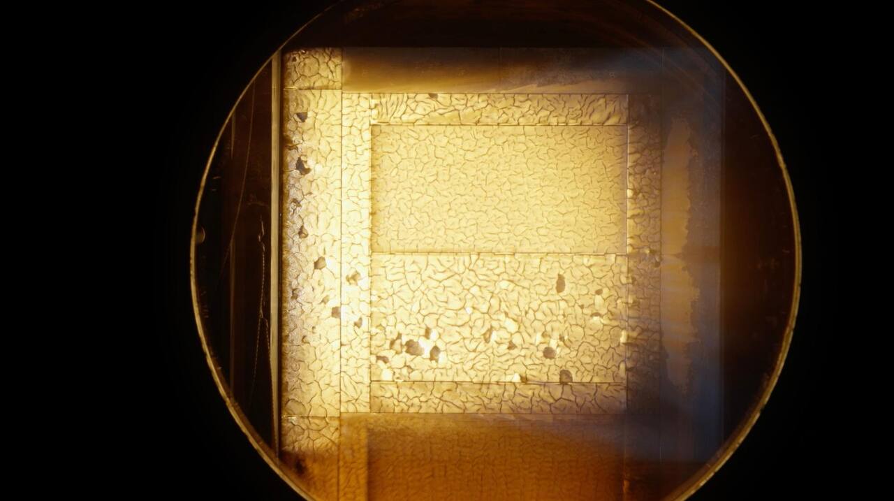
The Arc Jet Complex at NASA ARC is the agency’s principal thermal protection system test installation: four named arc jet facilities across seven test bays in two laboratory buildings, drawing on shared direct current power supplies, a steam ejector vacuum system, deionized cooling water, high pressure gas and common controls, and used to simulate the heating rates of Earth or planetary hypersonic entry so that thermal protection systems and materials can be selected, validated and qualified [1][2].
Laboratory data
Section titled “Laboratory data”| Parameter | Value |
|---|---|
| Operator | NASA ARC, Thermophysics Facilities Branch [1][4][6] |
| Location | Moffett Field, California, United States [1] |
| Commissioned | In thermal protection service since the 1960s; modernization study 2022 [1][2] |
| Type | Arc-heated hypersonic entry simulation for thermal protection systems [1] |
| Floor area | Not published; seven test bays in buildings N-234 and N-238 |
| Capabilities | IHF, AHF, PTF, TFD, LEAF, mARC II [1][2][6] |
| Simulant or terrain | Not applicable; the working fluid is an arc-heated gas stream |
| Instrumentation | Water-cooled copper calibration plates with Gardon gauges [5] |
| Ground truth | Calibration plate run of the test article geometry ahead of the material sample |
| Fidelity limits | Monochromatic radiant source; no single leg spans the envelope [1][5] |
| Access | Not published as a schedule; modeled mean throughput 483 runs per year |
| Cited by | Not applicable |
The scale of the supporting plant is the reason the complex exists as one installation rather than four. The facilities share two direct current power supplies, a steam ejector vacuum system, a deionized water cooling system, high pressure gas systems and controls, and the magnitude and capacity of that common equipment is the stated reason the complex is unique in aerospace testing. The steam vacuum system is a five-stage steam ejector pumping network about 300 ft long and 100 ft across at its widest, and it is what allows high-altitude flight conditions to be matched with test articles of relatively large size [2]. Cooling water is deionized because the arc heaters require coolant of very low electrical conductivity [2]. Building N-234 holds the Aerodynamic Heating Facility, on a 20 MW power supply and comprising three heaters, AHF Constricted, AHF Huels and TP3, and the Turbulent Flow Duct, also on a 20 MW supply. Building N-238 holds the Interaction Heating Facility on a 60 MW supply, which carries the highest traffic because of the flow rates and enthalpy it provides, and the Panel Test Facility on a 20 MW supply [2]. The Thermophysics Facilities Branch’s own test planning guide states the bookable envelope across the arc jet streams as input power 10 to 60 MW, bulk enthalpy 1,500 to 12,000 Btu/lbm and surface pressure 0.01 to 75 kPa, and fixes the customer-facing process of model size limits, instrumentation channel counts and scheduling that a campaign has to clear before a run [6]. Two heater families are run across the complex: a segmented, constricted heater reaching 28 MJ/kg bulk enthalpy at pressures to 1 MPa with electrode-material contamination below 10 ppm, and a Huels, vortex-stabilized heater reaching 1.7 MPa stagnation pressure but limited to about 9 MJ/kg and a higher contamination level [6].
Capabilities
Section titled “Capabilities”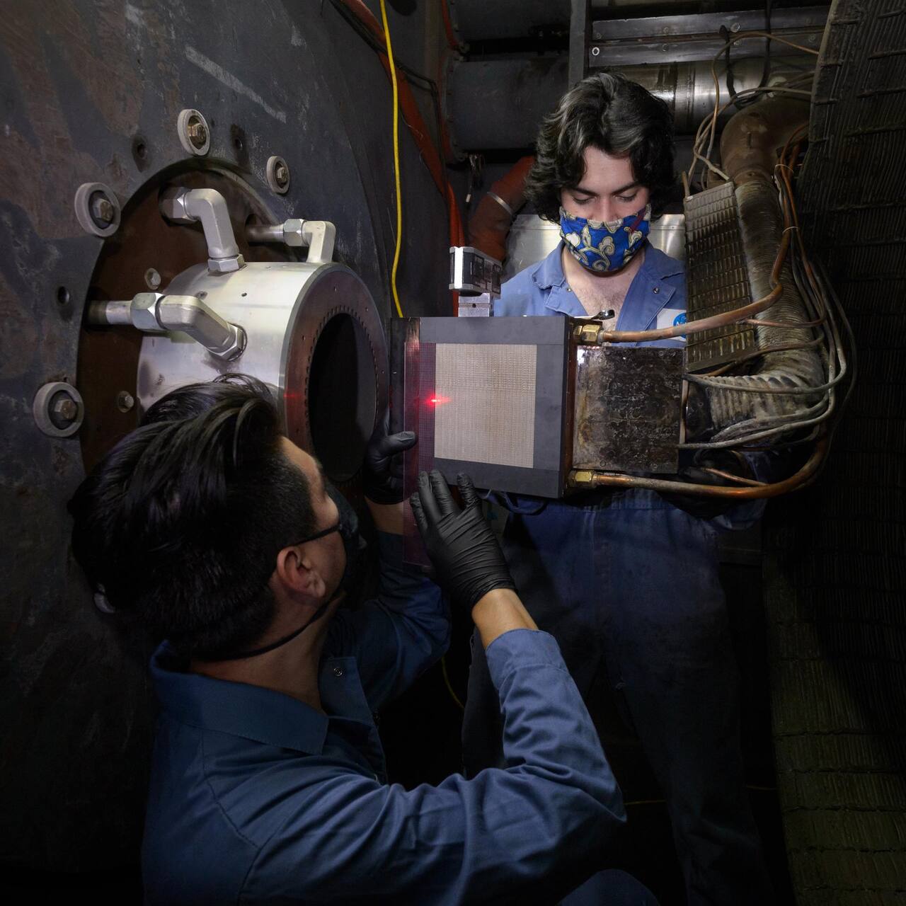
Dominic Hart. Public domain (NASA / US government work).
| Parameter | Value |
|---|---|
| Working volume | Conical nozzles 152 mm to over 1 m exit diameter [1] |
| Test article limits | Flat panels to 610 x 610 mm on the semi-elliptical nozzle |
| Vacuum | Stagnation pressures 0.01 to over 1 atm, on the steam ejector system [1][2] |
| Temperature | 7 to 47 MJ/kg bulk enthalpy; heat flux 5 to over 6000 kW/m2 [1] |
| Illumination | Radiant heating only in combination with LEAF [5] |
| Slope | Not applicable; article inclination set by the sting or panel holder |
| Gravity offload | Not applicable |
| Instrumentation | Gardon gauge calibration plate of matching geometry |
The Interaction Heating Facility runs a 60 MW Ames-designed constrictor arc heater at 1 to 9 atm arc pressure, and it is the highest-traffic leg of the complex because of the combination of flow rate and enthalpy it delivers [1][2]. Its power supply can deliver 75 MW for 30 minutes or 150 MW for 15 seconds. Interchangeable conical nozzles set the stream size, and a semi-elliptical nozzle converts it into a panel facility.
| Parameter | Value |
|---|---|
| Working volume | Conical nozzles 76 to 914 mm exit diameter |
| Test article limits | Samples to 203 mm diameter, or a 660 x 660 mm wedge |
| Vacuum | Chamber pressures 0.005 to 0.125 atm |
| Temperature | 11 to 33 MJ/kg constricted; 3.5 to 9.5 MJ/kg on the Huels heater |
| Instrumentation | Five-arm fully programmable insertion system, up to five samples per run |
Source: [1].
The Aerodynamic Heating Facility can run either a 20 MW constricted heater at 1 to 9 atm or a Hüls heater at 1 to 40 atm, which is the highest arc pressure in the complex and the reason the leg exists alongside IHF [1]. The five-arm insertion system is what makes it the throughput facility for materials screening: five articles can be exposed in a single run rather than one.
| Parameter | Value |
|---|---|
| Working volume | Semi-elliptical nozzle on a 20 MW constricted heater at 1 to 9 atm [1] |
| Test article limits | Panels of about 355 x 355 mm, surface inclination -4 to +8 degrees |
| Vacuum | Surface pressures 66 to 4700 Pa |
| Temperature | 7 to 35 MJ/kg; cold wall heat flux 6 to 340 kW/m2 |
| Instrumentation | Runs of up to 30 minutes; Gardon gauge calibration plate [1][5] |
The Panel Test Facility produces a flat-panel environment rather than a stagnation-point one. The same panel environment can be recreated in AHF or IHF with a semi-elliptical nozzle of the same family, so PTF is a routing choice rather than a unique capability, and its long run duration is what distinguishes it in practice [1][2].
| Parameter | Value |
|---|---|
| Working volume | Supersonic rectangular duct, 2 by 9 in nozzle, on a 12 MW Huels heater [1][2] |
| Test article limits | Models 203 mm high by up to 508 mm long [1] |
| Vacuum | Surface pressures 0.02 to 0.15 atm |
| Temperature | 3 to 9 MJ/kg; cold wall heat flux 20 to 700 kW/m2 |
| Instrumentation | Shear stress 5 to 70 kg/m2 across the model surface |
The Turbulent Flow Duct is the shear facility: instead of a free jet onto a stagnation point, it drives turbulent flow along a flat surface, which is the loading that erodes tile gaps, seams and coatings. It is the only leg for which surface shear stress is a published test parameter [1].
| Parameter | Value |
|---|---|
| Working volume | Four beams routed into the IHF test box |
| Test article limits | 152 x 152 mm wedge, or 432 x 432 mm panel in the spread configuration |
| Illumination | Four 50 kW continuous-wave ytterbium fiber lasers, 1070 +/- 4 nm |
| Temperature | Radiative flux to 375 W/cm2 on a wedge; 551 W/cm2 combined with IHF |
| Instrumentation | Six Gardon gauges each on radiative and convective calibration plates |
Source: [5].
The Laser Enhanced Arc jet Facility adds what an arc jet cannot produce. Uniform radiative flux is delivered to within plus or minus 6 percent across the article [5]. In the wedge configuration the system has provided up to 375 W/cm2 on a 152 by 152 mm article, and combining that with the 160 W/cm2 of convective heating IHF produces on a wedge behind a 9 in nozzle gives a combined 551 W/cm2; the panel configuration spreads the same four beams over a 432 by 432 mm square and is designed for 100 W/cm2 [5]. That separates radiative from convective heating in a way the plasma stream alone does not, and it is a requirement for EM-2 certification of the Orion thermal protection system.
mARC II
Section titled “mARC II”| Parameter | Value |
|---|---|
| Working volume | 30 kW segmented constricted heater on a Hypertherm MAX200 torch cathode [3][9] |
| Test article limits | Small material and instrument samples; scale not published |
| Vacuum | Base pressure 4 Pa after the vacuum system upgrade, versus 53 Pa before it [7] |
| Temperature | Bulk enthalpy 4 to 14 MJ/kg by energy balance or sonic-flow correlation [3][7][9] |
| Simulant or terrain | Working gas air, nitrogen or carbon dioxide |
| Instrumentation | Water-cooled Gardon gauge on a sweep arm; optical emission spectroscopy of the freestream [3][8] |
mARC II is the small-scale counterpart, built because operational complexity accompanies the high-power facilities and some programs are better suited to a smaller scale, whether for budget reasons or to test many materials or instruments quickly. Strongback, constrictor disks, anode and nozzle are oxygen-free high conductivity copper [3]. The primary distilled water loop cools both arc heater and chamber walls at about 150 L/min, and a dedicated 45 L high-pressure loop cools sensors at up to 5.7 L/min during insertion into the jet; gas supply runs through Sage Prime SIP-030-DC24 thermal mass flowmeters.
The facility’s measured envelope has moved in both directions since the initial characterization. Moving the Gardon gauge downstream to 52 and 68 mm from the nozzle exit extended the cold-wall heat flux floor down to 200 W/cm2, below the 800 to 1900 W/cm2 range of the first-generation mARC, at the cost of a systematic instrumentation defect in which measured arc current reads 0.923 times the set current [9]. A later vacuum system upgrade, a booster pump, water-cooled diffuser and heat exchanger, cut base pressure roughly 13-fold and let the nozzle run underexpanded rather than back-pressure-limited, which lowered the achievable stagnation heat flux by about a factor of four at the same current and flow settings and produced the lowest fluxes measured in the facility to date, 26 to 81 W/cm2 [7]. That result reframes the earlier 200 W/cm2 floor as an artifact of chamber back pressure rather than a limit of the heater. A laminar Navier-Stokes simulation of the same runs matched measured heat flux to within 3 to 15 percent at low arc current but diverged to 49 percent at the highest current tested, for reasons the authors could not isolate [7].
Optical emission spectroscopy of the freestream, 25 mm downstream of the nozzle exit, finds copper and silver electrode-erosion products and sodium, lithium and potassium impurities in every run tested, the sodium traced to a sodium nitrite additive in the electrode grease rather than to any test sample, which establishes the impurity as facility-inherent [8]. Anode erosion peaks during the unstable-current arc startup transient, so ramping the mass flow up slowly rather than opening the gas valve at once measurably cut startup copper emission [8]. Run duration at the facility is set by the model support hardware rather than the heater: an uncooled sweep-arm feedthrough capped runs at about 450 s, and only at minimum arc power and maximum standoff from the nozzle, until a water-cooled aluminum sleeve over the feedthrough let customer testing, including SpaceX and Blue Origin articles, run to 750 s at higher power and closer to the nozzle [10].
Instrumentation
Section titled “Instrumentation”Heat flux in a panel or wedge test is calibrated by running a water-cooled copper calibration plate of the same geometry as the test article, instrumented with Gardon gauges at fixed locations, ahead of the material samples; in LEAF the radiative and convective calibration plates carry six Gardon gauges each at matching positions, and the convective plate also takes surface pressure [5]. The complex publishes a measurements handbook as controlled branch-level documentation [4].
mARC II is instrumented for enthalpy as well as heat flux. A differential temperature sensor and flowmeter on the primary 750 L distilled water loop provides an estimate of the bulk enthalpy delivered to the plasma by energy balance, which is a facility-level measurement the larger legs obtain differently [3]. That energy-balance estimate generally reads lower than the sonic-flow correlation used for the larger arc heaters, reported for mARC II for the first time alongside the low-flux vacuum upgrade campaign [7]. Erosion and contamination are read from line-of-sight optical emission spectroscopy rather than from electrode mass loss, which biases the derived plasma temperature toward the hot jet centerline [8].
What it does not reproduce
Section titled “What it does not reproduce”Coverage in one place. No single leg spans the envelope. The four facilities differ in heater, pressure range and enthalpy range, and a panel environment that PTF produces with a semi-elliptical nozzle can also be recreated in AHF or IHF with the same nozzle family, so a campaign is routed to whichever bay reaches its conditions rather than to one large facility [1][2].
The radiation spectrum, in the laser facilities. Shock-layer radiation during entry spans the ultraviolet into the infrared, and there is no light source that can illuminate a wedge or panel at high heat flux across that range. LEAF’s fiber lasers are monochromatic at 1070 nm, which was accepted as the price of reaching the power levels required; a broader-spectrum ground facility awaits practical multi-kilowatt visible and ultraviolet lasers [5].
Chamber pressure at the small scale. mARC II’s as-built vacuum configuration holds the chamber below approximately 3 kPa through a test, which the operators note is higher than optimal, producing a slightly over-expanded jet; modifications to increase system conductance were under consideration [3].
Run duration and throughput. A PTF run can last up to 30 minutes, and exposures across the complex have run from a few minutes to over an hour [1]. Throughput is the binding constraint at the complex level: a Monte Carlo model of the legacy complex, on notional inputs of 250 working days, three test runs per day for complex testing or five for simple, and per-facility availability of 20 to 40 percent, put the mean at 483 test runs a year [2]. At mARC II, run duration is limited by the model support hardware rather than by heater power or flow, and was extended from about 450 s to 750 s by cooling the sweep-arm feedthrough rather than by any change to the arc itself, which is a caution against reading a legacy duration figure as a heater limit anywhere in the complex [10].
Instrumentation artifacts at the small scale. mARC II’s arc current measurement reads a consistent 0.923 of the set current across every condition run, for a cause the operators have not isolated, and its vacuum system state changes the achievable heat flux at a fixed arc setting by a factor of four, so a flux number from this facility is not comparable across campaigns without knowing which vacuum configuration and which current calibration produced it [7][9].
Campaigns run there
Section titled “Campaigns run there”Thermal protection system development, 1960s to present. The complex has supported Apollo, Space Shuttle, Viking, Pioneer-Venus, Galileo, Mars Pathfinder, Stardust, X-33, X-34, SHARP-B1 and B2, X-37 and the two Mars Exploration Rovers, in the roles of material selection, validation and qualification [1].
Orion thermal protection, LEAF, 2018 onward. LEAF testing of Orion thermal protection, including the tiled Avcoat heatshield and its compression pads, is a requirement for EM-2 certification of flight readiness, and it is run as a combined radiant and convective exposure in the IHF test box rather than in either mode alone [5].
mARC II characterization, 2020 to 2024. Initial characterization of the upgraded second-generation miniature arc jet reported measured arc current and voltage, column and chamber pressures, mass flow rates and initial column diagnostics, at settings including 40 A and 100 A at 0.25 g/s of air, with the facility undergoing integrated systems testing at the time [3]. Later campaigns pushed the envelope down to 200 W/cm2 by relocating the heat flux gauge [9], then down again to 26 to 81 W/cm2 after a vacuum system upgrade removed a back-pressure limit that the earlier campaigns had mistaken for a heater floor [7]. Optical emission spectroscopy of the freestream, run separately, established that electrode erosion and grease-borne sodium contaminate the flow independent of any test article [8].
Customer testing with an extended run-duration envelope, mARC II. After a water-cooled sleeve was fitted over the model support’s vacuum feedthrough, customer runs for SpaceX and Blue Origin articles reached 750 s at higher power and closer standoff than the uncooled 450 s limit allowed, validated by a support thermocouple that read 160 C against an 87 K more conservative thermal-model prediction [10].
Ground tests against flight
Section titled “Ground tests against flight”Ground arc jets are one of several ways to test an entry heat shield, and none of them reproduces flight entry as a whole. The families are: arc-heated free jets and panel streams at Ames, which supply convective heating at controlled enthalpy and pressure on articles up to panel scale; laser-augmented arc jets, which add a radiative component for the Orion class of heat shield (LEAF, demonstrated in the IHF test box) [5]; small-scale arc jets such as mARC II, which trade envelope for turnaround [3]; shock tubes and ballistic ranges in the same branch, which cover radiating shock layers and free-flight aerodynamics rather than material response [6]; and computational prediction, which the arc jet data anchor [7]. Only the first three expose material to a flowing plasma.
Flight data show how far prediction anchored on ground tests can be from the outcome. The Galileo probe carried ten ablation detectors in its carbon phenolic forebody through a Jovian entry, and the measured recession was far below prediction at the stagnation point and above it on the frustum, so the thinnest remaining shield sat at the most critical location [11]. The Mars 2020 as-flown reconstruction compares reconstructed convective heating with fully catalytic and supercatalytic computational cases, the same catalysis assumption that arc jet cold-wall heat flux values carry [12][1]. The Ames complex is cited as heritage for Galileo, Stardust, the Mars Exploration Rovers and Mars Science Laboratory, which is a list of programs, not a record of test-to-flight agreement [1].
Combined heating and the TPS programs it serves
Section titled “Combined heating and the TPS programs it serves”LEAF’s delivered capability has been characterized in three conference decks. Integrated system verification covered nearly 40 runs on burn plates, Gardon gauge calibration plates, coated non-ablative tiles and Avcoat, with beam uniformity within 6 percent of average irradiance and run-to-run variability under 11 percent [15]. Avcoat was run at 160 W/cm2 convective only, 168 W/cm2 radiative only and 88 plus 83 W/cm2 combined, and the three exposures produced visibly different material response, which is the argument for the combined mode [15]. The combined envelope measured with a water-cooled calibration plate is 160 W/cm2 convective plus 392 W/cm2 radiative on a 15.2 cm square wedge, and 70 plus 91 W/cm2 on a 43.2 cm square panel, with the panel readings marked provisional [14]. The 2025 capability summary gives the two flat-top beam sizes and a super-Gaussian configuration, and reports that peak irradiance rises linearly with laser power; multi-beam irradiance is inferred from that linearity rather than measured [13]. None of the three reports an uncertainty budget.
The same Interaction Heating Facility supplied the arc jet campaign that matured HEEET, a woven dual-layer ablator, to TRL 6 by May 2019 [16], after heritage tape-wrapped carbon phenolic ceased to exist as a product. Design cases for Uranus and Neptune entry span 2498 to 9635 W/cm2 peak stagnation heat flux and 6.8 to 25 bar stagnation pressure, above the 5 to over 6000 kW/m2 heat flux range stated for IHF in [1]; the same campaign included a wedge shear test at an outside facility. The same talk states that Galileo recession data showed the entry environment had been underpredicted and the heat shield thickness barely adequate [11].
Entry system context
Section titled “Entry system context”An arc jet result is one input to an entry vehicle whose other elements are verified by simulation and flight reconstruction. Curiosity was the first guided (lifting) entry flown at Mars, and its guidance, navigation and control architecture is documented as requirements and design set points, not as measurements [19]. The post-flight comparison of Curiosity telemetry with pre-entry Monte Carlo distributions found most of the sequence within 1.5 sigma, with three anomalies: deceleration above 50 km higher than modeled, low supersonic deceleration attributed to a tail wind of about 20 m/s, and a gravity error that biased terminal descent velocity; peak heat rate and total heat load were not yet reconstructed at publication [20]. Mars 2020 entry was reconstructed from a single flight, for the attitude controller [17] and for the mode state machine [18], and neither establishes landing accuracy. An EDL systems analysis ranked seven candidate technologies for a later Mars architecture by simulation, cost bin and qualitative risk, not by test [29]. The Mars Sample Return entry concept for the sample retrieval lander and the Earth entry system is a 2021 status presentation of plans [30].
Titan entry is checked against flight in a different way. The Dragonfly team reran the Huygens descent in a six degree of freedom simulation with its own atmosphere model and matched sensed acceleration at parachute deployment to about 3 m/s2 [21]. A multi-body parachute model did not remove the attitude excursions seen in that rerun, so they are not a parachute modeling artifact, and its bridle parameters were tuned to Huygens flight data [22].
Venus conditions elsewhere
Section titled “Venus conditions elsewhere”The Ames complex does not reproduce the Venus surface, which is a sustained thermal and chemical soak rather than an entry heating pulse. The NASA Glenn Extreme Environment Rig was built because earlier Venus chambers held about 1 cubic foot and reproduced only CO2 and N2; the design paper predates commissioning and has no achieved chemistry data [23]. Tests in that rig include a 60 Earth-day exposure of a prototype alumina package gave a split verdict on a single campaign without replication [24], and a materials exposure at 92 bar and 467 C ranked metals, coatings and ceramics by weight gain per area, a metric the report’s own curation flags as confounded by density [25]. A ten chip silicon carbide electronics board failed at 107 C during heat up in the same chamber, and the stated failure mechanism does not fully fit the observation [26]. The atmosphere models behind these tests are built on Pioneer Venus and Venera data unchanged since 2005 [28]. A Compass concept study for an uncooled lander at 467 C and 9.3 MPa is a point design, and none of its numbers are measurements [27].
What is not established
Section titled “What is not established”The envelope figures in [1] and [6] are published operating ranges, not uncertainty-bounded measurements; whether a stated maximum enthalpy can be reached together with maximum pressure on the largest article is not stated. The measurements handbook gives the reduction formulas but no uncertainty budget for an Ames heat flux, and its calibration references predate current hardware [4]. The Developmental Arc Jet figures (40 to 100 MJ/kg, planetary gases) are designed uses, not demonstrated operation [1]. LEAF is monochromatic, and the mARC II flux numbers depend on vacuum configuration and an unexplained current calibration offset [5][7][9]. No held source compares Ames arc jet results with flight measurements for a specific vehicle other than through heritage lists; the Galileo and Mars 2020 flight records are cited for context, and their test-to-flight comparison is not reproduced here.
References
- Fretter, E. F. (2005). NASA Ames Arc Jets and Range, Capabilities for Planetary Entry
. International Planetary Probe Workshop, 20070014623. Source
BibTeX
@inproceedings{fretter2005nasa, title = {NASA Ames Arc Jets and Range, Capabilities for Planetary Entry}, author = {Fretter, Ernest F.}, booktitle = {International Planetary Probe Workshop}, number = {20070014623}, pages = {313--316}, publisher = {NASA Ames Research Center}, institution = {NASA}, address = {Moffett Field, California}, year = {2005}, url = {https://ntrs.nasa.gov/citations/20070014623}, abstract = {NASA is pursuing innovative technologies and concepts as part of America's Vision for Space Exploration. The rapidly emerging field of nanotechnology has led to new concepts for multipurpose shields to prevent catastrophic loss of vehicles and crew against the triple threats of aeroheating during atmospheric entry, radiation (Solar and galactic cosmic rays) and Micrometorid/Orbital Debris (MMOD) strikes. One proposed concept is the Thermal Radiation Impact Protection System (TRIPS) using carbon nanotubes, hydrogenated carbon nanotubes, and ceramic coatings as a multi-use TPS. The Thermophysics Facilities Branch of the Space Technology Division at NASA Ames Research Center provides testing services for the development and validation of the present and future concepts being developed by NASA and national and International research firms. The Branch operates two key facilities - the Range Complex and the Arc Jets. The Ranges include both the Ames Vertical Gun Range (AVGR) and the Hypervelocity Free Flight (HFF) gas guns best suited for MMOD investigations. Test coupons can be installed in the AVGR or HFF and subjected to particle impacts from glass or metal particles from micron to _ inch (6.35-mm) diameters and at velocities from 5 to 8 kilometers per second. The facility can record high-speed data on film and provide damage assessment for analysis by the Principle Investigator or Ames personnel. Damaged articles can be installed in the Arc Jet facility for further testing to quantify the effects of damage on the heat shield s performance upon entry into atmospheric environments.} } - Scheel, J. and Smart, C. (2022). Cost and Throughput Analysis for the NASA Ames Arc Jet Modernization Program
. ICEAA Professional Development and Training Workshop, 20220006062. Source
BibTeX
@inproceedings{scheel2022cost, title = {Cost and Throughput Analysis for the NASA Ames Arc Jet Modernization Program}, author = {Scheel, Jennifer and Smart, Christian}, booktitle = {ICEAA Professional Development and Training Workshop}, number = {20220006062}, institution = {NASA}, address = {Pittsburgh, Pennsylvania}, year = {2022}, url = {https://ntrs.nasa.gov/citations/20220006062}, abstract = {NASA Ames Center is currently evaluating alternatives to modernize the Arc Jet Complex, a critical part of testing for NASA’s planetary missions. NASA’s Arc Jet Complex facilities “are used to simulate the aerothermodynamic heating that a spacecraft endures throughout hypersonic atmospheric entry, and to test candidate thermal protection system (TPS) materials and systems. “Because planetary mission schedules often have tight windows due to planetary alignment constraints, a small increase in schedule could result in a two-year delay. Such a delay could increase the cost of a $1billionmissionbyhundreds of millions of dollars due to project personnel pay and clean room storage. To avoid these costs, the authors support NASA Ames in evaluating return on investment (ROI) and effectiveness of alternatives for modernizing the complex. The first input into the ROI is the deconstruction and construction cost estimates, which are developed using independent research on highly specialized subsystems, vendor quotes, and Unified Facilities Criteria (UFC), depending on the facility and work package. One of the measures of effectiveness is throughput analysis of the test bays, as a main goal of the modernization is to increase the number of possible test runs per year. This analysis is conducted via a probabilistic simulation and accounts for a variety of stochastic factors that influence the sequence of test runs, such as the facility availability; test complexity; the need to pause to assess test results; test failure; and the possibility of a system failure. The methodologies for both these analyses are discussed, along with the challenges presented due to the unique nature of the highly specialized test equipment} } - Macdonald, M. E., Haw, M. A., Philippidis, D., Schickele, D. E., Luis, D. Z. F., Hartman, J. and Mc Glaughlin, M. S. (2020). Initial Characterization of the 30 kW Miniature Arc Jet (mARC II) at NASA Ames Research Center
. AIAA AVIATION Forum, 20205001839. Source
BibTeX
@inproceedings{macdonald2020initial, title = {Initial Characterization of the 30 kW Miniature Arc Jet (mARC II) at NASA Ames Research Center}, author = {Macdonald, Megan E. and Haw, Magnus A. and Philippidis, Daniel and Schickele, Daniel E. and Luis, Diana Z. F. and Hartman, Joe and Mc Glaughlin, Mark S.}, booktitle = {AIAA AVIATION Forum}, number = {20205001839}, institution = {NASA}, year = {2020}, doi = {10.2514/6.2020-3108}, abstract = {The second-generation Miniature Arc jet Research Chamber (mARC II) at NASA Ames is undergoing integrated systems testing. Once fully operational, this facility will be added to the range of available test facilities operated by the NASA Ames Thermophysics Facilities Branch, with primary focus on applications such as new arc jet flow diagnostics and new arc column diagnostics. Initial characterization of the mARC II is reported here, specifically, measured arc current, arc voltage, column and chamber pressures, mass flow rates, and initial emission measurements carried out at a range of conditions.} } - Cheng, J. and Eddlemon, S. G. (2021). NASA Ames Arc Jet Complex Measurements Handbook
. NASA, 20210019364. Source
BibTeX
@techreport{cheng2021nasa, title = {NASA Ames Arc Jet Complex Measurements Handbook}, author = {Cheng, Jerry and Eddlemon, Scott G.}, number = {20210019364}, institution = {NASA}, year = {2021}, url = {https://ntrs.nasa.gov/citations/20210019364}, abstract = {The Arc Jet Measurement System Handbook will serve as a reference of the calculations and formulas used by the Arc Jet Complex Data Acquisition System. It is the objective that Code ASF personnel and experimenters will be able to manually reproduce data calculations performed by the Arc Jet Data Acquisition System using these formulas as a guide.} } - Cushman, G., Alunni, A., Balboni, J., Zell, P., Hartman, J. and Empey, D. M. (2018). The Laser Enhanced Arc-Jet Facility (LEAF-Lite): Simulating Convective and Radiative Heating with Arc-Jets and Multiple 50-kW CW Lasers
. Joint Thermophysics and Heat Transfer Conference. Source
BibTeX
@inproceedings{cushman2018laser, title = {The Laser Enhanced Arc-Jet Facility (LEAF-Lite): Simulating Convective and Radiative Heating with Arc-Jets and Multiple 50-kW CW Lasers}, author = {Cushman, Geoff and Alunni, Antonella and Balboni, John and Zell, Pete and Hartman, Joe and Empey, Daniel M.}, booktitle = {Joint Thermophysics and Heat Transfer Conference}, publisher = {American Institute of Aeronautics and Astronautics}, address = {Atlanta, Georgia}, year = {2018}, doi = {10.2514/6.2018-3273}, abstract = {LEAF-Lite (Laser Enhanced Arc-Jet Facility) is a radiative laser heating facility that has been added to the 60 MW Interaction Heating Facility (IHF) convective plasma arc-jet located at NASA Ames Research Center. Together, these two systems can simulate both convective and radiative heating at heat fluxes reaching 551 W/cm2 by simultaneously combining a highest measured heat flux of 160 W/cm2 convective and 391 W/cm2 radiative heating on a 152-mm x 152-mm wedge model configuration. Adding radiant heating to an existing convective facility better simulates Earth atmospheric entry from hyperbolic lunarreturn speeds. The radiative heat is provided by multiple 50-kW CW IR lasers, which is nearly uniform across the illuminated surface with a total variation less than 6%, while the convective heat is provided by a high enthalpy plasma arc-jet. In a later phase, the facility will expand to test panel test articles of 432-mm x 432-mm and provide 100 W/cm2 of radiative heating in a plasma convective flow environment. The paper describes this new combined heating capability, its current testing conditions, and the unique application of the laser system with respect to the Orion test flight lunar orbits.} } - Hui, F. C. L. and Terrazas-Salinas, I. (2025). Test Planning Guide for NASA Ames Research Center Arc Jet Complex, Ballistic Range Complex, and Electric Arc-Driven Shock-Tube Facility
. NASA Ames Research Center, Thermophysics Facilities Branch, A029-9701-XM3 Rev. K. Source
BibTeX
@techreport{hui2025test, title = {Test Planning Guide for {NASA Ames Research Center} Arc Jet Complex, Ballistic Range Complex, and Electric Arc-Driven Shock-Tube Facility}, author = {Hui, Frank C. L. and Terrazas-Salinas, Imelda}, number = {A029-9701-XM3 Rev. K}, institution = {NASA Ames Research Center, Thermophysics Facilities Branch}, year = {2025}, url = {https://www.nasa.gov/thermophysics-facilities-test-planning-information/} } - Rodrigues, J., MacDonald, M. E., Haw, M. A., Martinez, R., Philippidis, D. and Colom, S. (2024). Defining the Operational Envelope for Air Flows in the Miniature Arc-Jet Research Chamber (mARC II)
. AIAA AVIATION Forum and ASCEND. Source
BibTeX
@inproceedings{rodrigues2024defining, title = {Defining the Operational Envelope for Air Flows in the Miniature Arc-Jet Research Chamber ({mARC II})}, author = {Rodrigues, Jocelino and MacDonald, Megan E. and Haw, Magnus A. and Martinez, Ramon and Philippidis, Daniel and Colom, Sebastian}, booktitle = {AIAA AVIATION Forum and ASCEND}, year = {2024}, doi = {10.2514/6.2024-3553}, abstract = {The second-generation 30 kW miniature Arc-jet Research Chamber (mARC II) at NASA Ames Research Center produces high enthalpy flows relevant for entry systems ground testing. The mARC II facility has recently undergone upgrades, including the installation of a new vacuum system to address the issues preventing it from maintaining underexpanded flow under test conditions. In this work, we present data obtained from an Integrated Systems Testing campaign and provide an initial assessment of arc-jet performance following the upgrades. Air is used as the working gas for the standard mARC II arc-heater configuration with two constrictor disks. Seven runs were investigated for five test conditions to assess the lowest achievable stagnation point heat fluxes for air flow rates of 0.15 or 0.25 g/s. The heat flux was measured using a water-cooled Gardon gauge (⌀4.76 mm, 3/16" hemispherical) at 70 mm from the nozzle exit plane. The new vacuum system produced test box pressures in the medium (fine) vacuum range (∼0.03 torr, 4 Pa) prior to gas addition and successfully maintained underexpanded flow after gas addition. The upgrade yielded a ∼4X reduction in heat flux relative to the previous system for the same set test conditions. We report the lowest heat fluxes measured in mARC II to date, ranging from 26 to 81 W/cm², for sonic flow enthalpies of 4–14 MJ/kg. Bulk enthalpies estimated using an energy balance method (EB²) are reported for the first time using mARC II. Initial data suggests EB² generally estimates lower enthalpies than sonic flow methods for mARC II. Lastly, laminar axisymmetric Navier–Stokes simulations were performed using the NASA DPLR code. Numerical heat flux results show good agreement with experiments at low arc powers (3–15% difference at the minimum set arc current), but discrepancy increases with arc power (49% difference at the maximum set arc current).} } - Luís, D. and MacDonald, M. E. (2021). Emission Spectroscopy Characterization of Electrode Species in the Freestream Flow at the NASA Ames Miniature Arc Jet II Facility
. Journal of Quantitative Spectroscopy and Radiative Transfer. Source
BibTeX
@article{luis2021emission, title = {Emission Spectroscopy Characterization of Electrode Species in the Freestream Flow at the {NASA Ames} Miniature Arc Jet {II} Facility}, author = {Luís, Diana and MacDonald, Megan E.}, journal = {Journal of Quantitative Spectroscopy and Radiative Transfer}, volume = {272}, pages = {107752}, year = {2021}, doi = {10.1016/j.jqsrt.2021.107752} } - MacDonald, M. E., Haw, M. A., Martinez, R. and Colom, S. (2023). Characterizing Heat Flux in the Miniature Arc Jet Research Chamber (mARC II)
. NASA Ames Research Center, 20230006452. Source
BibTeX
@techreport{macdonald2023characterizing, title = {Characterizing Heat Flux in the Miniature Arc Jet Research Chamber ({mARC II})}, author = {MacDonald, Megan E. and Haw, Magnus A. and Martinez, Ramon and Colom, Sebastian}, number = {20230006452}, institution = {NASA Ames Research Center}, year = {2023}, doi = {10.2514/6.2023-3298}, abstract = {View Video Presentation: https://doi.org/10.2514/6.2023-3298.vid The second-generation miniature Arc jet Research Chamber (mARC II) at NASA Ames Research Center produces small-scale high enthalpy flows relevant for entry systems ground testing. This facility is aimed at applications such as new arc jet flow diagnostics and new arc column diagnostics. The mARC system has previously been shown capable of delivering heat fluxes between 800 and 1900 W/cm2. New work shows that the facility is also capable of delivering heat fluxes as low as 200 W/cm2.} } - Edwards, T., Rodrigues, J. and Philippidis, D. (2026). Extending mARC II Arc-Jet Test Duration via Design and Implementation of a Model System Cooling Solution
. AIAA AVIATION Forum. Source
BibTeX
@inproceedings{edwards2026extending, title = {Extending {mARC II} Arc-Jet Test Duration via Design and Implementation of a Model System Cooling Solution}, author = {Edwards, Thomas and Rodrigues, Jocelino and Philippidis, Daniel}, booktitle = {AIAA AVIATION Forum}, address = {San Diego, California}, year = {2026}, doi = {10.2514/6.2026-4311}, abstract = {The mARC II is a 30 kW arc-jet facility at NASA Ames Research Center used to generate high-enthalpy flows for low-cost thermal protection system (TPS) technology development. Sustained operation of downstream instrumentation and material samples is constrained by thermal loading transmitted through the arc-jet test environment, limiting achievable run times and experimental throughput. This work presents the design, integration, and validation of a cooling sleeve implemented on the sweep arm drive motor feedthrough to mitigate thermal accumulation during testing. The addition of the cooling sleeve is a simple, robust upgrade that translates directly into enhanced facility capability by supporting longer run durations, reduced turnaround time, and higher throughput.} } - Milos, F. S. (1997). Galileo Probe Heat Shield Ablation Experiment
. Journal of Spacecraft and Rockets, 6. Source
BibTeX
@article{milos1997galileo, title = {Galileo Probe Heat Shield Ablation Experiment}, author = {Milos, Frank S.}, journal = {Journal of Spacecraft and Rockets}, volume = {34}, number = {6}, pages = {705--713}, year = {1997}, doi = {10.2514/2.3293}, abstract = {Covers advancements in spacecraft and tactical and strategic missile systems, including subsystem design and application, mission design and analysis, materials and structures, developments in space sciences, space processing and manufacturing, space operations, and applications of space technologies to other fields.} } - Mars 2020 Entry, D. and Landing Team. (2023). Mars 2020 Entry, Descent & Landing As-Flown Reconstruction Report
. Jet Propulsion Laboratory, California Institute of Technology, JPL Publication 22-1. Source
BibTeX
@techreport{mars2023mars, title = {Mars 2020 Entry, Descent & Landing As-Flown Reconstruction Report}, author = {{Mars 2020 Entry, Descent} and {Landing Team}}, number = {JPL Publication 22-1}, institution = {Jet Propulsion Laboratory, California Institute of Technology}, year = {2023}, doi = {10.48577/jpl.16mnyf}, abstract = {On February 18, 2021, amidst a global pandemic sweeping the nation and the world, the Perseverance rover safely completed its autonomous landing in Jezero Crater. The largest, heaviest, and most complex planetary rover ever built depended on its seven-minute entry, descent, and landing (EDL) sequence to touch down safely at the most dangerous landing site ever attempted on Mars. Building upon the success of the Mars Science Laboratory (MSL) mission, the Mars 2020 EDL system preserved as much of the MSL EDL architecture as possible while simultaneously fixing issues identified both pre- and post-MSL’s landing, adding mission enabling new EDL capabilities, and accommodating new mission-enhancing payloads. Reconstruction results to date have shown that the Mars 2020 EDL system performed largely as expected. Issues identified with MSL’s landing were successfully addressed during the Mars 2020 landing. The mission’s two new landing capabilities, range trigger and terrain relative navigation, proved critical in identifying and reaching a safe landing target within the hazardous Jezero Crater landing site, a site deemed too hazardous for previous landing systems. Finally, new EDL instrumentation and a new EDL camera suite gave the team greater insight into the landing performance and brought the world along for the ride. This As-Flown Reconstruction Report details the design, development challenges, pre-flight expectations, and flight performance of almost all aspects of the Mars 2020 EDL system. While this report captures the best understanding of the system as of the time of publication, no one knows better than this team that additional time and scrutiny will yield further insights; the team’s scrutiny of the MSL EDL system throughout the development of Mars 2020 led to several fixes and improvements to the EDL design. As a result, this report is a snapshot in time of the team’s best understanding of the performance of the system; expect that understanding to grow and evolve with future efforts. The Mars 2020 EDL team faced numerous challenges, some expected, some not, over the project’s lifecycle. Their engineering prowess, creativity, dedication, and can-do attitude allowed the tight-knit team to face each of these challenges and overcome them. This report documents their story. With Mars 2020’s successful landing, the edge of the Mars landing envelope has been pushed out once again, enabling the first controlled aircraft flights on another planet by the Ingenuity helicopter, the search for evidence of past life by the Perseverance rover, and the beginning of the long-envision Mars sample return campaign.} } - MacDonald, M. E., Cushman, G. A., Martinez, K. D. and Alunni, A. I. (2025). Capability Summary for the 200-kW Laser Enhanced Arc Jet Facility (LEAF), 20250005521. ntrs.nasa.gov/citations/20250005521
BibTeX
@misc{macdonald2025capability, title = {Capability Summary for the 200-{kW} Laser Enhanced Arc Jet Facility ({LEAF})}, author = {MacDonald, Megan E. and Cushman, Geoffrey A. and Martinez, Kyle D. and Alunni, Antonella I.}, howpublished = {Presentation at the NASA Ames Research Center, Entry Systems and Technology Division}, number = {20250005521}, year = {2025}, url = {https://ntrs.nasa.gov/citations/20250005521}, abstract = {The 200-kW Laser Enhanced Arc Jet Facility (LEAF) at the Interaction Heating Facility (IHF) arc jet at NASA Ames Research Center has enabled simultaneous radiative and convective heating of material samples at high heat flux levels. During LEAF operation, IHF can convectively heat material samples with heat fluxes up to 0.16 kW/cm<sup>2</sup> using the conical 22.86-cm nozzle or up to 0.085 kW/cm<sup>2</sup> using the semi-elliptic nozzle. The LEAF radiant heating capability consists of four 50-kW 1070-nm lasers, and each laser can be configured independently to a variety of beam shapes. In flat-top square configuration, irradiance levels of up to 0.1 kW/cm<sup>2</sup> total have been demonstrated over a 43.2 x 43.2 cm area, and irradiance levels up to 0.4 kW/cm<sup>2</sup> total have been demonstrated over a 15.2 x 15.2 cm area. In super-Gaussian configuration, LEAF can deliver a peak irradiance of up to 45 kW/cm<sup>2</sup> total for a 1/e2 radius of 1.5 cm or up to 12 kW/cm<sup>2</sup> total at a 1/e2 radius of 3 cm. Beam sizes between these two are also available. Recently expanded capabilities include the simultaneous operation of all four lasers in super-Gaussian configuration. This presentation includes measured irradiance values for flat-top square beam and super-Gaussian beam data taken over the lifetime of the LEAF system. The presentation also covers the two methods used for irradiance calibration: the lower irradiance water-cooled calibration plate with embedded Gardon gauges, and the higher irradiance optical beam profiling calibration with an infrared camera. Comparison between the two methods in the overlapping region gives confidence in both methods.} } - MacDonald, M. E., Cushman, G. A., Martinez, R. and Alunni, A. I. (2023). Simultaneous Convective and Radiative Heating of Materials with the 200 kW Laser Enhanced Arc Jet Facility (LEAF), 20230008351. ntrs.nasa.gov/citations/20230008351
BibTeX
@misc{macdonald2023simultaneous, title = {Simultaneous Convective and Radiative Heating of Materials with the 200 {kW} Laser Enhanced Arc Jet Facility ({LEAF})}, author = {MacDonald, Megan E. and Cushman, Geoffrey A. and Martinez, Ramon and Alunni, Antonella I.}, howpublished = {Presentation at the NASA Ames Research Center, Entry Systems and Technology Division}, number = {20230008351}, year = {2023}, url = {https://ntrs.nasa.gov/citations/20230008351}, abstract = {Recent installation of the 200-kW Laser Enhanced Arc Jet Facility (LEAF) at the Interaction Heating Facility (IHF) arc jet at NASA Ames Research Center has enabled combined heating of material samples. The LEAF system is permanently located adjacent to IHF. During LEAF operation, IHF can convectively heat material samples with heat fluxes up to 0.16 kW/cm<sup>2</sup> using the 22.86-cm nozzle or up to 0.07 kW/cm<sup>2</sup> using the truncated semi-elliptic nozzle. LEAF can deliver radiant heating with various profiles and sizes to a material sample. In flat-top square configuration, irradiance levels of nearly 0.1 kW/cm<sup>2</sup> have been demonstrated over a 43.2 x 43.2 cm area, and irradiance levels up to 0.39 kW/cm<sup>2</sup> have been demonstrated over a 15.2 x 15.2 cm area. LEAF can also be configured to deliver a super-Gaussian profile over a variety of beam diameters (1.8 to 5.6 cm). This configuration has been demonstrated up to peak irradiance levels of 25.7 kW/cm<sup>2</sup> per laser at the smallest, 1.8 cm, diameter setting. The LEAF system is composed of four 50-kW lasers, so it can also be configured to simultaneously deliver two different beam shapes (e.g., one square beam and one super-Gaussian beam).} } - Venkatapathy, E. (2018). Testing with the Laser-Enhanced Arc Jet Facility (LEAF) at NASA Ames Research Center, 20180006634. ntrs.nasa.gov/citations/20180006634
BibTeX
@misc{venkatapathy2018testing, title = {Testing with the Laser-Enhanced Arc Jet Facility ({LEAF}) at {NASA Ames Research Center}}, author = {Venkatapathy, Ethiraj}, howpublished = {Presentation at the NASA Ames Research Center, Entry Systems and Technology Division}, number = {20180006634}, year = {2018}, url = {https://ntrs.nasa.gov/citations/20180006634}, abstract = {NASA's new Laser-Enhanced Arcjet Facility (LEAF) employs 200 kilowatts of continuous-wave fiber lasers, combined with a 60-megawatt arc plasma jet, to simulate the combined radiative and convective heating is now operational and Orion heat-shield material is undergoing testing. This upgrade to the existing Interaction Heating Facility (IHF) involves the addition of high-power fiber lasers that project 1070nm radiative energy into the existing vacuum chamber. The optically expanded laser beam enters a side window of the test chamber to form either a uniform 150 x 150 mm or a 425 x 425 mm square spot on a wedge-shaped model holder. Combined heating levels of up to 180 W/cm2 convective with either 300 W/cm2 or 100 W/cm2 are achievable. This allows the arc jet and lasers to simulate dynamic entry-heating profiles encountered during entry by the Orion crew capsule for the lunar return conditions. New computational investigations are underway to explore testing with the objective of defining ablative material failure limit. Typical arc-jet testing is performed with test article that are stagnation or wedge geometries. The existing convective heating test facility combined with test article design limits how high a combined shear, heat-flux and pressure conditions can be achieved. With the addition of laser power of 200 kW, much higher combined conditions of high heat-flux, pressure and shear is achievable on a wedge or a swept-cylinder article. Such testing possibilities will allow us to progressively increase the combined conditions and explore when an ablative TPS material may fail. The presentation provides an overview of the LEAF and present results from the on-going Orion Testing.} } - Venkatapathy, E., Ellerby, D., Gage, P., Prabhu, D. and Wercinski, P. (2019). Challenges and Opportunities For Ensuring Entry System Technology Readiness For Ice Giants Probe Missions. ntrs.nasa.gov/citations/20190027647
BibTeX
@misc{venkatapathy2019challenges, title = {Challenges and Opportunities For Ensuring Entry System Technology Readiness For Ice Giants Probe Missions}, author = {Venkatapathy, Ethiraj and Ellerby, Don and Gage, Peter and Prabhu, Dinesh and Wercinski, Paul}, howpublished = {Presentation at the Ice Giant Systems Workshop}, year = {2019}, url = {https://ntrs.nasa.gov/citations/20190027647}, abstract = {The Ice Giants represent a distinct class of planets within our solar system, and appear to be similar to most exoplanets that have been detected thus far. Exploring Ice Giants in our Solar System would allow us to better understand their formation and evolution processes, and thus help establish scientific links to exoplanets. In situ exploration using probes similar to Galileo, along with an orbiter or a relay spacecraft, will require entry followed by deployment of the descent probe containing science instruments into Uranus or Neptune atmosphere. The challenge is not in the deployment of the probe, but in the atmospheric entry prior to deployment. The entry system has to have a capable, robust and efficient ablative thermal protection system (TPS) designed to protect the descent probe from the thermal and mechanical entry loads. Although entries into Ice Giants may not be as demanding as the Galileo entry at Jupiter, the entry environments will be more severe than environments for Mars, Sample Return missions, and Venus, and will therefore require robust TPS. While Galileo Probe’s success, nearly 25 years ago, should give us confidence, the recession data from the Galileo entry informs us that the entry environment was under predicted and the design thickness was barely adequate. The lesson learned from Galileo probe for future Ice Giant missions will require us to be cautious and demand a more robust design. The TPS technology used on Galileo entry system no longer exists due to atrophy of manufacturing processes. Instead of attempting to revive Galileo-legacy TPS technology, NASA invested in a new and innovative TPS called HEEET (Heat-shield for Extreme Entry Environment Technology). HEEET has been matured, and is now ready to support future missions not only to the Ice Giants but also for Venus, high-speed sample return, and Saturn probe missions. This lead talk, intended for the technology section of the workshop, will cover entry, descent, and deployment (EDD), with an emphasis on entry. A brief history of the TPS challenges for extreme entry missions will be given along with a quick overview of the concept of operations for EDD. The development and maturation of HEEET system capability will be described. Data gathered in ground-test facilities in the US will be highlighted to show that the technology is mature and ready for Ice Giant missions. All thermal protection systems carry some risk as a result of ground test limitations and Ice Giant missions present some unique challenges. These challenges are not only technical, but also due to limitations in the currently established manufacturing and integration. In addition, the concerns that arise due to potential for atrophy for future Ice Giant mission a decade or more from now will be analyzed. Plausible avenues for mitigation will be presented. There are two companion planned presentations by Dr. Prabhu and Dr. Hwang will dive deeper in the challenges and opportunities. This intended talk will set the stage for their presentations.} } - Brugarolas, P. and Way, D. W. (2021). Mars 2020 Perseverance Entry Controller Design and Flight Reconstruction
. AAS/AIAA Astrodynamics Specialist Conference, AAS 21-601. Source
BibTeX
@inproceedings{brugarolas2021entry, title = {Mars 2020 Perseverance Entry Controller Design and Flight Reconstruction}, author = {Brugarolas, Paul and Way, David W.}, booktitle = {AAS/AIAA Astrodynamics Specialist Conference}, number = {AAS 21-601}, year = {2021}, url = {https://dataverse.jpl.nasa.gov/dataset.xhtml?persistentId=hdl:2014/55195} } - Brugarolas, P. (2021). Mars 2020 Perseverance Entry Descent and Landing Guidance Navigation and Control
. AAS/AIAA Astrodynamics Specialist Conference, AAS 21-600. Source
BibTeX
@inproceedings{brugarolas2021mars, title = {Mars 2020 Perseverance Entry Descent and Landing Guidance Navigation and Control}, author = {Brugarolas, Paul}, booktitle = {AAS/AIAA Astrodynamics Specialist Conference}, number = {AAS 21-600}, year = {2021}, url = {https://dataverse.jpl.nasa.gov/dataset.xhtml?persistentId=hdl:2014/55247} } - San Martin, A. M., Lee, S. W. and Wong, E. C. (2013). The Development of the MSL Guidance, Navigation, and Control System for Entry, Descent, and Landing
. Annual AAS Guidance and Control Conference. Source
BibTeX
@inproceedings{sanmartin2013development, title = {The Development of the MSL Guidance, Navigation, and Control System for Entry, Descent, and Landing}, author = {San Martin, A. Miguel and Lee, Steven W. and Wong, Edward C.}, booktitle = {Annual AAS Guidance and Control Conference}, year = {2013}, url = {https://dataverse.jpl.nasa.gov/dataset.xhtml?persistentId=hdl:2014/44894} } - Way, D. W., Davis, J. L. and Shidner, J. D. (2013). Assessment of the Mars Science Laboratory Entry, Descent, and Landing Simulation
. AAS/AIAA Space Flight Mechanics Meeting. Source
BibTeX
@inproceedings{way2013assessment, title = {Assessment of the Mars Science Laboratory Entry, Descent, and Landing Simulation}, author = {Way, David W. and Davis, J. L. and Shidner, Jeremy D.}, booktitle = {AAS/AIAA Space Flight Mechanics Meeting}, pages = {1-16}, institution = {NASA Langley Research Center}, address = {Kauai, HI}, year = {2013}, doi = {10.1109/aero.2013.6497404}, abstract = {On August 5, 2012, the Mars Science Laboratory rover, Curiosity, successfully landed inside Gale Crater. This landing was only the seventh successful landing and fourth rover to be delivered to Mars. Weighing nearly one metric ton, Curiosity is the largest and most complex rover ever sent to investigate another planet. Safely landing such a large payload required an innovative Entry, Descent, and Landing system, which included the first guided entry at Mars, the largest supersonic parachute ever flown at Mars, and a novel and untested Sky Crane landing system. A complete, end-to-end, six degree-of-freedom, multi-body computer simulation of the Mars Science Laboratory Entry, Descent, and Landing sequence was developed at the NASA Langley Research Center. In-flight data gathered during the successful landing is compared to pre-flight statistical distributions, predicted by the simulation. These comparisons provide insight into both the accuracy of the simulation and the overall performance of the vehicle.} } - Pensado, A. R., Robb, C., Winski, R., Williams, J., Belair, M. W. and Lorenz, R. D. (2025). Assessing Huygens Probe Entry, Descent, and Landing at Titan Simulation using Dragonfly Atmosphere Model
. AIAA SCITECH Forum. Source
BibTeX
@inproceedings{pensado2025assessing, title = {Assessing Huygens Probe Entry, Descent, and Landing at Titan Simulation using Dragonfly Atmosphere Model}, author = {Pensado, Alejandro R. and Robb, Caleb and Winski, Richard and Williams, James and Belair, Michael W. and Lorenz, Ralph D.}, booktitle = {AIAA SCITECH Forum}, year = {2025}, doi = {10.2514/6.2025-2238}, abstract = {Dragonfly is a New Frontiers Program mission that will deliver a rotorcraft to Saturn’s moon, Titan. This mission follows Huygens as the previous mission that successfully landed a vehicle on Titan. A flight mechanics simulation of Dragonfly’s Entry, Descent, and Landing sequence has been developed using the Program to Optimize Simulated Trajectories II. The simulation incorporates several subsystem models, including aerodynamics, gravity, and mass properties, to fully capture the multi-body six degree of freedom dynamics. Among all the subsystem models that inform the Entry, Descent, and Landing dynamics, the atmosphere model of Titan is a critical component. The atmosphere model characterizes the density, temperature, pressure, and winds that the entry vehicle experiences during the descent. This impacts several aspects of the descent such as the peak heating, aerodynamics, parachute release conditions, the dynamics of the vehicle and parachutes, and the landing ellipse. In the course of developing Dragonfly, an updated model of the Titan atmosphere has been created corresponding to Dragonfly’s arrival in the mid-2030s, approximately one Titan year after the Huygens mission successfully landed a probe on Titan. This work leverages previous work done to investigate Huygens EDL sequence to assess the atmosphere model developed for Dragonfly. This is done by utilizing the updated Titan atmosphere model, the Dragonfly atmosphere model, within the Huygens POST2-based flight simulation with the goal of characterizing the differences between the atmospheric models and assessing how the Dragonfly atmosphere model impacts Huygens entry dynamics.} } - Robb, C., Pensado, A. R., Winski, R. G., Williams, J. W. and Manwell, M. (2026). Huygens Probe Entry, Descent, and Landing Dynamics Assessment Using a Multi-Body Parachute Model
. AIAA SCITECH Forum. Source
BibTeX
@inproceedings{robb2026huygens, title = {Huygens Probe Entry, Descent, and Landing Dynamics Assessment Using a Multi-Body Parachute Model}, author = {Robb, Caleb and Pensado, Alejandro R. and Winski, Richard G. and Williams, James W. and Manwell, Michael}, booktitle = {AIAA SCITECH Forum}, year = {2026}, doi = {10.2514/6.2026-1956}, abstract = {The Dragonfly project is a New Frontiers Program mission that is slated to launch in 2028 and deliver a rotorcraft to Titan, Saturn’s largest moon. With the launch date approaching, there is an increased focus on the validation and verification of models that are used by the trajectory simulations. One of the models that contributes the most to the uncertainty of the entry, descent, and landing simulation is the atmosphere. Since Huygens is the only mission that has collected in-situ measurements during a descent, a current plan for the validation of the atmosphere model centers around reconciling that flight data with the current atmosphere model used by the Dragonfly flight mechanics team. To complete this, a 6 degree-of-freedom, multi-body simulation has been created using the Program to Optimize Simulated Trajectories 2 (POST2), the prime simulation tool for Dragonfly Entry and Descent, to predict the dynamics of Huygens using the reconciled models. The dynamics predicted by the simulation are then compared to flight data where possible and the previous analysis that was published by the authors last year. Current results show agreement to the available flight data, with an emphasis placed on the metrics that were flagged in the last analysis. The reconciliation is set to continue as areas of concern will be reported and inspected by the model developer.} } - Kremic, T., Vento, D., Lalli, N. and Palinski, T. (2014). Extreme Environment Simulation - Current and New Capabilities to Simulate Venus and Other Planetary Bodies
. IEEE Aerospace Conference, 20140013390. Source
BibTeX
@inproceedings{kremic2014extreme, title = {Extreme Environment Simulation - Current and New Capabilities to Simulate Venus and Other Planetary Bodies}, author = {Kremic, Tibor and Vento, Dan and Lalli, Nick and Palinski, Timothy}, booktitle = {IEEE Aerospace Conference}, number = {20140013390}, pages = {1-9}, institution = {NASA}, year = {2014}, doi = {10.1109/aero.2014.6836350}, abstract = {Science, technology, and planetary mission communities have a growing interest in components and systems that are capable of working in extreme (high) temperature and pressure conditions. Terrestrial applications range from scientific research, aerospace, defense, automotive systems, energy storage and power distribution, deep mining and others. As the target environments get increasingly extreme, capabilities to develop and test the sensors and systems designed to operate in such environments will be required. An application of particular importance to the planetary science community is the ability for a robotic lander to survive on the Venus surface where pressures are nearly 100 times that of Earth and temperatures approach 500C. The scientific importance and relevance of Venus missions are stated in the current Planetary Decadal Survey. Further, several missions to Venus were proposed in the most recent Discovery call. Despite this interest, the ability to accurately simulate Venus conditions at a scale that can test and validate instruments and spacecraft systems and accurately simulate the Venus atmosphere has been lacking. This paper discusses and compares the capabilities that are known to exist within and outside the United States to simulate the extreme environmental conditions found in terrestrial or planetary surfaces including the Venus atmosphere and surface. The paper then focuses on discussing the recent additional capability found in the NASA Glenn Extreme Environment Rig (GEER). The GEER, located at the NASA Glenn Research Center in Cleveland, Ohio, is designed to simulate not only the temperature and pressure extremes described, but can also accurately reproduce the atmospheric compositions of bodies in the solar system including those with acidic and hazardous elements. GEER capabilities and characteristics are described along with operational considerations relevant to potential users. The paper presents initial operating results and concludes with a sampling of investigations or tests that have been requested or expected.} } - Chen, L.-Y., Neudeck, P. G., Meredith, R. D., Lukco, D., Spry, D. J., Nakley, L. M., Phillips, K. G., Beheim, G. M. and Hunter, G. W. (2018). Sixty Earth-Days Test of a Prototype Pt/HTCC Alumina Package in Simulated Venus Environment
. Additional Conferences, 20180006758. Source
BibTeX
@inproceedings{chen2018sixty, title = {Sixty Earth-Days Test of a Prototype Pt/HTCC Alumina Package in Simulated Venus Environment}, author = {Chen, Liang-Yu and Neudeck, Philip G. and Meredith, Roger D. and Lukco, Dorothy and Spry, David J. and Nakley, Leah M. and Phillips, Kyle G. and Beheim, Glenn M. and Hunter, Gary W.}, booktitle = {Additional Conferences}, volume = {2018}, number = {20180006758}, pages = {000015-000021}, institution = {NASA}, address = {Albuquerque, New Mexico}, year = {2018}, doi = {10.4071/2380-4491-2018-hiten-0000015}, abstract = {Abstract This paper presents experimental results of a prototype high temperature co-fired ceramic (HTCC) package with Au/Pt metallization in a three-phase harsh environment test that culminated with 60-day demonstration in simulated Venus surface environment of 465 °C with corrosive atmosphere at 90 bar pressure. The prototype package is based on previously developed and reported HTCC package successfully tested with multiple analog and digital silicon carbide (SiC) high temperatures semiconductor integrated circuits (ICs) at NASA Glenn Research Center in 500 °C Earth air ambient for over ten thousands hours, and short-term tested at temperatures above 800 °C. The three-phase harsh environment test started with 48 hours in 465 °C Earth air, followed by 48 hours in 465 °C nitrogen at 90 bar pressure and 1400 hours in simulated Venus surface environment of 465 °C with corrosive atmosphere at 90 bar. Initial analytical results of the package materials and surfaces after exposure to Venus environment are discussed to assess the stability of the packaging materials in the tested environments. The test in simulated Venus environment was implemented in the NASA Glenn Extreme Environment Rig (GEER). The results of this study suggest that an effective encapsulation of areas of surface metallization and vicinities may help to improve electrical performance of a HTCC alumina packaging system in Venus environment.} } - Costa, G. C. C., Jacobson, N. S., Lukco, D., Hunter, G. W., Nakley, L., Radoman-Shaw, B. G. and Harvey, R. P. (2017). Chemical and Microstructural Changes in Metallic and Ceramic Materials Exposed to Venusian Surface Conditions
. NASA, NASA/TM-2017-219437. Source
BibTeX
@techreport{costa2017chemical, title = {Chemical and Microstructural Changes in Metallic and Ceramic Materials Exposed to Venusian Surface Conditions}, author = {Costa, Gustavo C. C. and Jacobson, Nathan S. and Lukco, Dorothy and Hunter, Gary W. and Nakley, Leah and Radoman-Shaw, Brandon G. and Harvey, Ralph P.}, number = {NASA/TM-2017-219437}, institution = {NASA}, year = {2017}, url = {https://ntrs.nasa.gov/citations/20170006025}, abstract = {The chemical and microstructural behavior of steels (304, 310, 316, and 1018), nickel-based alloys (beta-NiAl, G30, and 625), gold, coatings (4YSZ, SilcoNert(TradeMark) 1040 (SilcoTek Co.), Dursan(TradeMark) (SilcoTek Co.), and porcelain), and bulk ceramics (alpha-Al2O3, fused quartz, beta-SiC, and alpha-Si3N4) were probed after exposure to supercritical fluid with temperature, pressure, and composition mimicking the Venus lower atmosphere. Exposures were carried out in the Glenn Extreme Environments Rig (GEER) chamber with the Venusian gas mixture (96.5% CO2, 3.5% N2, 30 ppm H2O, 150 ppm SO2, 28 ppm CO, 15 ppm OCS, 3 ppm H2S, 0.5 ppm HCl, and 5 ppb HF) at 92 bar (1330 psi) and 467 C (873 F) for durations of 10 and 42 days. An additional 21-day exposure was done to stainless steel uncoated and coated with SilcoNert(TradeMark) and Dursan(TradeMark). Samples were characterized before and after the experiment by gravimetric analysis, X-ray diffraction, X-ray photoelectron and Auger electron spectroscopies, and cross section electron microscopy analysis. All steels exposed for 10 and 42 days formed double-layered scales consisting mainly of metal (Cr, Fe, Ni) oxides and sulfides showing different chemistry, microstructure, and crystalline phases. The alloys G30 and 625 formed double-layered scales consisting mainly of nickel sulfides. After 10 days, the beta-NiAl exhibited no detectable scale, suggesting only a very thin film was formed. The 304 and 316 stainless steels coated with 4YSZ that were exposed for 10 and 42 days exhibited no significant oxidation. Steel 1018 coated with 4YSZ exhibited a corrosion scale of iron and/or chromium oxide formed at the base of the alloy. The 304 steel coated with porcelain did not exhibit corrosion, although the coating exhibited recession. SilcoNert(TradeMark) exposed for 10 and 42 days exhibited recession, although no oxidation was found to occur at the base of the alloy. Stainless steel 316 coated with Dursan(TradeMark) exhibited corrosion at the base of the alloy. All ceramics tested showed no clear evidence of reaction. The weight-gain-per-area performance of the materials exposed in the GEER for 10 and 42 days are reported from the lowest to the highest weight gain per area as follows: gold did not exhibit any weight change; nickel-based alloys: beta- NiAl < G30 < 625; steels: 304 < 310 < 316 < 1018; ceramics: considering the experimental uncertainties, no weight change was observed for all ceramics of this work (alpha-Al2O3, Si3N4, SiC, and amorphous SiO2).} } - Neudeck, P. G., Chen, L., Greer, L. C., Spry, D. J., Prokop, N. F., Lukco, D., Krasowski, M. J. and Hunter, G. W. (2024). Venus Surface Environmental Chamber Test of SiC JFET-R Multi-Chip Circuit Board
. Solid State Phenomena. Source
BibTeX
@article{neudeck2024venus, title = {Venus Surface Environmental Chamber Test of SiC JFET-R Multi-Chip Circuit Board}, author = {Neudeck, Philip G. and Chen, Liangyu and Greer, Lawrence C. and Spry, David J. and Prokop, Norman F. and Lukco, Dorothy and Krasowski, Michael J. and Hunter, Gary W.}, journal = {Solid State Phenomena}, volume = {358}, pages = {7--12}, year = {2024}, doi = {10.4028/p-u3mieo}, abstract = {This paper describes a first attempt to build and operate a multi-chip prototype lander control and sensor signal digitization electronics circuit board comprised of ten NASA Glenn IC Generation 11 SiC JFET-R IC chips in 460 °C, 9.4 MPa harsh Venus surface conditions. The lander circuit ceased electrical operation prematurely at 107 °C as the Venus chamber heated up. Microscopic post-test inspections indicate that only one of the ten SiC chips on the board failed. Most of circuit-damaging cracks observed on the failed chip corresponded to micron-scale irregularly-shaped dielectric film hillock defects. The study of these defects suggests minor processing changes to eliminate this suspected root failure cause.} } - Hunter, G. W., Izenberg, N., Oleson, S. R., Newman, J. M., Gilmore, M., Jessup, K. L., Herrick, R., Balcerski, J., Colozza, A., Faller, B., Fincannon, J., Fittje, J., Gyekenyesi, J., Jones, R., Klefman, B., Landis, G., Martini, M., McCarty, S., Packard, T., Smith, D. and Turnbull, E. (2020). Compass Final Report: Venus Bridge Orbiter and Surface Study (V-BOSS)
. NASA Glenn Research Center, NASA/TP-2020-220152. Source
BibTeX
@techreport{hunter2020compass, title = {Compass Final Report: Venus Bridge Orbiter and Surface Study (V-BOSS)}, author = {Hunter, Gary W. and Izenberg, Noam and Oleson, Steven R. and Newman, J. M. and Gilmore, Martha and Jessup, Kandis Lea and Herrick, Robert and Balcerski, Jeffrey and Colozza, Anthony and Faller, Brent and Fincannon, James and Fittje, James and Gyekenyesi, John and Jones, Robert and Klefman, Brandon and Landis, Geoffrey and Martini, Michael and McCarty, Steven and Packard, Thomas and Smith, David and Turnbull, Elizabeth}, number = {NASA/TP-2020-220152}, institution = {NASA Glenn Research Center}, year = {2020}, url = {https://ntrs.nasa.gov/citations/20200013062}, abstract = {The Venus Bridge Orbiter and Surface Study (V-BOSS) Compass concurrent engineering design team study shows that new, high-priority Venus science can be achieved using a linked Orbiter + Surface Element (Lander) mission concept within a $200M cost cap with assumptions. This is feasible through optimizing investment in early technologies and platforms, such as the Long-Lived In-Situ Solar System Explorer (LLISSE), leveraging known and flight-ready technology, and the overall use of simple, small, robust systems in innovative approaches to Venus exploration. This architecture allows a range of science investigations through modification of Orbiter-Lander platforms in this study through choice of other instruments (often sensors), science themes, or operational modes. In particular, a fundamental strength of this approach is to provide science not available in other ways by using simplified architectures including rugged systems operable in-situ on the Venus surface. Such investigations would be pathfinders for more complex, and more expensive, future missions. Additionally, the results of this study can be used to further champion the need, value and return of early investment technology programs for the hard problem of in-situ investigations at Venus.} } - Justh, H. L., Dwyer Cianciolo, A. M. and Hoffman, J. (2021). Venus Global Reference Atmospheric Model (Venus-GRAM): User Guide
. NASA Marshall Space Flight Center, NASA/TM-20210022168. Source
BibTeX
@techreport{justh2021venus, title = {Venus Global Reference Atmospheric Model (Venus-GRAM): User Guide}, author = {Justh, Hilary L. and Dwyer Cianciolo, Alicia M. and Hoffman, J.}, number = {NASA/TM-20210022168}, institution = {NASA Marshall Space Flight Center}, year = {2021}, url = {https://ntrs.nasa.gov/citations/20210022168}, abstract = {This Technical Memorandum (TM) presents the Venus Global Reference Atmospheric Model (Venus-GRAM) and the updated features of the GRAMs. Venus-GRAM is an engineering-oriented atmospheric model that estimates mean values and statistical variations of atmospheric properties for Venus. This TM summarizes the atmospheric data model in Venus-GRAM and provides a guide for the user to obtain, set up, and run the code in various configurations. Additional details regarding the Venus-GRAM input and output files and how to interpret Venus-GRAM results are also provided.} } - Ivanov, M. C., Blood, E. M., Cook, B. T., Giersch, L. R., Grover, M. R., Jakobowski, J. K., Rivellini, T. P., Su, R. P., Samareh, J. A., Zang, T. A., Winski, R. G., Olds, A. D. and Kinney, D. J. (2011). Entry, Descent and Landing Systems analysis study: Phase 2 Report on Mars Science Laboratory Improvement
. JPL Open Repository. Source
BibTeX
@inproceedings{ivanov2011entry, title = {Entry, Descent and Landing Systems analysis study: Phase 2 Report on Mars Science Laboratory Improvement}, author = {Ivanov, Mark C. and Blood, Eric M. and Cook, Brant T. and Giersch, Louis R. and Grover, Myron R. and Jakobowski, Julie K. and Rivellini, Tommaso P. and Su, Robbie P. and Samareh, Jamshid A. and Zang, Thomas A. and Winski, Richard G. and Olds, Aaron D. and Kinney, David J.}, publisher = {JPL Open Repository}, year = {2011}, url = {https://dataverse.jpl.nasa.gov/dataset.xhtml?persistentId=hdl:2014/41814} } - Lobbia, M. (2021). NASA Robotic Mars Sample Return and Related Topics
. Root. doi.org/10.48577/jpl.8c8ssa
BibTeX
@misc{lobbia2021nasa,
  title = {NASA Robotic Mars Sample Return and Related Topics},
  author = {Lobbia, Marcus},
  journal = {Root},
  year = {2021},
  doi = {10.48577/jpl.8c8ssa},
  abstract = {No abstract available.}
}