ATHLETE
Program pages NASA NTRS: ATHLETE
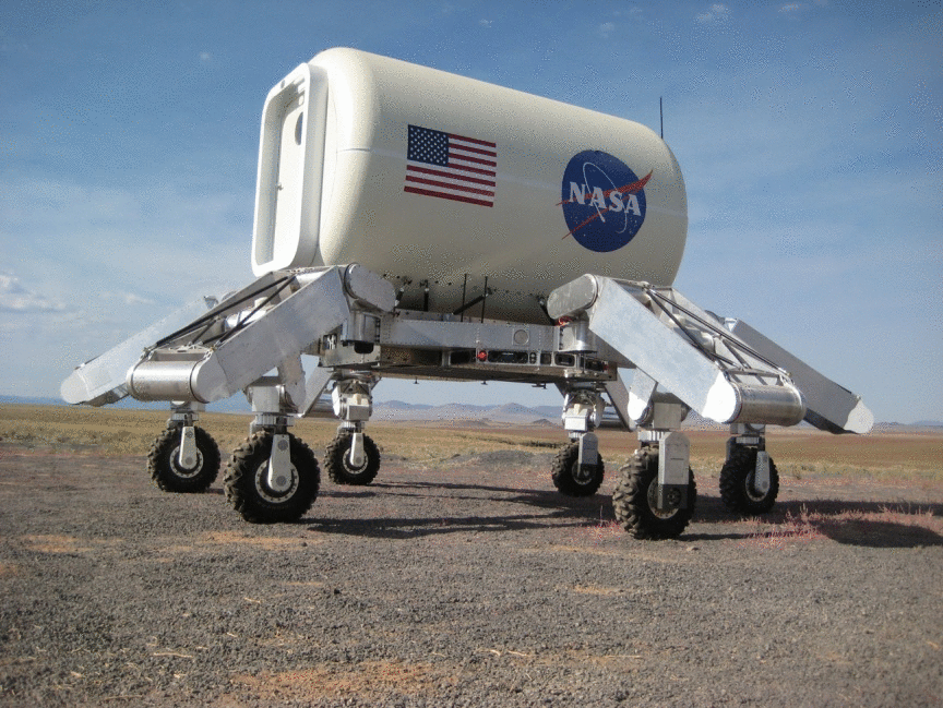 Source: Heverly [2]. Public domain (NASA / US government work).
The problem
Section titled “The problem”A lunar cargo and habitat transporter has to take a payload off a high lander deck, move it across soft regolith and rock fields, and do so within launch mass limits. The Altair descent stage carries large liquid hydrogen tanks, which puts the flat cargo deck more than 6 m above the surface, and walking cargo down from it was the task ATHLETE was built for [9], [8]. A conventional six-wheeled vehicle must be able to lift a wheel out of a hole using the rim thrust of the other five, so wheel and drive mass is set by the worst terrain. ATHLETE sizes wheels and drives for nominal terrain and uses the limbs to lift a stuck wheel, which is the mass trade the design rests on [6], [11].
The soil assumptions behind the trade are anecdotal. The 0.25 MPa per meter “4 sigma softest” lunar bearing figure is derived from the depth of Apollo boot prints, not from measurement [7]. First-generation ATHLETE accepted 20 to 45 kPa ground pressure because it can walk out of soft soil, against about 7 kPa for the Apollo rover [1].
What has flown
Section titled “What has flown”ATHLETE has not flown. All published results are terrestrial. The record is a sequence of ground prototypes.
First generation, 2005 to 2008. Two Software Development Models were built in a design, build and test cycle that began in March 2005, with the first vehicle operational that October [1]. Each is an 850 kg vehicle with a 2.75 m hexagonal frame and six 6-DOF limbs, carrying about 250 kg of payload on Earth; 36 joints share one 120 W motor and gearhead family, with overall ratios of 3,640:1 to 13,100:1 [1]. Mojave Desert and Meteor Crater tests confirmed power-efficient rolling and tool use from the wheel-driven quick-disconnect adapter [6]. At Moses Lake in June 2008 two vehicles carried graphite micro-habitat mockups 2.34 m in diameter and 3.66 m long, mated hatches to within a few millimeters in 25 to 40 minutes with a 5 to 10 s command delay, and accumulated almost 9 km of traverse with a longest single drive of 1.8 km [7].
Tri-ATHLETE SDM-T12, 2009 to 2010. The second generation is two 720 kg three-limbed vehicles that dock either side of a cargo pallet, 4.1 m tall at full extension, with 500 kg combined payload on Earth and a seventh thigh-pitch joint added to offload cargo from a 3.2 m mock lander deck [2]. In September 2009 a three-week trial at Black Point Lava Flow demonstrated that offload, walking over obstacles more than 1 m tall, backhoe excavation and more than 6 km of traverse [2]. The 2010 campaign at Hahamongna Watershed Park and Black Point covered 82.5 km in eight weeks, 23.1 km and 59.8 km at the two sites, and reached a simulated outpost in four days at over 5 km per day against a 20 km in seven days milestone [4].
Traverse was limited by operations. More than 30 percent of traverse time was idle on the best Black Point day and typically over 40 percent, with ground speeds mostly 0.5 to 3 km/h against a 3 km/h nominal design speed [4], [2]. Repeated heading commands and joystick jitter, short drives caused by steering difficulty with the handheld PortOps controller, accounted for more than half of all drive terminations; the author concludes the operator interface, not the hardware, was the binding constraint [5]. Active limb compliance held wheel normal forces evenly distributed across six limbs, using a force estimate with an error of about 100 N [4].
Low-gravity emulation, 2011 to 2013. Suspended from six computer-controlled winches with ankle force-torque sensing driving the winch dynamics, the vehicle performed a simulated 5 microgee hop of almost 2 m and an auger anchoring test in soft simulant that ended when the bin ran out of depth [11]. A later paper reports a 20 milligee landing and bounce on a mock asteroid in the same testbed [12]. Both are photographic or qualitative results [11].
What is being tried now
Section titled “What is being tried now”ATHLETE-derived concepts. Mobile in-situ resource utilization (ISRU) and construction on the limbed platform is a concept: a microwave volatile extraction plant, freeform additive construction and swappable excavation tools on the tool adapters, none built or tested [3]. The mass argument has been formalized in a parametric model that finds ATHLETE saves only 2 to 5 percent over rocker-bogie at the low end of the mass range and pulls ahead only above a few tonnes; it has not been checked against the mass of a built vehicle [12]. Funding context for the original Altair-era architecture has ended, so the lander-offload case is historical [8].
Dedicated excavators. The alternative to a walking transporter is a small rigid-wheeled vehicle that avoids the traction problem by changing the task. The ISRU Pilot Excavator (IPEx) uses one common actuator design for wheel, arm and bucket drum, and its Technology Readiness Level 5 qualification covered mobility, cameras, dust mitigation and thermal control, a ground campaign [15]. A 3D-printed bucket drum tool for the MoonBot modular rover measured 777.54 kg/h continuous excavation in quartz sand at Earth gravity, not regolith simulant [16]. Neither concept has flown.
Teach and repeat for cargo routes. Repeating a taught route between a lander and a habitat is the autonomy that would replace ATHLETE’s joystick driving. A Doppler lidar teach-and-repeat pipeline with a degeneracy-aware localizer completed all trials on featureless routes where the variants without it did not, on a wheeled terrestrial vehicle with three trials per route [24]. It is a ground test, not flight.
Legged and hopping robots in low gravity. Reinforcement learning policies for walking, vertical and forward jumping and in-flight attitude control were trained for a 14.5 kg quadruped under Mars gravity; in simulation they reach 3.1 m vertical and 3.9 m forward jumps, but only the attitude policy was transferred to hardware [19]. A proprioceptive hybrid internal model for continuous pronking under lunar gravity was tested on a gravity-offload rig [20]. A planar model and reaction-wheel controller for an underactuated bipedal hopper was evaluated only in simulation at lunar gravity [21]. A simulation study of a 24 kg quadruped on downhill ramps under lunar gravity finds torso sliding more efficient than walking above a crossover slope of 4 to 10 degrees [22]. A 9.7 kg limbed climbing robot with spine grippers has made teleoperated climbing trials on lava rock under 1 g [18]. The LASSIE program uses leg force sensing on legged robots to characterize regolith strength, verified in the lab and at White Sands and Mount Hood [17]. All of these are ground tests or simulation.
Wheel and terramechanics modeling. A resistive-force-theory model selected the grouser geometry of the LEV-1 hopping rover wheel, which then operated on the Moon after the January 2024 landing of SLIM, the one lunar-surface result in this list [27]. A variable-height grouser wheel was evaluated in 750 gantry trials on a single wheel geometry and load [26]. An open tradespace toolkit evaluates sub-50 kg lunar rovers in about 30 ms per mission and is simulation only [25]. NASA’s consolidation of mobility test practice sets out full-vehicle and single-wheel drawbar pull, slope and obstacle methods, with LTV as the case study; it reports recommendations, not new measurements [23].
Reduced-gravity testing of mobility. Parabolic flight campaigns on a single-wheel testbed found that matching wheel load alone overstates mobility, with drawbar pull to weight lower by 20 percent or more and sinkage up to 40 percent greater in lunar gravity at equal load [14].
The numbers
Section titled “The numbers”| Parameter | Value | Source |
|---|---|---|
| First-generation vehicle mass | about 850 kg | [1] |
| First-generation frame | hexagonal, 2.75 m tip to tip | [1] |
| First-generation limb length, wheel diameter | 1.8 m, 0.5 m (later Wilcox papers give 0.71 m) | [1], [6] |
| First-generation wheel motor | 730 W | [1] |
| First-generation payload, Earth gravity | 250 kg | [1] |
| Tri-ATHLETE half mass | 720 kg | [2] |
| Combined Tri-ATHLETE payload, Earth gravity | 500 kg | [2] |
| Tri-ATHLETE height, full extension | 4.1 m | [2] |
| Nominal driving speed | 3 km/h | [2] |
| Avionics battery | four cells in series, 51.2 V, 130 Ah, 78 kg | [2] |
| Processors | four 800 MHz PowerPC computers per half | [2] |
| Michelin Lunar Wheel | 71 cm by 23 cm, 15 kg, 2500 N nominal and 4500 N maximum load, 10 km/h | [2] |
| Wheel life under load in liquid nitrogen | more than 5,000 km (supplier-run) | [2] |
| 2010 traverse | 82.5 km, 23.1 km and 59.8 km at the two sites | [4] |
| Idle fraction of traverse time | over 30 percent, typically over 40 percent | [4] |
| Mobility mass fraction, Mars and lunar gravity | 20 to 25 percent and 12 to 15 percent | [12] |
| Lunar mobility mass relative to payload | 15 to 20 percent (scaling estimate) | [2] |
Joint capability, Tri-ATHLETE [2]:
| Joint | Overall gear ratio | Harmonic drive | Ratchet torque | No-load speed |
|---|---|---|---|---|
| Hip yaw | 6,591:1 | CSG-40-80 | 3,600 Nm | 0.16 rad/s |
| Hip pitch | 6,480:1 | CSG-58-80 | 10,000 Nm | 0.11 rad/s |
| Thigh pitch | 6,480:1 | CSG-58-80 | 10,000 Nm | 0.11 rad/s |
| Knee pitch | 3,240:1 | CSG-40-80 | 3,600 Nm | 0.22 rad/s |
| Knee roll | 3,514:1 | CSG-32-50 | 1,200 Nm | 0.30 rad/s |
| Ankle pitch | 6,591:1 | CSG-32-80 | 1,800 Nm | 0.16 rad/s |
| Ankle roll | 3,514:1 | CSG-32-50 | 1,200 Nm | 0.30 rad/s |
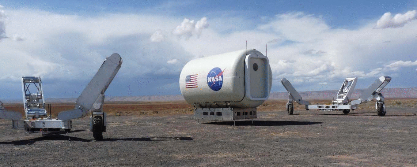 Source: Heverly [2]. Public domain (NASA / US government work).
Each joint is a brushless motor with brake and incremental encoder, a planetary stage and a harmonic drive; the ratchet torque of the harmonic drive acts as the mechanical fuse, with structure sized above it [2]. Joint torque is inferred from the difference between motor-side and output-side encoders and a measured torsional stiffness, and the six torques resolve the wrench at the wheel [1]. Ankle pitch backlash corrupted this estimate on the second-generation vehicle until the joint was redesigned [4].
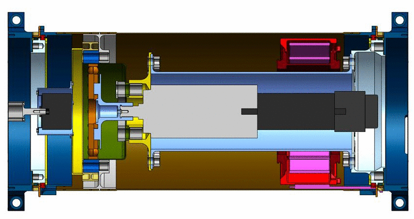 Source: Heverly [2]. Public domain (NASA / US government work).
What is not established
Section titled “What is not established”No mobility, traction or slope measurements exist for the first-generation vehicle; its 10 km/h top speed, 250 kg payload and 20 to 45 kPa ground pressure are design values, and the torque estimate accuracy is not quantified [1]. The Tri-ATHLETE field trial reports capability demonstrations, not drawbar pull, slip, sinkage or power curves, and the Michelin wheel life figure is a supplier test not independently verified [2]. The 2010 traverse was on graded dirt and lava flow at 1 g with no soil characterization, no walking, and mostly local operation with an operator alongside, so it does not represent remotely operated or lunar performance [4]. Remote operation was too rare to characterize behavior under communication delay, and the proposed interface fixes were not evaluated [5]. The 15 to 20 percent lunar mass fraction is a scaling estimate with no reduced-gravity test behind it [2], and the parametric mass model is not validated against a built ATHLETE [12]. The low-gravity winch hop is qualitative, with no repeatability or validation of the emulated dynamics [11]. The reduced-gravity wheel result [14] indicates 1 g field mobility figures do not transfer directly to the Moon. No thermal design values are published, and the 7075-T6 aluminum structure is acknowledged as unsuitable for the lunar thermal environment [2]. The legged and hopping results above are simulation or 1 g hardware tests, and the IPEx qualification is also 1 g and ground based [15].
References
- Heverly, M. (2008). A wheel-on-limb rover for lunar operations
. JPL Open Repository. Source
BibTeX
@inproceedings{heverly2008wheel, title = {A wheel-on-limb rover for lunar operations}, author = {Heverly, Matthew}, publisher = {JPL Open Repository}, year = {2008}, url = {https://dataverse.jpl.nasa.gov/dataset.xhtml?persistentId=hdl:2014/41284} } - Heverly, M., Matthews, J., Frost, M. and McQuin, C. (2010). Development of the Tri-ATHLETE Lunar Vehicle Prototype
. Aerospace Mechanisms Symposium, NASA/CP--216272. Source
BibTeX
@inproceedings{heverly2010development, title = {Development of the Tri-ATHLETE Lunar Vehicle Prototype}, author = {Heverly, Matt and Matthews, Jaret and Frost, Matt and McQuin, Chris}, booktitle = {Aerospace Mechanisms Symposium, NASA/CP--216272}, pages = {317--326}, year = {2010}, url = {https://ntrs.nasa.gov/citations/20100021930}, abstract = {The Tri-ATHLETE (All Terrain Hex Limed Extra Terrestrial Explorer) vehicle is the second generation of a wheel-on-limb vehicle being developed to support the return of humans to the lunar surface. This paper describes the design, assembly, and test of the Tri-ATHLETE robotic system with a specific emphasis on the limb joint actuators. The design and implementation of the structural components is discussed, and a novel and low cost approach to approximating flight-like cabling is also presented. The paper concludes with a discussion of the "second system effect" and other lessons learned as well as results from a three week long field trial of the vehicle in the Arizona desert.} } - Howe, A. S., Wilcox, B., Barmatz, M. and Voecks, G. (2017). ATHLETE as a Mobile ISRU and Regolith Construction Platform
. ASCE Earth and Space Conference. Source
BibTeX
@inproceedings{howe2017athlete, title = {ATHLETE as a Mobile ISRU and Regolith Construction Platform}, author = {Howe, A. Scott and Wilcox, Brian and Barmatz, Martin and Voecks, Gerald}, booktitle = {ASCE Earth and Space Conference}, pages = {560-575}, year = {2017}, doi = {10.1061/9780784479971.053}, abstract = {The all-terrain hex-limbed extra-terrestrial explorer (ATHLETE) robotic mobility platform can provide precision positioning and mobility for site preparation and regolith construction needs. ATHLETE is a multi-use platform designed to use swap-out tools and implements that can be applied to any number of tasks that need precision limb manipulation or mobility. Major capabilities include off-loading habitats, transporting surface assets, robotically assembling outposts from multiple mission manifests, and supporting science and technology objectives. This paper describes conceptual approaches for supporting NASA regolith construction research, such as additive construction, modular brick and panel factory, and mobile ISRU platform.} } - Townsend, J. (2011). ATHLETE mobility performance in long-range traverse
. AIAA SPACE Conference. Source
BibTeX
@inproceedings{townsend2011athlete, title = {ATHLETE mobility performance in long-range traverse}, author = {Townsend, Julie}, booktitle = {AIAA SPACE Conference}, publisher = {American Institute of Aeronautics and Astronautics}, year = {2011}, doi = {10.2514/6.2011-7109}, abstract = {The All-Terrain Hex-Limbed Extra-Terrestrial Explorer (ATHLETE) is a modular mobility and manipulation platform being developed to support NASA operations in a variety of missions, including exploration of planetary surfaces. The agile system consists of a symmetrical arrangement of six limbs, each with seven articulated degrees of freedom and a powered wheel. This design enables transport of bulky payloads over a wide range of terrains and is envisioned as a tool to mobilize habitats, power-generation equipment, and other supplies for long-range exploration and outpost construction.} } - Townsend, J. and Mittman, D. (2012). Driving ATHLETE: Analysis of Operational Efficiency
. AIAA SPACE Conference. Source
BibTeX
@inproceedings{townsend2012driving, title = {Driving ATHLETE: Analysis of Operational Efficiency}, author = {Townsend, Julie and Mittman, David}, booktitle = {AIAA SPACE Conference}, year = {2012}, doi = {10.2514/6.2012-5116}, abstract = {The All-Terrain Hex-Limbed Extra-Terrestrial Explorer (ATHLETE) is a modular mobility and manipulation platform being developed to support NASA operations in a variety of missions, including exploration of planetary surfaces. The agile system consists of a symmetrical arrangement of six limbs, each with seven articulated degrees of freedom and a powered wheel. This design enables transport of bulky payloads over a wide range of terrain and is envisioned as a tool to mobilize habitats, power-generation equipment, and other supplies for long-range exploration and outpost construction. In FY2010, ATHLETE traversed more than 80 km in field environments over eight weeks of testing, demonstrating that the concept is well suited to long-range travel. Although ATHLETE is designed to travel at speeds of up to 5 kilometers per hour, the observed average traverse rate during field-testing rarely exceeded 1.5 kilometers per hour. This paper investigates sources of inefficiency in ATHLETE traverse operations and identifies targets for improvement of overall traverse rate.} } - Wilcox, B. H. (2007). ATHLETE: A Mobility and Manipulation System for the Moon
. IEEE Aerospace Conference. Source
BibTeX
@inproceedings{wilcox2007mobility, title = {ATHLETE: A Mobility and Manipulation System for the Moon}, author = {Wilcox, Brian H.}, booktitle = {IEEE Aerospace Conference}, pages = {1-10}, year = {2007}, doi = {10.1109/aero.2007.352726}, abstract = {A robotic vehicle called ATHLETE - the all-terrain, hex-limbed, extra-terrestrial explorer is described, along with initial results of field tests of two prototype vehicles. This vehicle concept is capable of efficient rolling mobility on moderate terrain and walking mobility on extreme terrain. Each limb has a quick-disconnect tool adapter so that it can perform general-purpose handling, assembly, maintenance, and servicing tasks using any or all of the limbs.} } - Wilcox, B. H. (2009). ATHLETE: A Cargo and Habitat Transporter for the Moon
. IEEE Aerospace Conference. Source
BibTeX
@inproceedings{wilcox2009cargo, title = {ATHLETE: A Cargo and Habitat Transporter for the Moon}, author = {Wilcox, Brian H.}, booktitle = {IEEE Aerospace Conference}, pages = {1-7}, year = {2009}, doi = {10.1109/aero.2009.4839568}, abstract = {As part of the NASA Exploration Technology Development Program, the Jet Propulsion Laboratory is developing a vehicle called ATHLETE: the all-terrain hex-limbed extra-terrestrial explorer. The vehicle concept is based on six wheels at the ends of six multi-degree-of-freedom limbs. Because each limb has enough degrees of freedom for use as a general-purpose leg, the wheels can be locked and used as feet to walk out of excessively soft or other extreme terrain. Since the vehicle has this alternative mode of traversing through (or at least out of) extreme terrain, the wheels and wheel actuators can be sized only for nominal terrain. There are substantial mass savings in the wheels and wheel actuators associated with designing for nominal instead of extreme terrain. These mass savings are comparable-to or larger-than the extra mass associated with the articulated limbs. As a result, the entire mobility system, including wheels and limbs, can be about 25% lighter than a conventional mobility chassis for planetary exploration. A side benefit of this approach is that each limb has sufficient degrees-of-freedom for use as a general-purpose manipulator (hence the name ldquolimbrdquo instead of ldquolegrdquo). Our prototype ATHLETE vehicles have quick-disconnect tool adapters on the limbs that allow tools to be drawn out of a ldquotool beltrdquo and maneuvered by the limb. A rotating power-take-off from the wheel actuates the tools, so that they can take advantage of the 1+ horsepower motor in each wheel to enable drilling, gripping or other power-tool functions.} } - Wilcox, B. H. (2010). ATHLETE: Lunar Cargo Handling for International Lunar Exploration
. AIAA SPACE Conference. Source
BibTeX
@inproceedings{wilcox2010athlete, title = {ATHLETE: Lunar Cargo Handling for International Lunar Exploration}, author = {Wilcox, Brian H.}, booktitle = {AIAA SPACE Conference}, year = {2010}, url = {https://ntrs.nasa.gov/citations/20150008942}, abstract = {As part of the Human-Robot Systems Project within the NASA Exploration Technology Development Program, the Jet Propulsion Laboratory is developing a vehicle called ATHLETE: the All-Terrain Hex-Limbed Extra-Terrestrial Explorer. The basic idea of ATHLETE is to have six relatively small wheels on the ends of legs. The small wheels and associated drive actuators are much less massive than the larger wheels and gears needed for an "all terrain" vehicle that cannot "walk" out of extreme terrain. The mass savings for the wheels and wheel actuators is greater than the mass penalty of the legs, for a net mass savings. Starting in 2009, NASA became engaged in detailed architectural studies for international discussions with the European Space Agency (ESA), the Japanese Space Agency (JAXA), and the Canadian Space Agency (CSA) under the auspices of the International Architecture Working Group (IAWG). ATHLETE is considered in most of the campaign options considered, providing a way to offload cargo from large Altair-class landers (having a cargo deck 6+ meters above the surface) as well as offloading international landers launched on Ariane-5 or H-2 launch vehicles. These international landers would carry provisions as well as scientific instruments and/or small rovers that would be used by international astronauts as part of an international effort to explore the moon.Work described in this paper includes architectural studies in support of the international missions as well as field testing of a half-scale ATHLETE prototype performing cargo offloading from a lander mockup, along with multi-kilometer traverse, climbing over greater than 1 m rocks, tool use, etc.} } - Wilcox, B. H. (2010). ATHLETE: Lunar Cargo Unloading from a High Deck
. IEEE Aerospace Conference. Source
BibTeX
@inproceedings{wilcox2010lunar, title = {ATHLETE: Lunar Cargo Unloading from a High Deck}, author = {Wilcox, Brian H.}, booktitle = {IEEE Aerospace Conference}, pages = {1-9}, year = {2010}, doi = {10.1109/aero.2010.5446750}, abstract = {As part of the NASA Exploration Technology Development Program, the Jet Propulsion Laboratory is developing a vehicle called ATHLETE: the All-Terrain Hex-Limbed Extra-Terrestrial Explorer. Each vehicle is based on six wheels at the ends of six multi-degree-of-freedom limbs. Because each limb has enough degrees of freedom for use as a general-purpose leg, the wheels can be locked and used as feet to walk out of excessively soft or other extreme terrain. Since the vehicle has this alternative mode of traversing through or at least out of extreme terrain, the wheels and wheel actuators can be sized for nominal terrain. There are substantial mass savings in the wheel and wheel actuators associated with designing for nominal instead of extreme terrain. These mass savings are at least comparable-to or larger-than the extra mass associated with the articulated limbs. As a result, the entire mobility system, including wheels and limbs, can be lighter than a conventional all-terrain mobility chassis. A side benefit of this approach is that each limb has sufficient degrees-of-freedom to be used as a general-purpose manipulator (hence the name ¿limb¿ instead of ¿leg¿). Our prototype ATHLETE vehicles have quick-disconnect tool adapters on the limbs that allow tools to be drawn out of a ¿tool belt¿ and maneuvered by the limb. A power-take-off from the wheel actuates the tools, so that they can take advantage of the 1+ horsepower motor in each wheel to enable drilling, gripping or other power-tool functions.} } - Wilcox, B. H. (2011). ATHLETE: A Limbed Vehicle for Solar System Exploration
. IEEE Aerospace Conference. Source
BibTeX
@inproceedings{wilcox2011limbed, title = {ATHLETE: A Limbed Vehicle for Solar System Exploration}, author = {Wilcox, Brian H.}, booktitle = {IEEE Aerospace Conference}, pages = {1-9}, year = {2011}, doi = {10.1109/aero.2012.6187269}, abstract = {As part of the Human-Robot Systems project funded by NASA, the Jet Propulsion Laboratory has developed a vehicle called ATHLETE: the All-Terrain Hex-Limbed Extra-Terrestrial Explorer. Each vehicle is based on six wheels at the ends of six multi-degree-of-freedom limbs. Because each limb has enough degrees of freedom for use as a general-purpose leg, the wheels can be locked and used as feet to walk out of excessively soft or other extreme terrain. Since the vehicle has this alternative mode of traversing through or at least out of extreme terrain, the wheels and wheel actuators can be sized for nominal terrain. There are substantial mass savings in the wheel and wheel actuators associated with designing for nominal instead of extreme terrain. These mass savings are comparable-to or larger-than the extra mass associated with the articulated limbs. As a result, the entire mobility system, including wheels and limbs, can be about 25% lighter than a conventional mobility chassis. A side benefit of this approach is that each limb has sufficient degrees-of-freedom to use as a general-purpose manipulator (hence the name "limb" instead of "leg"). Our prototype ATHLETE vehicles have quick-disconnect tool adapters on the limbs that allow tools to be drawn out of a "tool belt" and maneuvered by the limb. A power-take-off from the wheel actuates the tools, so that they can take advantage of the 1+ horsepower motor in each wheel to enable drilling, gripping or other power-tool functions. This paper describes the applicability of the ATHLETE concept to exploration of the moon, Mars and Near-Earth Asteroids (NEAs). Recently, the focus of human exploration beyond LEO has been on NEAs. One scenario for exploration of a NEA has been likened to a submarine exploring a wrecked ship - humans would sit in a "bubble" and approach the asteroid for up-close examination and robotic manipulation. What is important is to ensure that the bubble doesn't collide with the asteroid surface, nor float away. Multiple limbs, such as available on ATHLETE, allow for precise positioning and anchoring so as to enable the human bubble to maximize its exploration potential. A microgravity testbed has been constructed in the ATHLETE lab, with six computer-controlled winches able to lift ATHLETE and payloads so as to simulate the motion of the system in the vicinity of a NEA. Accurate 6-axis force-torque sensors will measure the applied forces and moments wherever the vehicle touches a simulated asteroid surface. These measured forces can be used to compute the resultant motion of the vehicle in the microgravity environment, and the winches then move the vehicle along the computed trajectory. Preliminary test results from this system are described.} } - Wilcox, B. H. (2013). ATHLETE: Trading Complexity for Mass in Roving Vehicles
. AIAA SPACE Conference. Source
BibTeX
@inproceedings{wilcox2013athlete,
  title = {ATHLETE: Trading Complexity for Mass in Roving Vehicles},
  author = {Wilcox, Brian H.},
  booktitle = {AIAA SPACE Conference},
  year = {2013},
  doi = {10.2514/6.2013-5382},
  abstract = {This paper describes a scaling analysis of ATHLETE for exploration of the moon, Mars and Near-Earth Asteroids (NEAs) in comparison to a more conventional vehicle configuration. Recently, the focus of human exploration beyond LEO has been on NEAs. A low gravity testbed has been constructed in the ATHLETE lab, with six computer-controlled winches able to lift ATHLETE and payloads so as to simulate the motion of the system in the vicinity of a NEA or to simulate ATHLETE on extreme terrain in lunar or Mars gravity. Test results from this system are described.}
}
Further reading
- Wilcox, B. H. (2011). ATHLETE: A Cargo-Handling Vehicle for Solar System Exploration . Aerospace Conference. Source
- (2026). NASA NTRS: ATHLETE. ntrs.nasa.gov/search