JEM Remote Manipulator System
Program pages JAXA: Remote Manipulator System, About Kibo JAXA: Major Component, About Kibo
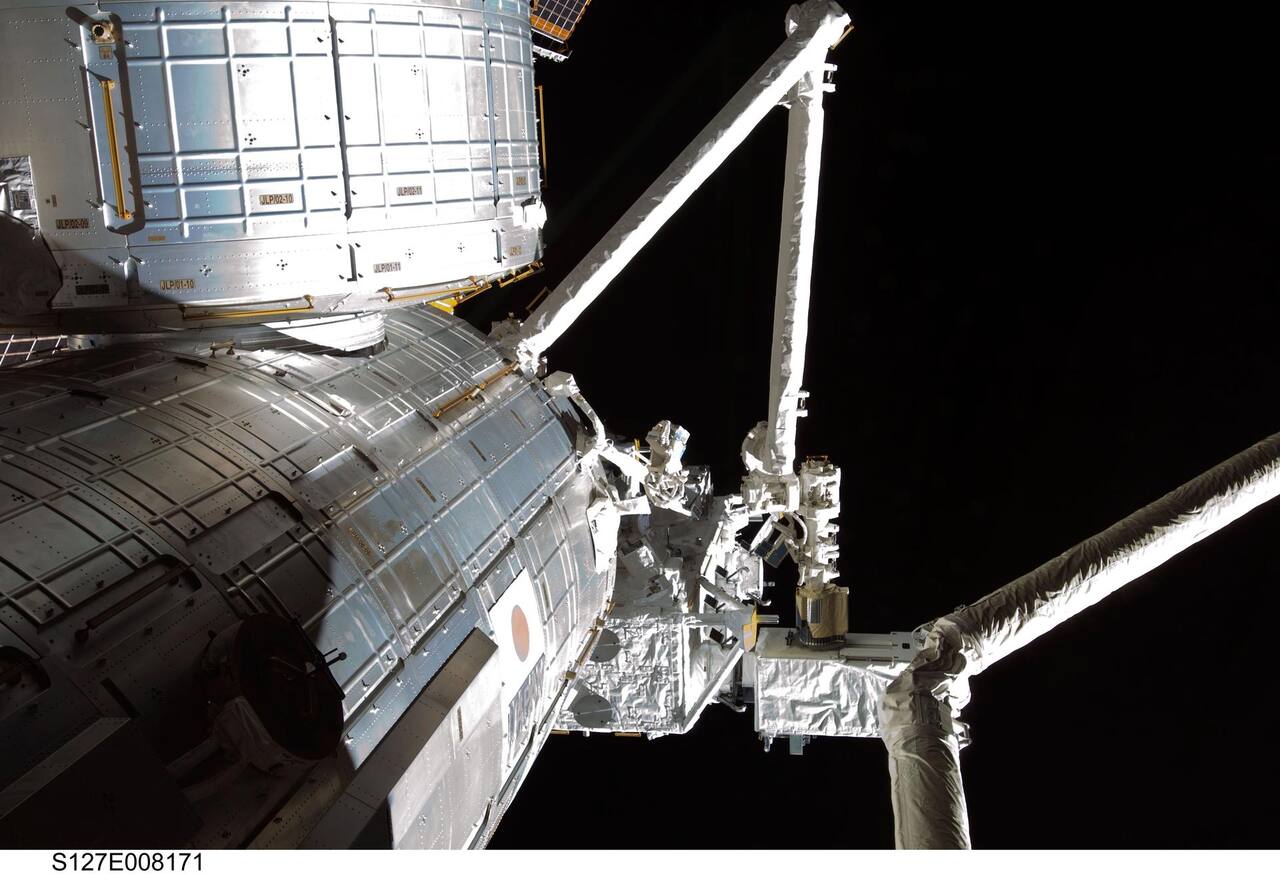 NASA. Public domain (NASA / US government work).
Overview
Section titled “Overview”The JEM Remote Manipulator System is the robotic system of Kibo, the Japanese Experiment Module of the International Space Station. It comprises two arms and a console inside the pressurized module [1]. The main arm handles payloads on the Exposed Facility, the small fine arm, and Kibo elements such as the Experiment Logistics Module Exposed Section. The small fine arm attaches to the tip of the main arm and performs dexterous work such as orbital replacement unit exchange [1], [2]. It was developed by the National Space Development Agency of Japan with Toshiba as prime contractor for the arm hardware [1], [3], and is operated by JAXA [11]. Contemporary Japanese reviews list it as the agency’s principal space robotics project of the 1990s [4].
The hardware reached the station in two flights. STS-124 in June 2008 delivered the pressurized module together with the main arm, and STS-127 in July 2009 delivered the Exposed Facility and the small fine arm, the same mission on which the arm made its first payload transfer [10]. A long-reach arm for coarse positioning carrying a small dexterous arm on its own tip parallels the pairing of Canadarm2 and Dextre on the station [9], [8].
Both arms have six degrees of freedom in an anthropomorphic layout of two shoulder joints, one elbow joint and three wrist joints [1]. The main arm carries three booms, two long booms of carbon fiber reinforced plastic chosen for low thermal expansion, high stiffness and low mass, and one short aluminum boom. The small fine arm carries two aluminum booms and is 2.2 m long and 190 kg [11]. Every joint on both arms has a brake that is active without electrical power [1].
Specifications
Section titled “Specifications”| Parameter | Main arm | Small fine arm | Source |
|---|---|---|---|
| Degrees of freedom | 6 | 6 | [1], [11] |
| Joint layout | 2 shoulder, 1 elbow, 3 wrist | 2 shoulder, 1 elbow, 3 wrist | [1] |
| Length | 10 m | 2.2 m | [11] |
| Mass | 780 kg | 190 kg | [2], [11] |
| Rated payload | 7,000 kg | 300 kg, or 80 kg under force moment accommodation | [2], [11] |
| Positioning accuracy, translation | +/-50 mm | +/-10 mm | [1], [11] |
| Positioning accuracy, rotation | +/-1 deg | +/-1 deg | [1], [11] |
| Maximum tip force | over 30 N | over 30 N | [1], [11] |
| Tip translation rate | 60 mm/s under 600 kg, 30 mm/s to 3,000 kg, 20 mm/s to 7,000 kg | 50 mm/s under 80 kg, 25 mm/s to 300 kg | [11] |
| Maximum stopping distance, translation | 300 mm | 75 mm | [1] |
| Maximum stopping distance, rotation | 5 deg | 5 deg | [1] |
| Joint output torque | about 400 N m | about 41 N m joints 1 to 3, 18 N m joints 4 to 6 | [2] |
| Joint reduction ratio | 1400:1 | 130:1 joints 1 to 3, 120:1 joints 4 to 6 | [2] |
| Joint brake torque | 150 to 270 N m | 40 to 120 N m | [2] |
| Joint rotational stiffness | about 3e5 N m/rad | 0.8e4 to 1.6e4 N m/rad | [2] |
| Joint bending stiffness | about 1e6 N m/rad | not published | [2] |
| Joint backlash | 0.043 to 0.056 deg | 0.03 to 0.06 deg | [2] |
| Housing alignment uncertainty | within 0.012 deg | 0.01 to 0.03 deg | [2] |
| Design life | over 10 years | not published | [11] |
The 1994 design specification gives lower rates than the flight figures above, with main arm translation of 10 mm/s under a 7,000 kg payload rising to 60 mm/s under 600 kg, and rotation of 0.5 deg/s under 7,000 kg rising to 2.5 deg/s under 600 kg [1]. The small fine arm design figures are 10 mm/s and 0.5 deg/s under 300 kg, and 30 mm/s and 1.0 deg/s under 130 kg.
Natural frequencies of the main arm were computed by finite element model in a near extended reference configuration with the elbow pitch joint at 150 degrees to avoid the singularity [1]. The storage configuration was chosen both to lower heater power and to raise the natural frequency above that of the reference configuration, the second consideration mattering because the arm is a 10 m, 780 kg structure [11], [2].
| Configuration | 1st mode | 2nd mode |
|---|---|---|
| On orbit, no payload | 0.32 Hz | 0.34 Hz |
| On orbit, 500 kg payload | 0.19 Hz | 0.21 Hz |
| On orbit, 7,000 kg payload | 0.046 Hz | 0.05 Hz |
| On orbit, storage configuration | 0.65 Hz | 1.01 Hz |
| Launch configuration | 14.2 Hz | 14.9 Hz |
On-orbit natural frequency is set mainly by the torsional stiffness of the joints, which is in turn set mainly by the torsional stiffness of the speed reducers [1]. Boom stiffness is much larger than joint stiffness on both arms, so the joints dominate arm compliance [2]. Later control research built on the small fine arm as a worked example of a flexible-structure manipulator, treating its joint compliance as a set of link-side flexible degrees of freedom in the arm’s equations of motion and deriving an adaptive reaction-control law to handle an unknown payload’s dynamic parameters without needing the flexibility itself to be identified in advance [7].
Mission profile
Section titled “Mission profile”| Event | Date |
|---|---|
| Three payloads assembled onto the Exposed Facility by astronaut teleoperation of the arm | 2009-07 |
| Two further payloads assembled the same way | 2009-09 |
| Exposed Pallet assembly and removal, first occasion | 2009-09 |
| Exposed Pallet assembly and removal, second occasion | 2011-02 |
Source: [6].
Through February 2011 the arm and the Exposed Facility Unit had assembled five payloads and had berthed and removed an Exposed Pallet twice, all under astronaut teleoperation [6]. The pair could not be verified together on the ground with flight hardware, because the arm cannot execute its three-dimensional motion under gravity: a hardware simulator reproducing the arm tip positioning performance supplied the basic behavior data for the coordinated operation, and a software simulator of arm motion and contact covered the off-nominal cases that cannot be reproduced on the ground. Before each payload was assembled the arm’s vision system was squared onto the vision marker of the target Exposed Facility Unit and imaged, and ground image measurement of the unit’s position found corrections from the design values larger than expected, up to 10 cm [6]. The Kibo standard payload against which the main arm was sized is 500 kg and 1 m by 1 m by 1.9 m, berthed to one of twelve Exposed Facility Units [2].
Architecture
Section titled “Architecture”The main arm consists of three booms, six joints, a base, an end effector and two vision equipment assemblies [1]. The base is titanium and carries a curvic coupling so that an EVA crew member can separate the arm from the pressurized module for maintenance. The end effector is similar to the standard end effector of the Shuttle Remote Manipulator System, and grapples the same grapple fixture interface used elsewhere on the station [1], [2]. JAXA describes it as a grapple fixture interface for Exposed Facility payloads, and the arm is rated for a design life of over ten years [11].
The small fine arm consists of two aluminum booms, six joints, an electronics unit, an end effector, a force and moment sensor and a TV camera [1]. Its end effector is a Kibo-unique device called the Tool, which grasps a Tool Fixture on the payload and supplies torque to a bolt through it [1], [2]. The prototype built for the JEM Flight Demonstration used a three-finger tool with an integrated torque driver for loosening and fastening the bolts that structurally attach an orbital replacement unit [3]. A grapple fixture on the base of the small fine arm is what the main arm holds when the small arm is in use [2].
Kibo itself comprises the pressurized module, the Exposed Facility, the Experiment Logistics Module pressurized and exposed sections, and the manipulator system [1], [12]. A tutorial survey of station manipulators groups JEMRMS with the Shuttle and space station remote manipulator systems and ETS-VII as the orbital arms whose design and control problems established the field before on-orbit servicing became a program of its own [8]. In the launch configuration the main arm is stowed on the aft end plate of the pressurized module by three hold and release mechanisms [1]. Pressurization of the module deforms it and forces a relative displacement on the stowed arm, which would induce large loads, so one of the three mechanisms carries a load relief device in the boom axial direction.
Joints and actuators
Section titled “Joints and actuators”Each of the six main arm joints is a revolute unit delivering about 400 N m of output torque from a brushless DC motor through solid lubricated gearing at 1400:1 [2]. The joint carries a magnetic resolver of 0.002 degree resolution on the motor axis and an optical absolute encoder between the inner and outer housings of 0.006 degree resolution and 0.011 degree accuracy. Main bearings are solid lubricated under constant preload, and an off-activated ceramic brake sits on the motor axis. Each joint contains a joint electronics unit that closes the angle and angular velocity loops locally [1].
The small fine arm has two sets of three identical joints, joints 1 to 3 delivering about 41 N m and joints 4 to 6 about 18 N m, each through a solid lubricated Harmonic Drive at 130:1 and 120:1 respectively [2]. Position feedback is by magnetic encoder of 0.006 degree resolution. The rated handling mass of that arm is 300 kg, falling to 80 kg when force moment accommodation is in use [11].
Back-drive torque matters for the main arm because payload mating and demating is performed by letting external force move the arm tip in a limp mode, and the resisting torque is dominated by gear friction [2]. It was measured at 10.4 to 20.3 N m in thermal vacuum and 17.5 to 39.0 N m in nitrogen gas at ambient pressure. On the small fine arm the same quantity is less important because contact operations are actively limped through the force and torque sensor, and was measured within about 10 N m for joints 1 to 3 and 8 N m for joints 4 to 6, excluding up to about 10 N m of cable loss torque in orbital conditions [2].
Force and torque sensing
Section titled “Force and torque sensing”The small fine arm carries an aluminum alloy six-axis force and torque sensor at its tip, which is what enables compliance control and active limp control [2].
| Channel | Range | Accuracy | Resolution |
|---|---|---|---|
| Force | to 10 N | about 1 N | 0.17 N |
| Force | to 60 N | about 2 N | 0.17 N |
| Moment | to 1 N m | about 0.1 N m | 0.015 N m |
| Moment | to 10 N m | about 0.3 N m | 0.015 N m |
Values from [2], measured after overload force and moment tests, against full ranges of 60 N and 9 N m. Rated tip force for both arms is over 30 N [11].
Compute and control
Section titled “Compute and control”Both arms are controlled by dual 32-bit microprocessors located in the pressurized module, communicating over dual MIL-STD-1553B networks [2]. The control algorithm is classical, using phase lead and lag filters, and the controller is closed on the motor axis rather than the output axis of the speed reducer so that joint backlash is kept outside the closed loop [1], [2]. Eight sets of control parameters are stored in each joint electronics unit and selected by the arm control unit according to the payload mass properties and the arm configuration [1]. The small fine arm additionally runs five 32-bit microprocessors in an electronics box at its base, which close the angular velocity loops of its six joints [2].
Arm performance was predicted before flight by a non-real-time computer simulator running the controller against the joint characteristics, and the mathematical model was updated from modal survey and two-dimensional flat floor function tests [1].
Autonomy
Section titled “Autonomy”The main arm is operated primarily in preprogrammed control, with manual control through the rotational and translational hand controllers as the alternative [1]; both controllers are part of the console in the pressurized module [11]. For the small fine arm manual control is primary [1]. In manual mode the crew member works from joysticks with overlay templates superimposed on the display [2].
Preprogrammed motion relies on vision to correct for misalignment. Kibo assembly tolerances and thermal distortion move the target relative to the arm base, so the position and orientation of a target are measured by the wrist vision equipment and the management data processor and fed into the preprogrammed path [1]. Visual sensing uses a three-dimensional four-point target at the worksite [2]. The crew member completes the calibration by adjusting four cursors on the screen until they overlap the four target points. Visual calibration carries many error sources and is the dominant contributor to total positioning error.
Berthing a payload to an Exposed Facility Unit follows an L-shaped approach path rather than a straight one, to avoid jamming with the capture mechanism [2]. The wrist camera pan and tilt capability exists so that the arm can be positioned at the coarse visual calibration point and then at the fine positioning point at the Payload Interface Unit even when a large payload blocks the view ahead of the arm [2].
Measured performance
Section titled “Measured performance”Positioning error of the main arm was analyzed as a total of under 44.7 mm in translation and 0.46 degrees in rotation, built from joint backlash at under 20.9 mm, housing alignment at under 16.4 mm, assembly at under 16.3 mm, control error at under 5.3 mm and thermal at under 2.2 mm [2]. Ground measurement by three-dimensional measuring equipment gave 22.9 mm in x, 54.0 mm in z and 0.71 degrees. Eliminating ground friction gives an on-orbit estimate of 14.7 mm, 29.2 mm and 0.370 degrees on output-axis encoder data [2]. The specification the arm is held to is +/-50 mm in translation and +/-1 degree in rotation [1], [11].
| Quantity | Main arm | Small fine arm |
|---|---|---|
| Positioning error, own coordinate system | under 44.7 mm, under 0.46 deg | under 2.62 mm, under 0.69 deg |
| Positioning error mounted on a servo-locked main arm | under 8.28 mm | |
| Deviation from nominal path, along path | 50.9 mm test, 52.1 mm analysis | 26.2 mm analysis |
| Deviation from nominal path, radial | 16.4 mm test, 14.3 mm analysis | 6.3 mm analysis |
| Emergency stop, 600 kg at 60 mm/s | 117.0 mm test, 129.6 mm analysis, 0.39 deg test | |
| Emergency stop, 3,000 kg at 30 mm/s | 89.5 mm test, 121.6 mm analysis, 0.51 deg test |
Source: [2].
System performance was compared between worst-case analysis and system test data taken on an air bearing floor in two-dimensional arm movement, with the small fine arm always evaluated attached to a servo-locked main arm because that is how it is used [2]. A two-dimensional flat floor test was part of the engineering model program from the outset [1], and the small fine arm was designed from the start to be carried on the main arm tip [1], [4]. Measured emergency stop distances stay inside the 300 mm and 5 degree limits set in the design specification [1].
Berthing conditions were verified against the design specification limits.
| Berthing quantity | Limit | Evaluated |
|---|---|---|
| Forward approach speed | 30 mm/s | 10 mm/s |
| Radial approach speed | 30 mm/s | |
| Rotational rate | 0.5 deg/s | |
| Effective mass at the main arm wrist | 400 kg | 320 kg |
| Attitude within the approach envelope | 3 degrees | 1.7 degrees |
| Capture wobble | 1.6 degrees | under 1.4 degrees |
| Axial capture angle | 1.2 degrees | under 0.6 degrees |
| Back-drive force, axial | 110 N | 43 N |
| Back-drive force, radial | 110 N | 72 N |
| Back-drive torque, rotational | 220 N m | 179 N m |
| Back-drive torque, wobble | 220 N m | 196 N m |
Source: [2].
Berthing is the task the arm exists to perform, since the Exposed Facility is loaded and unloaded by the arm rather than by crew [1], [11], and a failed capture would produce debris or damage station structure [2].
Cameras and vision
Section titled “Cameras and vision”The main arm carries two vision equipment assemblies, each a TV camera on a pan and tilt unit; only the wrist assembly has an arm light [1]. The wrist camera has pan, tilt, zoom, iris and focus control and provides the six-degree-of-freedom measurement used for automatic manipulation [2]. The small fine arm carries a fixed-focus camera on its wrist. Camera and light assemblies on the main arm booms are listed by JAXA as part of the delivered system [11].
Ground operations and console
Section titled “Ground operations and console”Both arms are operated by a crew member at the JEMRMS console in the pressurized module [1], [11]. The console comprises two TV monitors, passive rotational and translational hand controllers, hand controller electronics, a remote interface panel, a laptop workstation, a task light, a management data processor, a mass storage unit, an arm control unit, a power distribution box, a rack essential package, a fire detection and suppression panel, hold and release mechanism electronics, and a standard double rack [1]. NASA supplies a split screen capability that lets the operator view three video feeds simultaneously during robotic operations. Both arms are operated from the one console.
A six-degree-of-freedom orthogonal force-reflecting hand controller was developed as a prototype common master for both arms, on the argument that an orthogonal master simplifies the coordinate transformation to any slave configuration and that a single unit therefore suffices for two articulated arms of different geometry [5]. The prototype measured about 350 by 350 by 350 mm with a 150 mm cubic motion envelope and weighed 15 kg including mechanical dead weight compensation. It was tested both as a rate-control joystick and as a force-reflecting master against a six-degree-of-freedom experimental manipulator, the intent being that one master serve both the main arm and the small fine arm from the small operating compartment available. The flight console uses separate passive rotational and translational hand controllers [1].
JAXA lists the console contents as a management data processor, a laptop computer, rotational and translational hand controllers, TV monitors and hold and release electronics [11]. The console layout was itself revised during development. Termination of the multi-purpose application console in the space station redesign forced a redesign of the JEMRMS console, with its concept design review held at the end of October 1994 [1].
Verification
Section titled “Verification”Engineering model testing of the main arm was planned from summer 1995 to summer 1996 and covered function testing including a two-dimensional flat floor test, modal survey in both orbit and launch configurations, static load test, random vibration, electromagnetic compatibility and thermal balance [1]. Static load and random vibration were qualification tests. The end-to-end system test with the main arm, the console and the small fine arm was limited to the extensive function test including the two-dimensional flat floor test of the main arm carrying the small fine arm. Qualification results were later published as evidence that the design met its performance requirements [2].
Technologies developed
Section titled “Technologies developed”The JEM Flight Demonstration was a separate program to fly a prototype small fine arm in the Space Shuttle payload bay on a multi-purpose experiment support structure, operated by a crew member from a workstation on the aft flight deck, with an orbital replacement unit and a task panel as robotic targets and two camera and light assemblies for visual feedback [3]. Launch was scheduled for 1997. Its preliminary design review completed in December 1992, and phase 0 and phase 1 safety reviews were conducted against Shuttle payload safety requirements [3].
The program produced a large space manipulator built around solid lubricated gearing and bearings characterized for back-drive torque in thermal vacuum, which is the parameter that governs whether a payload can be mated by letting the arm go limp [2]; a tip-mounted six-axis force and torque sensor accurate to about 1 N and 0.1 N m that supports compliance control and force moment accommodation on a dexterous sub-arm; and the pairing of a large arm with a small dexterous arm carried on its own tip and stowed separately on an exposed facility [1]. JEMRMS is identified in contemporary reviews as one of the three Japanese space robotics projects of its era alongside the JEM Flight Demonstration and ETS-VII [4].
Place among other station manipulators
Section titled “Place among other station manipulators”JEMRMS is one of several arms built for orbital stations, and its specifications are easiest to read against the others. The Shuttle arm it descends from was specified for a 65,000 lbm payload at 2 in and 1 deg tip positioning [14]. The station arm Canadarm2 has seven joints in a roll, yaw, pitch, pitch, pitch, yaw, roll sequence, all identical at plus or minus 270 deg travel [13]. JEMRMS has six joints and no kinematic redundancy [1], so it lacks the extra joint [13] describes. Canadian design documentation separates the two failure philosophies, fail operational for the large arm and fail safe for Dextre, and gives the Space Vision System a role in the large arm’s visual reference [13]. CSA publishes a data sheet for Canadarm2 and a landing page for Dextre, the special purpose dexterous manipulator that fills a role comparable to the small fine arm [17], [18].
The European Robotic Arm is the closest large-arm counterpart. It is 11.3 m long with seven degrees of freedom and 630 kg, rated for 8,000 kg moveable mass, with plus or minus 40 mm open loop and plus or minus 5 mm closed loop accuracy as specification values written before launch [15]. ESA states that Canadarm2 and JEMRMS cannot serve the Russian segment because the base point and payload mounting interfaces differ [16]. The Chinese station carries a 7 degree of freedom, 10 m core module manipulator [19] and a small arm, 14 degrees of freedom when the two are combined through an adapter [28]. NASA’s servicing catalog gives no sources for its Chinese arm figures [19], and a 2024 survey of on-orbit servicing manipulators compiles arm specifications from vendor and agency sources without measurement conditions [20]. No source held here compares on-orbit accuracy across these arms.
NASA’s servicing catalog divides manipulators into long and short reach at 8 m [19]. By that threshold the 10 m main arm is long reach and the 2.2 m small fine arm is short reach, which matches the coarse and fine pairing of the Canadian arm and Dextre [13], [18].
Work on the Chinese station arms is the most recent counterpart. On 6 January 2022 the Chinese station arm unlocked the Tianzhou-2 cargo craft and transferred it, which Xinhua reported as the first use of a station arm to move a large spacecraft [42]. A closed form inverse kinematics solution exists for the offset shoulder roll, yaw, pitch geometry shared by Canadarm2 and the Chinese arm [40], and a screw theory model of the Wentian arm solves inverse kinematics by fixing one joint pair at a time [44]. The six-axis force and torque sensor of the Experimental Module Manipulator is ranged at plus or minus 500 N and plus or minus 100 N m and went through space environment qualification [41]. A review of on-orbit servicing lists the Shuttle, station and Kibo arms among the robotic arms flown to date [39]. A survey by groups who built capture systems organizes manipulation and capture of a target into four phases, and is the reference for what a station arm does not yet do autonomously [43]. These are design and ground results except for the 2022 transfer [42].
Flown Japanese precursors
Section titled “Flown Japanese precursors”Two Japanese experiments exercised orbital manipulation before JEMRMS reached the station. The JEM Flight Demonstration of the small fine arm on the Shuttle was planned and did not fly in the configuration described [3]. ETS-VII did fly: its three autonomous docking experiments between July 1998 and October 1999 reached 7 mm lateral position error against a 25 mm requirement, always against a cooperative target [30]. On 22 November 1999 its arm was teleoperated from the ground under direct bilateral force coupling with a 6 to 7 s round trip delay, which the authors describe as possible but not shown to be practical, from one to three runs per condition [31]. JEMRMS itself is operated by a crew member at the console rather than from the ground [1], [11].
Actuators and flexibility in related work
Section titled “Actuators and flexibility in related work”The JEMRMS joint choices, solid lubricated gearing at 1400:1 on the main arm and Harmonic Drives at 130:1 and 120:1 on the small fine arm [2], follow a design question the Shuttle arm answered differently. The Shuttle arm joints use two gear trains in series at about 738:1 at the wrist drives and 1842:1 at the shoulder [21]. The same survey reports that harmonic drives need about 30 percent extra torque to overcome static friction and drop from 80 to 90 percent efficiency with wet lubricant to as low as 50 percent dry, figures drawn from the authors’ own earlier tests with no stated conditions [21]. Harmonic drives were later used on the Mars Exploration Rovers, 19 actuators characterized in ground thermal chamber tests from +25 to -70 degrees C on non-flight engineering units [22]. Neither source measured the drives under the thermal vacuum conditions in which the JEMRMS back-drive torque figures were taken.
Joint compliance dominates JEMRMS arm compliance [2], which links it to the modeling and control literature on flexible arms. A modal admittance model of the Shuttle arm in four brake-locked configurations found that four to six retained modes were needed in the unloaded case and 15 to 20 with a 1,000 lb payload [23]; that model is analytical, with no comparison against measured arm flexibility. The small fine arm is likewise always used on a servo-locked main arm [2]. Reaction null-space control of a rigid manipulator on a flexible base was demonstrated on a planar two-link arm mounted on a double beam in one gravity [24], without tabulated suppression figures. Configuration-dependent vibration controllability was shown analytically and on the FLEBOT II rig, where some configurations cannot control a mode [25]. A predictive and inverse scheme for flexible macro and rigid micro manipulators was evaluated in simulation only [26], and a macro and micro testbed with a 3.4 m flexible beam cut shoulder slew settling time by 97 percent with inertial damping on that bench [29]. The macro-micro arrangement is the same structure as the small fine arm on the main arm tip. None of these was flown on JEMRMS.
Ground simulation of microgravity is the standard substitute for verification, and JEMRMS used a two-dimensional air bearing floor [2]. A three-dimensional free-motion simulator built from stacked air bearings reported vertical suspension friction of 0.1 N but only a 0.2 m vertical stroke [27]. NASA’s air bearing floor at Johnson is 21.3 by 29.9 m [20].
What is being tried now
Section titled “What is being tried now”None of the following has flown on JEMRMS. They are grouped by what they address.
Crew-operated dexterous robots on the station. Robonaut 2 operated stationary on the station for more than two years by 2013, running checkout operations, task-board work on switches, connectors and valves, and two air flow meter tasks, and in April 2013 was teleoperated on orbit by a crew member in a tracker vest and VR helmet [32]. The status report gives no success rates or positioning accuracy. It is flight experience with a dexterous robot on the same station.
Crew control of a ground robot from the station. Three Expedition 36 astronauts operated the K10 rover in a lunar analog yard over 11 hours across three sessions in 2013, with 65 to 80 percent rover utilization, link outages of up to 35 percent of a phase excluded from that figure, and latency of 1 to 2 s through the station Ku-band link [33]. The sample is three subjects with one session each, so the authors give no statistical result. The robot stood in a yard on Earth, not on orbit.
Servicing-arm technology. A 2014 review of on-orbit servicing robotics covers free-floating manipulator kinematics, target motion estimation, capture, post-capture stabilization, flexible-arm vibration suppression and ground test facilities, and notes that no fully autonomous servicing of a non-cooperative target had been demonstrated [34]. Grapple-contact excitation of a client satellite’s flexible appendages has been modeled with a reduced-order real-time model of a satellite with one or two appendages, with first-mode correlation off by 20 percent in deformed amplitude and 1 percent in frequency [38]. The model is analytical [38].
Adaptive control of uncertain and flexible arms. An adaptive reaction null-space controller for free-floating manipulators with uncertain kinematics and dynamics was shown on a planar 3-DOF model in simulation only [36]. A direct adaptive composite controller for a two-link manipulator with nonlinear flexible joints, including soft windup and friction, was likewise simulated only, with joint stiffness taken from an earlier paper [37]. Both address the joint compliance that dominates JEMRMS arm compliance [2], and neither has hardware results [36], [37].
Competing station arms. The Chinese station manipulator developers compare their design with the station arm, JEMRMS and the European arm in a pre-flight paper whose design values differ slightly from final flown values [35].
What is not established
Section titled “What is not established”The published error budget and back-drive torque figures come from ground qualification and a two-dimensional flat floor rig, not from an on-orbit measurement of the same quantities under zero gravity [2]. The 10 cm berthing-target position corrections found during actual operations are the only on-orbit accuracy figure held here, and they are task-specific to Exposed Facility Unit alignment rather than a general figure for arm positioning error [6]. The adaptive control law developed around the small fine arm’s flexible joints is a simulation study of the arm’s dynamics, not a flight-tested controller, and nothing held here shows whether JAXA adopted anything like it for operations [7]. No source held here gives an operational history of the arm beyond February 2011, and the arm’s performance across the remaining service life of Kibo is not established.
The comparative figures for the European and Chinese arms are design specifications or catalog entries [15], [19], and no source held here compares their on-orbit accuracy with the JEMRMS figures. The related flexible-arm control studies are ground or simulation work [24], [26], and the ETS-VII results come from a different arm on a free-flying satellite [30], [31].
References
- Matsueda, T., Kuwao, F., Motohashi, S. and Okamura, R. (1994). Development of Japanese Experiment Module Remote Manipulator System
. International Symposium on Artificial Intelligence, Robotics and Automation in Space. Source
BibTeX
@inproceedings{matsueda1994development, title = {Development of Japanese Experiment Module Remote Manipulator System}, author = {Matsueda, Tatsuo and Kuwao, Fumihiro and Motohashi, Shoichi and Okamura, Ryo}, booktitle = {International Symposium on Artificial Intelligence, Robotics and Automation in Space}, pages = {183--186}, year = {1994}, url = {https://ntrs.nasa.gov/citations/19950017288}, abstract = {National Space Development Agency of Japan (NASDA) is developing the Japanese Experiment Module (JEM), as its contribution to the International Space Station. The JEM consists of the pressurized module (PM), the exposed facility (EF), the experiment logistics module pressurized section (ELM-PS), the experiment logistics module exposed section (ELM-ES) and the Remote Manipulator System (RMS). The JEMRMS services for the JEM EF, which is a space experiment platform, consists of the Main Arm (MA), the Small Fine Arm (SFA) and the RMS console. The MA handles the JEM EF payloads, the SFA and the JEM element, such as ELM-ES.} } - Wakabayashi, Y., Morimoto, H., Satoh, N., Hayashi, M., Aiko, Y. and Suzuki, M. (2002). Performance of Japanese Robotic Arms of the International Space Station
. International Federation of Automatic Control Triennial World Congress. Source
BibTeX
@inproceedings{wakabayashi2002performance, title = {Performance of Japanese Robotic Arms of the International Space Station}, author = {Wakabayashi, Y. and Morimoto, H. and Satoh, N. and Hayashi, M. and Aiko, Y. and Suzuki, Mineo}, booktitle = {International Federation of Automatic Control Triennial World Congress}, volume = {35}, pages = {115-120}, year = {2002}, doi = {10.3182/20020721-6-es-1901.00925} } - Nagatomo, M., Tanaka, M., Nakamura, K. and Tsuda, S. (1994). Space Robotic Experiment in JEM Flight Demonstration
. International Symposium on Artificial Intelligence, Robotics and Automation in Space. Source
BibTeX
@inproceedings{nagatomo1994space, title = {Space Robotic Experiment in JEM Flight Demonstration}, author = {Nagatomo, Masanori and Tanaka, Masaki and Nakamura, Kazuyuki and Tsuda, Shinichi}, booktitle = {International Symposium on Artificial Intelligence, Robotics and Automation in Space}, pages = {149--152}, year = {1994}, url = {https://ntrs.nasa.gov/citations/19950017281}, abstract = {Japan is collaborating on the multinational space station program. The JEM, Japanese Experiment Module, has both a pressurized module and an Exposed Facility (EF). JEM Remote Manipulator System (JEMRMS) will play a dominant role in handling/servicing payloads and the maintenance of the EF, and consists of two robotic arms, a main arm and a small fine arm. JEM Flight Demonstration (JFD) is a space robotics experiment using the prototype small fine arm to demonstrate its capability, prior to the Space Station operation. The small fine arm will be installed in the Space Shuttle cargo bay and operated by a crew from a dedicated workstation in the Aft Flight Deck of the orbiter.} } - Ohkami, Y., Nakatani, I., Wakabayashi, Y. and Iwata, T. (1994). A Perspective on Space Robotics in Japan
. International Symposium on Artificial Intelligence, Robotics and Automation in Space. Source
BibTeX
@inproceedings{ohkami1994perspective, title = {A Perspective on Space Robotics in Japan}, author = {Ohkami, Yoshiaki and Nakatani, Ichiro and Wakabayashi, Yasufumi and Iwata, Tsutomu}, booktitle = {International Symposium on Artificial Intelligence, Robotics and Automation in Space}, year = {1994}, url = {https://ntrs.nasa.gov/citations/19950017275}, abstract = {This report summarizes the research and development status and perspective on space robotics in Japan. The R & D status emphasizes the current on-going projects at NASDA including the JEM Remote Manipulator System (JEMRMS) to be used on Space Station Freedom and the robotics experiments on Engineering Satellite 7 (ETS-7). As a future perspective, not only NASDA, but also ISAS and other government institutes have been promoting their own research in space robotics in order to support wide spread space activities in the future. Included in this future research is an autonomous satellite retrieval experiment, a dexterous robot experiment, an on-orbit servicing platform, an IVA robot, and several moon/planetary rovers proposed by NASDA or ISAS and other organizations.} } - Matsuhira, N., Iikura, S., Asakura, M. and Shinomiya, Y. (1989). Development of a Multipurpose Hand Controller for JEMRMS
. NASA Conference Publication. Source
BibTeX
@inproceedings{matsuhira1989development, title = {Development of a Multipurpose Hand Controller for JEMRMS}, author = {Matsuhira, Nobuto and Iikura, Shoichi and Asakura, Makoto and Shinomiya, Yasuo}, booktitle = {NASA Conference Publication}, pages = {105--116}, year = {1989}, url = {https://ntrs.nasa.gov/citations/19900012771}, abstract = {A prototype multipurpose hand controller for the JEMRMS (Japanese Experiment Module Remote Manipulator System) was developed. The hand controller (H/C) is an orthogonal type, with 6 degrees of freedom (DOF) and small size. The orthogonal type H/C is very simple for coordinate transformations and can easily control any type of manipulators. In fact, the JEMRMS is planned to have two manipulators controlled by a common H/C at this stage. The H/C was able to be used as a rate control joystick and a force reflection master arm, using an experimental 6 DOF manipulator. Good maneuverability was confirmed in the verification test. The orthogonal type H/C is suitable for use as a common H/C for the two manipulators of the JEMRMS.} } - Ueno, H., Doi, S., Wakabayashi, Y., Kuwao, F., Takegai, T., Yoshie, Y., Takada, S., Hattori, H., Fukui, N. and Watanabe, J. (2012). On-orbit assembly technology by Kibo robot arm and equipment exchenge unit
. Journal of the Robotics Society of Japan, 1. Source
BibTeX
@article{ueno2012orbit, title = {On-orbit assembly technology by Kibo robot arm and equipment exchenge unit}, author = {Ueno, Hiroshi and Doi, Shinobu and Wakabayashi, Yasushi and Kuwao, Fumihiro and Takegai, Tomoki and Yoshie, Yuki and Takada, Shoji and Hattori, Hiroaki and Fukui, Norio and Watanabe, Junichiro}, journal = {Journal of the Robotics Society of Japan}, volume = {30}, number = {1}, pages = {49--50}, year = {2012}, doi = {10.7210/jrsj.30.49} } - Abiko, S. and Yoshida, K. (2010). Adaptive Reaction Control for Space Robotic Applications with Dynamic Model Uncertainty
. Advanced Robotics. Source
BibTeX
@article{abiko2010adaptive, title = {Adaptive Reaction Control for Space Robotic Applications with Dynamic Model Uncertainty}, author = {Abiko, Satoko and Yoshida, Kazuya}, journal = {Advanced Robotics}, volume = {24}, pages = {1099-1126}, year = {2010}, doi = {10.1163/016918610x501264}, abstract = {This paper proposes adaptive control methods based on reaction dynamics for different types of space robotic systems. Reaction dynamics feature the dynamic coupling between an actively operated part and a passively moving part in a multibody robotic system. The reaction dynamics have been used to develop trajectory tracking control of a free-floating space robot or vibration suppression control of a flexible-structure-based manipulator system. However, the presence of dynamic parameter uncertainties degrades the control performance of the above-mentioned methods, since the methods require accurate values of both kinematic and dynamic parameters. To resolve such parameter uncertainties, practical adaptive control methods are proposed in this study. The proposed methods overcome two inherent difficulties in the adaptive control design of space robotic systems, such as nonlinear parameterization of the dynamic equation and uncertainties in coordinate mapping from Cartesian space to joint space. To confirm the validity of the proposed methods, numerical simulations are carried out using three-dimensional realistic models of two types of space robotic systems.} } - Ellery, A. (2019). Tutorial Review on Space Manipulators for Space Debris Mitigation
. Robotics, 2. Source
BibTeX
@article{ellery2019tutorial, title = {Tutorial Review on Space Manipulators for Space Debris Mitigation}, author = {Ellery, Alex}, journal = {Robotics}, volume = {8}, number = {2}, pages = {34}, year = {2019}, doi = {10.3390/robotics8020034}, abstract = {Space-based manipulators have traditionally been tasked with robotic on-orbit servicing or assembly functions, but active debris removal has become a more urgent application. We present a much-needed tutorial review of many of the robotics aspects of active debris removal informed by activities in on-orbit servicing. We begin with a cursory review of on-orbit servicing manipulators followed by a short review on the space debris problem. Following brief consideration of the time delay problems in teleoperation, the meat of the paper explores the field of space robotics regarding the kinematics, dynamics and control of manipulators mounted onto spacecraft. The core of the issue concerns the spacecraft mounting which reacts in response to the motion of the manipulator. We favour the implementation of spacecraft attitude stabilisation to ease some of the computational issues that will become critical as increasing level of autonomy are implemented. We review issues concerned with physical manipulation and the problem of multiple arm operations. We conclude that space robotics is well-developed and sufficiently mature to tackling tasks such as active debris removal.} } - Yoshida, K., Wilcox, B., Hirzinger, G. and Lampariello, R. (2016). Space Robotics
. Springer Handbook of Robotics. Source
BibTeX
@incollection{yoshida2016space, title = {Space Robotics}, author = {Yoshida, Kazuya and Wilcox, Brian and Hirzinger, Gerd and Lampariello, Roberto}, booktitle = {Springer Handbook of Robotics}, series = {Springer Handbooks}, pages = {1423-1462}, publisher = {Springer International Publishing}, year = {2016}, doi = {10.1007/978-3-319-32552-1_55} } - Goodman, J. L. (2011). History of Space Shuttle Rendezvous
. NASA Johnson Space Center, Mission Operations Directorate, Flight Dynamics Division, JSC-63400 Revision 3. Source
BibTeX
@techreport{goodman2011history, title = {History of Space Shuttle Rendezvous}, author = {Goodman, John L.}, number = {JSC-63400 Revision 3}, institution = {NASA Johnson Space Center, Mission Operations Directorate, Flight Dynamics Division}, year = {2011}, url = {https://ntrs.nasa.gov/citations/20110023479}, abstract = {This technical history is intended to provide a technical audience with an introduction to the rendezvous and proximity operations history of the Space Shuttle Program. It details the programmatic constraints and technical challenges encountered during shuttle development in the 1970s and over thirty years of shuttle missions. An overview of rendezvous and proximity operations on many shuttle missions is provided, as well as how some shuttle rendezvous and proximity operations systems and flight techniques evolved to meet new programmatic objectives. This revised edition provides additional information on Mercury, Gemini, Apollo, Skylab, and Apollo/Soyuz. Some chapters on the Space Shuttle have been updated and expanded. Four special focus chapters have been added to provide more detailed information on shuttle rendezvous. A chapter on the STS-39 mission of April/May 1991 describes the most complex deploy/retrieve mission flown by the shuttle. Another chapter focuses on the Hubble Space Telescope servicing missions. A third chapter gives the reader a detailed look at the February 2010 STS-130 mission to the International Space Station. The fourth chapter answers the question why rendezvous was not completely automated on the Gemini, Apollo, and Space Shuttle vehicles.} } - (2026). JAXA: Remote Manipulator System, About Kibo. iss.jaxa.jp/en/kibo/about/kibo/rms
BibTeX
@misc{jaxaremote, title = {JAXA: Remote Manipulator System, About Kibo}, organization = {iss.jaxa.jp}, year = {2026}, url = {https://iss.jaxa.jp/en/kibo/about/kibo/rms/} } - (2026). JAXA: Major Component, About Kibo. iss.jaxa.jp/en/kibo/about/kibo
BibTeX
@misc{jaxamajor,
  title = {JAXA: Major Component, About Kibo},
  organization = {iss.jaxa.jp},
  year = {2026},
  url = {https://iss.jaxa.jp/en/kibo/about/kibo/}
}