Carnegie Mellon University Field Robotics Center
Carnegie Mellon University Robotics Institute.
The Field Robotics Center at the Carnegie Mellon Robotics Institute runs a set of small, purpose-built planetary rigs rather than one large chamber: a glass-walled single wheel soil imaging testbed, a 0.76 m thermal vacuum chamber, a raised terrain bed lit by cinema HMI heads for perception work, an indoor sandbox for prototype mobility, and outdoor slag terrain used for full-vehicle mobility characterization [5].
The rigs were built by and for the programs that used them: Scarab in 2007 [5], the single wheel imaging work from 2011 [4], and the MoonRanger microrover from 2020 onward [12]. Two of them have no name of their own, CMU writing only “CMU’s TVAC system” and “MoonRanger’s perception testbed”, which is why they appear below under descriptive headings.
Where the CMU rigs sit among lunar mobility test approaches
Section titled “Where the CMU rigs sit among lunar mobility test approaches”A lunar surface vehicle is tested against three things Earth lacks: one-sixth gravity, a soil that is poorly known, and a thermal and lighting environment with no atmosphere. Each has several test approaches, and the CMU rigs cover only part of the range. The soil itself is characterized from Apollo, Luna and Surveyor data that come from nine equatorial nearside sites [31]. The simulant framework that grew out of those data uses root simulants and derivatives [26]. GRC-1, the simulant CMU uses in the wheel rig, was blended from four commercial silica sands to match the Apollo cone-index gradient and matches frictional strength but not lunar cohesion [14].
For wheel-soil interaction the approaches are: single wheel rigs that measure force and sinkage, as DLR does with a 5.5 by 10 by 0.5 m soil bin and a bevameter [16] and with a robot-driven automated cycle of soil loosening, leveling and compaction [17]; sensing of the soil itself, which CMU’s glass-wall imaging adds [4]; full-vehicle test platforms, such as a 20.4 kg four-wheel optimization platform with adjustable wheel load and center of gravity [23]; and numerical models, from 2D discrete element wheel models validated on a JAXA sloped bed with FJS-1 simulant [15] and 3D models validated against a bench wheel-digging test [25], to the closed-form Bekker-type equations assembled for NASA lunar terrain vehicle simulation [24]. Soil preparation is a shared weakness: semi-automated loosening and compaction cut bulk density scatter by a factor of up to four against manual preparation in the DLR single wheel testbed [18], and the CMU rig prepares its bed by loosening and drop-tamping [3].
For gravity, CMU runs vehicle tests at Earth weight [5][13]. The alternatives are cable offload, represented by the NASA Johnson ARGOS gantry [20][19][33] and a Michigan Tech trolley that tracks an infrared beacon on the rover [21], none of which is in use at CMU. ARGOS has been assessed mainly with suited subjects, not with rovers, and its published fidelity data are subjective ratings and gimbal pivot geometry rather than residual force [19][33].
For vacuum and dust, the Glenn Lunar Dust Adhesion Bell Jar treats dust activation, bakeout and temperature as part of the simulation, which the CMU chamber does not attempt [32]. Holding a simulant bed at vacuum disturbs it unless pressure decay is controlled, as the Glenn work on a 1 m2 bed found [27]. For indoor navigation work, analog yards in Luxembourg use graded basalt sand and gravel in place of simulant and publish no photometric calibration [30], which is the same gap as the CMU perception bed.
None of the CMU rigs has flown anything; the vehicles tested in them are Scarab and the MoonRanger prototypes, and MoonRanger had not landed at the time of the cited sources [12].
Laboratory data
Section titled “Laboratory data”| Parameter | Value |
|---|---|
| Operator | Carnegie Mellon University, Field Robotics Center, Robotics Institute [3][5] |
| Location | Pittsburgh, Pennsylvania, United States |
| Commissioned | Rig by rig: 2007, Scarab [5]; 2011, single wheel imaging [4]; 2020, MoonRanger [12] |
| Type | Bench-scale planetary rigs: soil imaging, thermal vacuum, perception lighting, outdoor terrain |
| Floor area | Not published |
| Capabilities | Wheel rig, TVAC, Perception, Outdoors |
| Simulant or terrain | GRC-1 [3]; lunar-like perception bed material [6]; outdoor mixed grain slag [5] |
| Instrumentation | ATI Delta six-axis force and torque sensor; vertical-axis optical encoder; DSLR imaging [3][4] |
| Ground truth | Optical flow on imaged grains; torsional shear tester after every bed preparation [3][4] |
| Fidelity limits | No gravity offload anywhere; half-width wheel against glass [3][5]. See below |
| Access | Not published. No external user route, lead time or fee schedule was located |
| Cited by | scarab, moonranger, cuberover, iris |
Capabilities
Section titled “Capabilities”Wheel imaging rig
Section titled “Wheel imaging rig”| Parameter | Value |
|---|---|
| Working volume | Soil cross-section 31 cm wide by 22 cm high at the sidewall [3]. Bin length not published |
| Test article limits | Half-width wheels, 23 to 50 cm diameter, dead weight payload on a free vertical axis |
| Illumination | External halogen floods, normal to the glass, for imaging only |
| Simulant or terrain | GRC-1, loosened then drop-tamped to a repeatable state before every run |
| Gravity offload | Not applicable |
| Instrumentation | ATI Delta six-axis force and torque; vertical-axis encoder; DSLR at 8 fps [3][4] |
A half-width wheel is run against tempered glass at a commanded slip ratio while a traveling camera photographs the soil through the sidewall. Optical flow on the imaged grains recovers the sub-surface displacement field and the shear interface beneath the wheel, which is what vehicle telemetry cannot show [3][4].
The rig is a glass-walled soil bin, a wheel module on a belt-driven linear travel axis and a camera that translates with the carriage. The wheel module is position or velocity controlled against the carriage so that a commanded constant slip is held while the wheel advances, and a linear rail leaves the wheel free vertically so that sinkage develops naturally and the dead weight payload is transmitted. Slip curves were generated from 5 to 60 percent in 5 percent increments, with the wheel tangential rim speed held at an equivalent no-slip ground speed of 2 cm/s and the carriage speed varied to set the ratio [3][4]. The reported configuration used a 23 cm diameter by 5.72 cm wide rim under a 10 kg payload, giving 22 kPa average ground pressure measured from the contact patch at 20 percent slip with no grousers [3][4]. Soil strength is verified after each preparation with a torsional shear tester modified for constant normal pressure control [3][4].
TVAC chamber
Section titled “TVAC chamber”| Parameter | Value |
|---|---|
| Working volume | 30 in diameter by 30 in deep, about 0.76 m [1] |
| Vacuum | 5 x 10^-4 torr or better |
| Temperature | Article to about 160 C radiative; cold plate at -190 C [1][2] |
| Illumination | Internal xenon lamp, 40 W to the article, used as a heat source [1] |
A stainless steel chamber bought as a bare body and completed in house with pumps, feedthroughs and data acquisition. Roughing is an Alcatel 2004A rotary pump of 3.2 cfm reaching 5 x 10^-2 torr in about 20 minutes, followed by an Alcatel 5081 turbopump of 80 l/s reaching 5 x 10^-4 torr in about 10 minutes more, with the turbopump mounted directly into the chamber wall to shorten the molecular flow path [1]. Sealing is primarily ConFlat all-metal knife-edge joints crushing annealed copper gaskets, and electrical and fluid penetrations use ConFlat flanges with wires sealed by brazed alumina or melted glass, which both seals and electrically isolates them.
Cooling is an aluminum and copper cold plate fed with liquid nitrogen at -190 C under PID-modulated solenoid control behind a shroud; heating is the internal xenon lamp and resistive spot heaters emulating electronics dissipation, and all three can be imposed concurrently [1][2]. Test configuration is varied by how the article is mounted: for wheel module thermal isolation work the outer rim is placed in direct conductive contact with the cold plate to stand in for contact with cold regolith, and for radiative studies the article is suspended above the plate so that conduction is negligible.
Perception bed
Section titled “Perception bed”| Parameter | Value |
|---|---|
| Working volume | Raised terrain table. Dimensions not published |
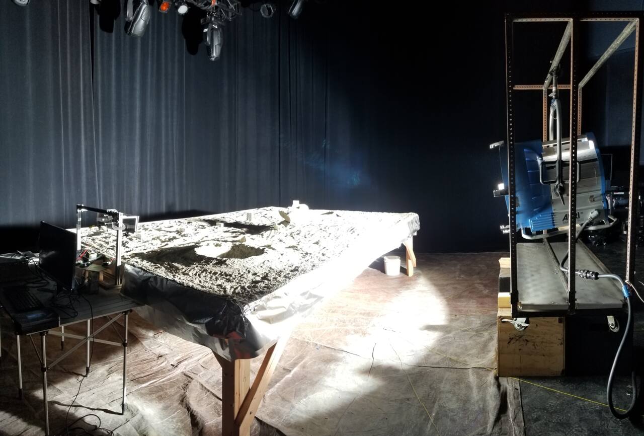
| Illumination | ARRI Arrimax 18/12 HMI head, 18 kW electrical, near grazing incidence |
| Simulant or terrain | Lunar-like material and color, with a line of rectangular blocks at surveyed locations |
| Instrumentation | Surveyed blocks as independent terrain geometry |
Source: [6].
A raised terrain table of lunar-like material with embedded rocks and craters, lit by a cinema HMI head positioned at bed height and set near grazing incidence because sun elevation at the lunar pole is a few degrees. Blackout curtains on the walls and floor prevent diffuse reflection back onto the terrain, so shadows stay close to black [6]. The stated target is the 1350 W/m2 and full infrared content reaching the lunar surface, against 1120 W/m2 at the Earth surface [6].
Outdoor terrain
Section titled “Outdoor terrain”| Parameter | Value |
|---|---|
| Working volume | Indoor sandbox, dimensions not published [8]. Outdoor slag terrain, extent not published [5] |
| Slope | Outdoor slag slopes of 20 to 25 degrees, a property of the site rather than a setting [5] |
| Simulant or terrain | Loose mixed grain size slag; a twist course of two sawtooth ramps; a railroad tie trench |
Full vehicle mobility work is done outdoors on slag slopes and craters, on a twist course of two sawtooth ramps set half a period out of phase so that the two sides of the suspension rock in opposition, and over a trench of two railroad ties [5]. Prototype driving for egress risk work is done in the indoor sandbox [8].
Instrumentation
Section titled “Instrumentation”Force measurement in the single wheel rig is by a six axis ATI Delta force and torque sensor, which resolves net thrust in the travel direction as well as actuator torques [3]. Sinkage comes from an encoder on the free vertical axis rather than from the drive train, so it is independent of wheel slip. The imaging chain uses a digital SLR with a 50 mm macro lens at 8 frames per second, sufficient for travel speeds of order 1.5 inches per second, framing a 12 inch wide by 8 inch deep patch of soil for wheels of 23 cm diameter [4]. Processing clusters each image into soil and non-soil regions, computes flow magnitude per pixel within the soil, and uses adaptive clustering to separate moving soil from static soil, giving the shear interface, the flow direction field, and the boundary between forward and rear flow [4].
Structural characterization uses roving hammer modal testing, with accelerometers reading frequency and magnitude while the article is tapped, in the mounting configuration it will fly in [9].
What it does not reproduce
Section titled “What it does not reproduce”Gravity is the largest omission. Scarab drawbar pull was measured at full weight, giving 2,000 N in mixed grain sized sand, approximately 0.7 times vehicle weight, and 2,700 N on concrete pavement, approximately equal to vehicle weight, with the authors recording that similar tests under a lunar gravity offload system remained to be run [5]. The same document notes that the loads induced during 1 m coring in simulant were relatively moderate and that a gravity offload system would be needed to make the drilling loading conditions flight-like [5].
The shear imaging technique substitutes a symmetry-plane boundary condition for the real mid-width condition of a full wheel. The authors state the requirement explicitly: the zero shear stress plane of symmetry is equivalent to a half-width wheel against the glass only if the soil particle to glass interface is sufficiently low friction, ideally zero [3]. Nothing in the published description measures the residual wall friction.
The vacuum specification is a thermal criterion. The stated reason for 5 x 10^-4 torr is that it reduces convective heat transfer to a negligible level, being about 1.5 million times less air than at atmospheric pressure [1]. Nothing in the description addresses outgassing of a dusty article, dust adhesion in vacuum, or holding pressure with regolith in the chamber.
Illumination fidelity is bounded by what a cinema lamp can do. The operators describe lunar light as more intense, less diffuse and lower in the sky than terrestrial sunlight, and note that the Earth atmosphere both reduces the constant from 1350 W/m2 to 1120 W/m2 and scatters the beam so that shadows are neither sharp-edged nor truly black [6]. The consequence they identify for camera design is that lunar terrain in mixed lighting is nearly binary: sunlit regions saturate at exposures long enough to see into shadow, and shadowed regions lit only by the rover at about 1 W/m2 read as almost entirely black [7].
Campaigns run there
Section titled “Campaigns run there”Scarab mobility characterization, 2007. Laboratory drawbar pull tests established 2,000 N in mixed grain sized sand and 2,700 N on concrete for the rubber skid loader tires, and outdoor testing on 20 to 25 degree slag slopes measured the effect of body leaning on cross-slope traction: holding a straight path over 11 m, slip was 15 percent downhill without leaning and 7 percent with the body leaned into the slope, attributed to weight transfer onto the uphill wheels and to the wheels cutting terraces rather than skiing across the slope face [5]. Rock obstacles of 40 to 50 cm were climbed, a 50 cm trench between two railroad ties was bridged, and a single continuous 1 km traverse was run, chosen to represent the distance between drill sites. NORCAT’s coring drill breadboard was integrated on the vehicle and drilled to its full 1 m depth in lunar soil simulant [5]. See scarab.
Grouser geometry study, 2011 to 2012. The single wheel imaging rig was used to photograph the shear interface below rigid wheels with varying grouser height and spacing in GRC-1, at 20 percent slip for all combinations and over full slip curves for a subset [3][4]. The result was a design relation between grouser spacing and the extent of the shear zone, obtained from optical flow on the imaged grains rather than inferred from drawbar pull alone [3][4].
Push-pull locomotion, 2012. Carnegie Mellon contributed the soil imaging rig, filled with GRC-1 prepared by loosening, levelling and compacting, to a joint study with NASA Glenn on inching locomotion; the vehicle-scale drawbar pull comparisons in the same study were run in the Glenn SLOPE soil bin of approximately 8 m by 3 m by 0.3 m, also filled with GRC-1 [10]. The division of labor is the pattern the CMU rigs follow: sub-surface soil mechanics at Carnegie Mellon, vehicle-scale traction at a larger NASA bin.
MoonRanger thermal vacuum campaign, 2021. Components and assemblies were tested to verify the conductance of thermal interfaces, with the stated purpose of letting tested performance take precedence over prior analysis and simulation, and of catching interface problems before full system test [2]. The wheel module was run in the chamber with its rim on the cold plate and subsequently passed launch vibration testing [2]. See moonranger.
MoonRanger perception and lighting tests, 2021. The terrain bed with surveyed blocks was used to check that the terrain geometry the rover reconstructs matches the scene, under 18 kW HMI illumination at near-grazing incidence with blackout curtains [6]. A parallel exposure study established that images taken while the camera swept through a turn at 50 ms exposure were blurred beyond use for stereo, while the same exposure from a stationary camera was sharp, which bore directly on whether the rover could image while in continuous motion rather than stopping for every frame [7].
MoonRanger egress risk tests. Prototype driving in the CMU sandbox, combined with Monte Carlo rock distribution modeling, set the rock protrusion height thresholds used to classify drop-deploy egress risk: success at 6 cm, negotiable at 8 cm, high risk above 10 cm despite single 10 cm rocks having been driven over, and high risk of belly contact and internal damage at 14 cm [8].
MoonRanger modal survey. Roving hammer tests on the inverted chassis, bolted in its lander attachment configuration, returned response frequencies of 107, 119 and 170 Hz against a requirement that the lowest frequency exceed 100 Hz [9]. Mode shapes agreed with Ansys predictions while the frequencies differed from earlier vibration test results. A wheel module tapped separately gave a first mode of 127 Hz for the older module against 135 Hz from vibration testing, and 142 Hz for the 60 mm wide wheel module [9].
CubeRover. Carnegie Mellon co-developed the initial CubeRover prototypes, and mobility verification moved to NASA KSC Granular Mechanics and Regolith Operations laboratory. That campaign ran more than 150 mobility tests with 11 wheel sets, covering drawbar pull, slope and point turn performance, with some wheel sets climbing 30 degree slopes [11]. See cuberover and gmro-lab.
Scarab field characterization, 2009. A later campaign took Scarab from the Glenn SLOPE bin through Moses Lake sand dunes to a Mauna Kea analog site with the NORCAT drill and a volatiles payload [13]. Instrumented cross-slope tests on GRC-1 reduced downhill slip from 37 percent to 15 percent at 20 degrees with active body roll control, and drawbar pull across seven soils stayed in a band of 20 to 39 percent of vehicle weight [13].
MoonRanger thermal modeling. The MoonRanger thermal design used a hand resistance network, a finite element model and a finite difference model [22], and set a surface operating band of -10 to 35 C [22] and a multilayer insulation emissivity window of 0.007 to 0.02 [22]. The paper contains no thermal vacuum data, so the chamber campaign above is the only test counterpart to those predictions [22].
What is not established
Section titled “What is not established”No published CMU description gives the wheel-rig bin length, the perception bed dimensions, the sandbox area or any access terms. No gravity offload is used, so traction, sinkage and slip from Scarab and the single wheel rig are Earth-gravity results, and the Scarab authors state that extrapolation to the Moon needs further testing [5][13]. GRC-1 reproduces frictional but not cohesive lunar strength [14]. Polar regolith is the stated target of MoonRanger and Scarab, but the Apollo-based soil database has no polar measurements [31]; the evidence that polar soil differs is from lab thermal cycling and vibration compaction on JSC-1A, with only a small density change in the thermal cycling work [28][29], and polar cold trap temperatures are known from orbit, as low as 29 K in shadowed floors [34]. None of the rigs combines vacuum, cold and regolith in one chamber, and residual wall friction in the glass-wall rig is not measured [1][3]. The egress risk bands come from simulation with terrain statistics inferred from other missions, without trial counts [8]. The CubeRover results are from a press release without drawbar values or wheel geometry [11].
References
Section titled “References”References
- (2022). MoonRanger project log: Vacuum Chamber. labs.ri.cmu.edu/moonranger/vacuum-chamber
BibTeX
@misc{moonrangerprojectlogvacuum, title = {MoonRanger project log: Vacuum Chamber}, organization = {labs.ri.cmu.edu}, year = {2022}, url = {https://labs.ri.cmu.edu/moonranger/vacuum-chamber/} } - (2022). MoonRanger project log: Thermal Vacuum Testing. labs.ri.cmu.edu/moonranger/thermal-vacuum-testing
BibTeX
@misc{moonrangerprojectlogthermal2, title = {MoonRanger project log: Thermal Vacuum Testing}, organization = {labs.ri.cmu.edu}, year = {2022}, url = {https://labs.ri.cmu.edu/moonranger/thermal-vacuum-testing/} } - Moreland, S., Skonieczny, K., Inotsume, H. and Wettergreen, D. (2012). Soil Behavior of Wheels with Grousers for Planetary Rovers
. IEEE Aerospace Conference. Source
BibTeX
@inproceedings{moreland2012soil, title = {Soil Behavior of Wheels with Grousers for Planetary Rovers}, author = {Moreland, Scott and Skonieczny, Krzysztof and Inotsume, Hiroaki and Wettergreen, David}, booktitle = {IEEE Aerospace Conference}, pages = {1-8}, address = {Big Sky, Montana}, year = {2012}, doi = {10.1109/aero.2012.6187040}, abstract = {The performance of wheels operating in loose granular material for the application of planetary vehicles is well researched but little effort has been made to study the soil shearing which governs traction. Net traction measurements and application of energy metrics have been solely relied upon to investigate performance but lack the ability to evaluate or describe soil-wheel interaction leading to thrust and resistances. The complexity of rim and grouser interaction with the ground has also prevented adequate models from being formulated. This work relies on empirical data gathered in attempt to study the effects of rim surface on soil shearing and ultimately how this governs traction. A novel experimentation and analysis technique was developed to enable investigation of terramechanics fundamentals in great detail. This technique, the Shear Interface Imaging Analysis Tool, is utilized to provide visualization and analysis capability of soil motion at and below the wheel-soil interface. Analysis of the resulting displacement field identifies clusters of soil motion and shear interfaces. Complexities in soil flow patterns greatly affect soil structure below the wheel and the resulting tractive capability. Grouser parameter variations, spacing and height, are studied for a rigid wheel. The results of soil shear interface analysis for wheels with grousers are presented. The processes of thrust and resistances are investigated and behavior characterized for grousered wheels.} } - Moreland, S., Skonieczny, K., Wettergreen, D., Creager, C. and Asnani, V. (2011). Soil Motion Analysis System for Examining Wheel-Soil Shearing
. Conference of the International. Source
BibTeX
@inproceedings{moreland2011soil, title = {Soil Motion Analysis System for Examining Wheel-Soil Shearing}, author = {Moreland, Scott and Skonieczny, Krzysztof and Wettergreen, David and Creager, Colin and Asnani, Vivake}, booktitle = {Conference of the International}, address = {Blacksburg, Virginia}, year = {2011}, doi = {10.1184/r1/6560918.v1} } - Bartlett, P., Wettergreen, D. and Whittaker, W. L. (2008). Design of the Scarab Rover for Mobility and Drilling in the Lunar Cold Traps
. International Symposium on Artificial Intelligence, Robotics and Automation in Space. Source
BibTeX
@inproceedings{bartlett2008design, title = {Design of the Scarab Rover for Mobility and Drilling in the Lunar Cold Traps}, author = {Bartlett, Paul and Wettergreen, David and Whittaker, William L.}, booktitle = {International Symposium on Artificial Intelligence, Robotics and Automation in Space}, address = {Los Angeles, California}, year = {2008}, url = {https://www.ri.cmu.edu/pub_files/2008/2/08isairas.scarab.bartlett.pdf} } - (2021). MoonRanger project log: Perception Testbed and Lighting. labs.ri.cmu.edu/moonranger/perception-testbed-and-lighting
BibTeX
@misc{moonrangerprojectlogperception, title = {MoonRanger project log: Perception Testbed and Lighting}, organization = {labs.ri.cmu.edu}, year = {2021}, url = {https://labs.ri.cmu.edu/moonranger/perception-testbed-and-lighting/} } - (2022). MoonRanger project log: Binary Lighting and Motion Blur. labs.ri.cmu.edu/moonranger/binary-lighting-and-motion-blur
BibTeX
@misc{moonrangerprojectlogbinary, title = {MoonRanger project log: Binary Lighting and Motion Blur}, organization = {labs.ri.cmu.edu}, year = {2022}, url = {https://labs.ri.cmu.edu/moonranger/binary-lighting-and-motion-blur/} } - (2022). MoonRanger project log: Between a Moon Rock and a Hard Place. labs.ri.cmu.edu/moonranger/between-a-moon-rock-and-a-hard-place
BibTeX
@misc{moonrangerprojectlogbetween, title = {MoonRanger project log: Between a Moon Rock and a Hard Place}, organization = {labs.ri.cmu.edu}, year = {2022}, url = {https://labs.ri.cmu.edu/moonranger/between-a-moon-rock-and-a-hard-place/} } - (2021). MoonRanger project log: Roving Hammer Testing. labs.ri.cmu.edu/moonranger/roving-hammer-testing
BibTeX
@misc{moonrangerprojectlogroving, title = {MoonRanger project log: Roving Hammer Testing}, organization = {labs.ri.cmu.edu}, year = {2021}, url = {https://labs.ri.cmu.edu/moonranger/roving-hammer-testing/} } - Creager, C., Moreland, S., Skonieczny, K., Johnson, K., Asnani, V. and Gilligan, R. (2012). Benefit of Push-pull Locomotion for Planetary Rover Mobility
. ASCE Earth and Space Conference. Source
BibTeX
@inproceedings{creager2012benefit, title = {Benefit of Push-pull Locomotion for Planetary Rover Mobility}, author = {Creager, Colin and Moreland, Scott and Skonieczny, Krzysztof and Johnson, Kyle and Asnani, Vivake and Gilligan, Ryan}, booktitle = {ASCE Earth and Space Conference}, pages = {11-20}, publisher = {American Society of Civil Engineers}, year = {2012}, doi = {10.1061/9780784412190.002}, abstract = {As NASA's exploration missions on planetary terrains become more aggressive, a focus on alternative modes of locomotion for rovers is necessary. In addition to climbing steep slopes, the terrain in these extreme environments is often unknown and can be extremely hard to traverse, increasing the likelihood of a vehicle or robot becoming damaged or immobilized. The conventional driving mode in which all wheels are either driven or free-rolling is very efficient on flat hard ground, but does not always provide enough traction to propel the vehicle through soft or steep terrain. This paper presents an alternative mode of travel and investigates the fundamental differences between these locomotion modes. The methods of "push-pull" locomotion discussed can be used with articulated wheeled vehicles and are identified as "walking" or "inching/inch-worming". In both cases, the braked non-rolling wheels provide increased thrust. An in-depth study of how soil reacts under a rolling wheel vs. a braked wheel was performed by visually observing the motion of particles beneath the surface. This novel technique consists of driving or dragging a wheel in a soil bin against a transparent wall while high resolution, high-rate photographs are taken. Optical flow software was then used to determine shearing patterns in the soil. Different failure modes were observed for the rolling and braked wheel cases. A quantitative comparison of inching vs. conventional driving was also performed on a full-scale vehicle through a series of drawbar pull tests in the Lunar terrain strength simulant, GRC-1. The effect of tire stiffness was also compared; typically compliant tires provide better traction when driving in soft soil, however it's been observed that rigid wheels may provide better thrust when non-rolling. Initial tests indicate up to a possible 40% increase in pull force capability at high slip when inching vs. rolling.} } - (2020). Astrobotic: CubeRover Completes Successful Mobility Testing. astrobotic.com/astrobotics-cuberover-completes-successful-mobility-te...
BibTeX
@misc{astroboticcuberover2, title = {Astrobotic: CubeRover Completes Successful Mobility Testing}, organization = {astrobotic.com}, year = {2020}, url = {https://www.astrobotic.com/astrobotics-cuberover-completes-successful-mobility-testing/} } - (2021). Carnegie Mellon Robotics Institute: MoonRanger. labs.ri.cmu.edu/moonranger
BibTeX
@misc{carnegiemellonroboticsinstitutemoonranger, title = {Carnegie Mellon Robotics Institute: MoonRanger}, organization = {labs.ri.cmu.edu}, year = {2021}, url = {https://labs.ri.cmu.edu/moonranger/} } - Wettergreen, D., Moreland, S., Skonieczny, K., Jonak, D., Kohanbash, D. and Teza, J. (2009). Design and Experimentation of a Rover Concept for Lunar Crater Resource Survey
. AIAA Aerospace Sciences Meeting including The New Horizons Forum and Aerospace Exposition. Source
BibTeX
@inproceedings{wettergreen2009design, title = {Design and Experimentation of a Rover Concept for Lunar Crater Resource Survey}, author = {Wettergreen, David and Moreland, Scott and Skonieczny, Krzysztof and Jonak, Dominic and Kohanbash, David and Teza, James}, booktitle = {AIAA Aerospace Sciences Meeting including The New Horizons Forum and Aerospace Exposition}, year = {2009}, doi = {10.2514/6.2009-1206}, abstract = {Scarab is a prospecting rover for lunar missions to survey resources, particularly water ice, in polar craters. It is designed for the deployment of a deep coring drill and for transport of soil analysis instruments. Its chassis can transform to stabilize the drill in contact with the ground and can also adjust to ascend and descent steep slopes of unconsolidated soil. Additional features include a compact body for better thermal regulation, laser scanners for dark navigation, and power system designed for a persistent, low-capacity source. Scarab was prototyped at the Robotics Institute, has undergone mobility testing in soils laboratories and field sites leading up to an integrated system test including the RESOLVE drill and instrument suite at the PISCES lunar analogue site on Mauna Kea in Hawaii} } - Oravec, H., Zeng, X. and Asnani, V. (2010). Design and characterization of GRC-1: A soil for lunar terramechanics testing in Earth-ambient conditions
. Journal of Terramechanics, 6. Source
BibTeX
@article{oravec2010design, title = {Design and characterization of GRC-1: A soil for lunar terramechanics testing in Earth-ambient conditions}, author = {Oravec, H.A. and Zeng, X. and Asnani, V.M.}, journal = {Journal of Terramechanics}, volume = {47}, number = {6}, pages = {361--377}, publisher = {Elsevier BV}, year = {2010}, doi = {10.1016/j.jterra.2010.04.006} } - Nakashima, H., Fujii, H., Oida, A., Momozu, M., Kanamori, H., Aoki, S., Yokoyama, T., Shimizu, H., Miyasaka, J. and Ohdoi, K. (2010). Discrete Element Method Analysis of Single Wheel Performance for a Small Lunar Rover on Sloped Terrain
. Journal of Terramechanics, 5. Source
BibTeX
@article{nakashima2010discrete, title = {Discrete Element Method Analysis of Single Wheel Performance for a Small Lunar Rover on Sloped Terrain}, author = {Nakashima, H. and Fujii, H. and Oida, A. and Momozu, M. and Kanamori, H. and Aoki, S. and Yokoyama, T. and Shimizu, H. and Miyasaka, J. and Ohdoi, K.}, journal = {Journal of Terramechanics}, volume = {47}, number = {5}, pages = {307--321}, year = {2010}, doi = {10.1016/j.jterra.2010.04.001} } - Apfelbeck, M., Kuß, S., Wedler, A., Gibbesch, A., Rebele, B. and Schäfer, B. (2009). A Novel Terramechanics Testbed Setup for Planetary Rover Wheel-Soil Interaction
. European Regional Conference of the International Society for Terrain-Vehicle Systems. Source
BibTeX
@inproceedings{apfelbeck2009novel, title = {A Novel Terramechanics Testbed Setup for Planetary Rover Wheel-Soil Interaction}, author = {Apfelbeck, Maximilian and Kuß, Sebastian and Wedler, Armin and Gibbesch, Andreas and Rebele, Bernhard and Schäfer, Bernd}, booktitle = {European Regional Conference of the International Society for Terrain-Vehicle Systems}, address = {Bremen}, year = {2009}, url = {https://elib.dlr.de/62703/} } - Buse, F. (2019). Fully Automated Single Wheel Testing with the DLR Terramechanics Robotics Locomotion Lab (TROLL)
. Symposium on Advanced Space Technologies in Robotics and Automation. Source
BibTeX
@inproceedings{buse2019fully, title = {Fully Automated Single Wheel Testing with the {DLR} Terramechanics Robotics Locomotion Lab ({TROLL})}, author = {Buse, Fabian}, booktitle = {Symposium on Advanced Space Technologies in Robotics and Automation}, organization = {European Space Agency}, address = {Noordwijk, The Netherlands}, year = {2019}, url = {https://elib.dlr.de/128404/} } - Lichtenheldt, R., Burlet, J.-Y., Buse, F. and Rebele, B. (2017). Towards Automated Soil Preparation for Planetary Rovers: Methods for Reproducible Measurements in Regolith Simulants
. Symposium on Advanced Space Technologies in Robotics and Automation. Source
BibTeX
@inproceedings{lichtenheldt2017towards, title = {Towards Automated Soil Preparation for Planetary Rovers: Methods for Reproducible Measurements in Regolith Simulants}, author = {Lichtenheldt, Roy and Burlet, Jean-Yves and Buse, Fabian and Rebele, Bernhard}, booktitle = {Symposium on Advanced Space Technologies in Robotics and Automation}, organization = {European Space Agency}, address = {Leiden, The Netherlands}, year = {2017}, url = {https://elib.dlr.de/112794/} } - Bekdash, O. S., Valle, P. S., Kim, K. J., Jarvis, S. L., Dunn, J. T., Norcross, J. R. and Abercromby, A. F. J. (2020). Development and Evaluation of the Active Response Gravity Offload System as a Lunar and Martian EVA Simulation Environment
. International Conference on Environmental Systems, 20205003610. Source
BibTeX
@inproceedings{bekdash2020development, title = {Development and Evaluation of the Active Response Gravity Offload System as a Lunar and Martian EVA Simulation Environment}, author = {Bekdash, Omar S. and Valle, Paul S. and Kim, Kyoung Jae and Jarvis, Sarah L. and Dunn, Jocelyn T. and Norcross, Jason R. and Abercromby, Andrew F. J.}, booktitle = {International Conference on Environmental Systems}, number = {20205003610}, institution = {NASA}, year = {2020}, url = {https://ntrs.nasa.gov/citations/20205003610}, abstract = {In preparation for future exploration missions, NASA seeks the ability to simulate partial-gravity operations for use in ground-based research, crew training, and engineering design evaluations. The Active Response Gravity Offload System (ARGOS) at the Johnson Space Center (JSC) is designed to simulate reduced gravity environments, such as lunar, Martian, or microgravity, using a robotic system similar to an overhead bridge crane. ARGOS continuously offloads a portion of a suited human’s weight during all dynamic motions within the test facility, which can include basic functional movements such as walking, running, and jumping, as well as a wide range of planetary surface activities. This system will be used as part of a metabolic-rate task characterization study to determine the workload associated with partial-gravity extravehicular activity (EVA). Pilot testing was conducted using the MKIII prototype planetary space suit and two gimbal designs to determine the ability of the ARGOS test environment to simulate planetary EVA operations. This paper will describe the lessons learned from the feasibility testing, simulation-environment mockup design, and the results from the pilot tests and their influence into the final study design. Being able to effectively simulate partial-gravity environments and characterize the performance of crewmembers will have an impact on multiple domains including suit design, task design, thermal models, and life-support-system capacity verification plans, among others.} } - Valle, P. S. (2017). Reduced Gravity Testing of Robots (and Humans) Using the Active Response Gravity Offload System. ntrs.nasa.gov/citations/20170008856
BibTeX
@misc{valle2017reduced, title = {Reduced Gravity Testing of Robots (and Humans) Using the Active Response Gravity Offload System}, author = {Valle, Paul Steinar}, howpublished = {Presentation at the Institute of Electrical and Electronics Engineers}, year = {2017}, url = {https://ntrs.nasa.gov/citations/20170008856}, abstract = {No abstract available} } - Wavrunek, T. A. (2021). Active Gravity Offloading System with Infrared Tracking for Rover Testing
. Michigan Technological University. Source
BibTeX
@mastersthesis{wavrunek2021active, title = {Active Gravity Offloading System with Infrared Tracking for Rover Testing}, author = {Wavrunek, Travis A.}, publisher = {Michigan Technological University}, school = {Michigan Technological University}, type = {Master of Science report, Mechanical Engineering}, year = {2021}, doi = {10.37099/mtu.dc.etdr/1213}, abstract = {Gravity offloading is a tool used to test how different gravitational forces will impact the mobility of rovers bound for Lunar or Martian expeditions. Previous approaches have been successful in simulating partial gravity environments, and this report details how the Infrared- Gravity offload (IRGO) system, developed for the Planetary Surface Technology Development Laboratory (PSTDL) and lunar simulant sandbox, has a similar aim. Through a series of iterations, IRGO has been developed to actively track an infrared beacon and follow a rover within the test chamber to eliminate inertial and friction forces along two horizonal axes. A portion of a rover’s weight is offloaded using a passive counterweight system to provide a third translational degree of freedom. Future plans to incorporate a lightweight gimbal as well as an active vertical axis are also discussed as solutions to improving the IRGO system.} } - Fisch, P. R. M., Bitanga, J. M. and Whittaker, W. L. (2020). Thermal Modeling and Design of a Micro-Rover for Lunar Polar Exploration
. International Symposium on Artificial Intelligence, Robotics and Automation in Space. Source
BibTeX
@inproceedings{fisch2020thermal, title = {Thermal Modeling and Design of a Micro-Rover for Lunar Polar Exploration}, author = {Fisch, Paulo R. M. and Bitanga, Jasmine M. and Whittaker, William L.}, booktitle = {International Symposium on Artificial Intelligence, Robotics and Automation in Space}, year = {2020}, url = {https://www.hou.usra.edu/meetings/isairas2020fullpapers/pdf/5058.pdf} } - Gerdts, S., Breckenridge, J. and Johnson, K. (2022). Lunar Rover Optimization Platform for Wheel Traction Studies
. NASA Glenn Research Center, 20200003006. Source
BibTeX
@techreport{gerdts2022lunar, title = {Lunar Rover Optimization Platform for Wheel Traction Studies}, author = {Gerdts, Stephen and Breckenridge, John and Johnson, Kyle}, number = {20200003006}, institution = {NASA Glenn Research Center}, year = {2022}, doi = {10.26226/m.632b0aa4f30377bc3bafa246}, abstract = {Robotic mobility systems expand the reach of future scientific and exploration missions to celestial bodies. Understanding the traction performance of these systems is necessary knowledge that informs mission-level requirements, such as power budgets and navigation envelopes. This paper covers the design, development, and verification of the four wheeled Lunar Rover Optimization Platform (LROP). This mass optimized platform is targeted to emulate future medium class rovers weighing up to 90 kg. The LROP has the ability to conduct various wheel design experiments such as obstacle traversal, slope ascent, and drawbar pull over a wheel loading range of 4.5 to 22.7 kg. The platform also has the ability to shift its center of gravity (CG) laterally and longitudinally to explore the CG shift effects on mobility performance. This knowledge is valuable for future rover designers exploring different payload packaging solutions. In this paper results from obstacle traversal test with varying angle of attack (AOA) and longitudinal CG position are reported along with results from slope ascent testing which proved-out the LROPs capabilities.} } - Li, Z. Q. and Bingham, L. K. (2022). NASA White Paper: Terramechanics for LTV Modeling and Simulation
. NASA, 20220010732. Source
BibTeX
@techreport{li2022nasa, title = {NASA White Paper: Terramechanics for LTV Modeling and Simulation}, author = {Li, Zu Qun and Bingham, Lee K.}, number = {20220010732}, institution = {NASA}, year = {2022}, url = {https://ntrs.nasa.gov/citations/20220010732}, abstract = {Simulating the interaction between wheel and soil is critical to the overall rover dynamics. This paper presented simple models for wheel soil interaction including the rolling resistances on the wheel due to soil compression and bull- dozing and the maximum tractive force between wheel and soil. Summary of typical lunar soil properties were presented in this paper and the wheel resis- tance model implementation and integration were also discussed. Integrating the wheel resistance model with the rover simulation will improve its dynamics and wheel slip models and enable the capability simulate the situation where wheel got stuck in the soil.} } - Knuth, M., Johnson, J. B., Hopkins, M., Sullivan, R. J. and Moore, J. (2012). Discrete element modeling of a Mars Exploration Rover wheel in granular material
. Journal of Terramechanics, 1. Source
BibTeX
@article{knuth2012discrete, title = {Discrete element modeling of a Mars Exploration Rover wheel in granular material}, author = {Knuth, M.A. and Johnson, Jerome B. and Hopkins, M.A. and Sullivan, Robert J. and Moore, J.M.}, journal = {Journal of Terramechanics}, volume = {49}, number = {1}, pages = {27-36}, publisher = {Elsevier BV}, year = {2012}, doi = {10.1016/j.jterra.2011.09.003} } - Sibille, L., Carpenter, P., Schlagheck, R. and French, R. A. (2006). Lunar Regolith Simulant Materials: Recommendations for Standardization, Production, and Usage
. NASA Marshall Space Flight Center, NASA/TP-2006-214605. Source
BibTeX
@techreport{sibille2006development, title = {Lunar Regolith Simulant Materials: Recommendations for Standardization, Production, and Usage}, author = {Sibille, Laurent and Carpenter, Paul and Schlagheck, R. and French, R. A.}, number = {NASA/TP-2006-214605}, institution = {NASA Marshall Space Flight Center}, type = {NASA Technical Publication}, year = {2006}, url = {https://ntrs.nasa.gov/citations/20060051776}, abstract = {Experience gained during the Apollo program demonstrated the need for extensive testing of surface systems in relevant environments, including regolith materials similar to those encountered on the lunar surface. As NASA embarks on a return to the Moon, it is clear that the current lunar sample inventory is not only insufficient to support lunar surface technology and system development, but its scientific value is too great to be consumed by destructive studies. Every effort must be made to utilize standard simulant materials, which will allow developers to reduce the cost, development, and operational risks to surface systems. The Lunar Regolith Simulant Materials Workshop held in Huntsville, AL, on January 24 26, 2005, identified the need for widely accepted standard reference lunar simulant materials to perform research and development of technologies required for lunar operations. The workshop also established a need for a common, traceable, and repeatable process regarding the standardization, characterization, and distribution of lunar simulants. This document presents recommendations for the standardization, production and usage of lunar regolith simulant materials.} } - Kleinhenz, J. E. and Wilkinson, R. A. (2014). Development and Testing of an ISRU Soil Mechanics Vacuum Test Facility
. NASA Glenn Research Center, NASA/TM-2014-218389. Source
BibTeX
@techreport{kleinhenz2014development, title = {Development and Testing of an ISRU Soil Mechanics Vacuum Test Facility}, author = {Kleinhenz, Julie E. and Wilkinson, R. Allen}, number = {NASA/TM-2014-218389}, institution = {NASA Glenn Research Center}, year = {2014}, url = {https://ntrs.nasa.gov/citations/20150000323}, abstract = {For extraterrestrial missions, earth based testing in relevant environments is key to successful hardware development. This is true for both early component level development and system level integration. For In-Situ Resource Utilization (ISRU) on the moon, hardware must interface with the surface material, or regolith, in a vacuum environment. A relevant test environment will therefore involve a vacuum chamber with a controlled, properly conditioned bed of lunar regolith simulant. However, in earth-based granular media, such as lunar regolith simulant, gases trapped within the material pore structures and water adsorbed to all particle surfaces will release when exposed to vacuum. Early vacuum testing has shown that this gas release can occur violently, which loosens and weakens the simulant, altering the consolidation state. A mid-size chamber (3.66 m tall, 1.5 m inner diameter) at the NASA Glenn Research Center has been modified to create a soil mechanics test facility. A 0.64 m deep by 0.914 m square metric ton bed of lunar simulant was placed under vacuum using a variety of pumping techniques. Both GRC-3 and LHT-3M simulant types were used. Data obtained from an electric cone penetrometer can be used to determine strength properties at vacuum including: cohesion, friction angle, bulk density and shear modulus. Simulant disruptions, caused by off-gassing, affected the strength properties, but could be mitigated by reducing pump rate. No disruptions were observed at pressures below 2.5 Torr, regardless of the pump rate. The slow off-gassing of the soil at low pressure lead to long test times; a full week to reach 10(exp -5) Torr. Robotic soil manipulation would enable multiple ISRU hardware test within the same vacuum cycle. The feasibility of a robotically controlled auger and tamper was explored at vacuum conditions.} } - Metzger, P. T., Anderson, S. and Colaprete, A. (2018). Experiments Indicate Regolith is Looser in the Lunar Polar Regions than at the Lunar Landing Sites
. ASCE Earth and Space Conference. Source
BibTeX
@inproceedings{metzger2018experiments, title = {Experiments Indicate Regolith is Looser in the Lunar Polar Regions than at the Lunar Landing Sites}, author = {Metzger, Philip T. and Anderson, Serena and Colaprete, Anthony}, booktitle = {ASCE Earth and Space Conference}, pages = {79-85}, publisher = {American Society of Civil Engineers}, year = {2018}, doi = {10.1061/9780784481899.009}, abstract = {Since the Apollo program or earlier it has been widely believed that the lunar regolith was compacted through vibrations including nearby impact events, thermal stress release in the regolith, deep moon quakes, and shallow moon quakes. Experiments have shown that vibrations both compact and re-loosen regolith as a function of depth in the lunar soil column and amplitude of the vibrational acceleration. Experiments have also identified another process that is extremely effective at compacting regolith: the expansion and contraction of individual regolith grains due to thermal cycling in the upper part of the regolith where the diurnal thermal wave exists. Remote sensing data sets from the Moon suggest that the soil is less compacted in regions where there is less thermal cycling, including infrared emissions measured by the Diviner radiometer on the Lunar Reconnaissance Orbiter (LRO). Here, we performed additional experiments in thermal cycling simulated lunar regolith and confirm that it is an effective compaction mechanism and may explain the remote sensing data. This creates a consistent picture that the soil really is looser in the upper layers in polar regions, which may be a challenge for rovers that must drive in the looser soil.} } - Gamsky, J. N. and Metzger, P. T. (2010). The Physical State of Lunar Soil in the Permanently Shadowed Craters of the Moon
. ASCE Earth and Space Conference. Source
BibTeX
@inproceedings{gamsky2010physical, title = {The Physical State of Lunar Soil in the Permanently Shadowed Craters of the Moon}, author = {Gamsky, Jacob N. and Metzger, Philip T.}, booktitle = {ASCE Earth and Space Conference}, pages = {260-265}, publisher = {American Society of Civil Engineers}, year = {2010}, doi = {10.1061/41096(366)27}, abstract = {The physical state of the lunar soil in the permanently shadowed craters of the moon is inferred from experimental investigation. The permanently shadowed craters do not undergo the same thermal cycling experienced by other parts of the moon and therefore could be slightly less compacted. This study is significant because excavating, roving, and landing interactions, along with the energy budgets and deployment schedules for associated technology, need to be scaled and designed properly. Results indicate that the degree of compaction due to thermal cycling is a function of the depth in the soil column.} } - Ludivig, P., Calzada-Diaz, A., Olivares Mendez, M. A., Voos, H. and Lamamy, J. (2020). Building a Piece of the Moon: Construction of Two Indoor Lunar Analogue Environments
. International Astronautical Congress, IAC-20-A3.2B.3. Source
BibTeX
@inproceedings{ludivig2020building, title = {Building a Piece of the {Moon}: Construction of Two Indoor Lunar Analogue Environments}, author = {Ludivig, Philippe and Calzada-Diaz, Abigail and Olivares Mendez, Miguel Angel and Voos, Holger and Lamamy, Julien}, booktitle = {International Astronautical Congress}, number = {IAC-20-A3.2B.3}, organization = {International Astronautical Federation}, year = {2020}, url = {https://orbilu.uni.lu/handle/10993/45539} } - Heiken, G. H., Vaniman, D. T. and French, B. M. (1991). Lunar Sourcebook: A User's Guide to the Moon
. Endeavour. Source
BibTeX
@book{heiken1991lunar, title = {Lunar Sourcebook: A User's Guide to the Moon}, author = {Heiken, Grant H. and Vaniman, David T. and French, Bevan M.}, journal = {Endeavour}, volume = {16}, pages = {96}, publisher = {Cambridge University Press}, year = {1991}, doi = {10.1016/0160-9327(92)90014-g} } - Gaier, J. R. and Sechkar, E. A. (2007). Lunar Simulation in the Lunar Dust Adhesion Bell Jar
. AIAA Aerospace Sciences Meeting, NASA/TM-2007-214704. Source
BibTeX
@inproceedings{gaier2007lunar, title = {Lunar Simulation in the Lunar Dust Adhesion Bell Jar}, author = {Gaier, James R. and Sechkar, Edward A.}, booktitle = {AIAA Aerospace Sciences Meeting}, number = {NASA/TM-2007-214704}, institution = {NASA}, year = {2007}, doi = {10.2514/6.2007-963}, abstract = {The Lunar Dust Adhesion Bell Jar has been assembled at the NASA Glenn Research Center to provide a high fidelity lunar simulation facility to test the interactions of lunar dust and lunar dust simulant with candidate aerospace materials and coatings. It has a sophisticated design which enables it to treat dust in a way that will remove adsorbed gases and create a chemically reactive surface. It can simulate the vacuum, thermal, and radiation environments of the Moon, including proximate areas of illuminated heat and extremely cold shadow. It is expected to be a valuable tool in the development of dust repellant and cleaning technologies for lunar surface systems.} } - Jarvis, S. L., Vu, L. Q., Gupta, G., Benson, E., Kim, K. H., Rhodes, R. and Rajulu, S. L. (2023). Development of ARGOS (Active Response Gravity Offload System) Offloading Assessments and Methodology for Lunar EVA Simulations
. International Conference on Environmental Systems, 20230002430. Source
BibTeX
@inproceedings{jarvis2023development, title = {Development of ARGOS (Active Response Gravity Offload System) Offloading Assessments and Methodology for Lunar EVA Simulations}, author = {Jarvis, Sarah L. and Vu, Linh Q. and Gupta, Garima and Benson, Elizabeth and Kim, K. Han and Rhodes, Richard and Rajulu, Sudhakar L.}, booktitle = {International Conference on Environmental Systems}, number = {20230002430}, institution = {NASA}, address = {Calgary}, year = {2023}, url = {https://ntrs.nasa.gov/citations/20230002430}, abstract = {The Active Response Gravity Offload System (ARGOS) at NASA Johnson Space Center (JSC) is an analog environment that can offload pressurized suited subjects for various reduced gravity simulations. The suit is suspended from a robotic overhead crane by a cable connected to the suit via a gimbal with an adjustable pivot point (i.e. offload attachment). There has been increased interest in providing planetary pressurized suited training at ARGOS in preparation for lunar missions. Determination of the appropriate gimbal pivot point location for a given subject is vital for a high-fidelity functional lunar simulation. Interactions between the pivot point location and human-spacesuit center of gravity (CG) can result in righting moments that may lead to artificially stable or unrealistically challenging configurations. Changing the pivot point location is time consuming and repeated adjustment can result in loss of valuable pressurized suited time. This paper aims to share knowledge obtained from the offloading characterization efforts during pressurized suited testing at ARGOS and document the ongoing process to define an appropriate pivot point location through iterative quantitative and qualitative assessments. Human-spacesuit CG locations for the ARGOS lunar simulation were estimated using a 3D body scan and density model combined with spacesuit hardware CAD and specifications. Early pilot testing of the gimbal revealed that setting the pivot point coincident with the modeled CG location was not always possible due to the current gimbal design, and small pivot point shifts had noticeable effects on subject stability. Fourteen subjects performed a series of CG-related tasks in the Exploration Extravehicular Mobility Unit (xEMU) to assess simulation characteristics. Through iterative testing, this task list evolved to streamline the process needed to efficiently identify a suitable pivot point for a given subject. The developed methodology will be critical for pivot point selection during astronaut training in the ARGOS environment.} } - Paige, D. A., Siegler, M. A., Zhang, J. A., Hayne, P. O., Foote, E. J., Bennett, K. A., Vasavada, A. R., Greenhagen, B. T., Schofield, J. T., McCleese, D. J., Foote, M. C., DeJong, E., Bills, B. G., Hartford, W., Murray, B. C., Allen, C. C., Snook, K., Soderblom, L. A., Calcutt, S., Taylor, F. W., Bowles, N. E., Bandfield, J. L., Elphic, R., Ghent, R., Glotch, T. D., Wyatt, M. B. and Lucey, P. G. (2010). Diviner Lunar Radiometer Observations of Cold Traps in the Moon's South Polar Region
. Science, 6003. Source
BibTeX
@article{paige2010diviner,
  title = {{Diviner} Lunar Radiometer Observations of Cold Traps in the {Moon}'s South Polar Region},
  author = {Paige, David A. and Siegler, Matthew A. and Zhang, Jo Ann and Hayne, Paul O. and Foote, Emily J. and Bennett, Kristen A. and Vasavada, Ashwin R. and Greenhagen, Benjamin T. and Schofield, John T. and McCleese, Daniel J. and Foote, Marc C. and DeJong, Eric and Bills, Bruce G. and Hartford, Wayne and Murray, Bruce C. and Allen, Carlton C. and Snook, Kelly and Soderblom, Laurence A. and Calcutt, Simon and Taylor, Fredric W. and Bowles, Neil E. and Bandfield, Joshua L. and Elphic, Richard and Ghent, Rebecca and Glotch, Timothy D. and Wyatt, Michael B. and Lucey, Paul G.},
  journal = {Science},
  volume = {330},
  number = {6003},
  pages = {479--482},
  year = {2010},
  doi = {10.1126/science.1187726},
  abstract = {Watering the Moon About a year ago, a spent upper stage of an Atlas rocket was deliberately crashed into a crater at the south pole of the Moon, ejecting a plume of debris, dust, and vapor. The goal of this event, the Lunar Crater Observation and Sensing Satellite (LCROSS) experiment, was to search for water and other volatiles in the soil of one of the coldest places on the Moon: the permanently shadowed region within the Cabeus crater. Using ultraviolet, visible, and near-infrared spectroscopy data from accompanying craft, Colaprete et al. (p. 463 ; see the news story by Kerr ; see the cover) found evidence for the presence of water and other volatiles within the ejecta cloud. Schultz et al. (p. 468 ) monitored the different stages of the impact and the resulting plume. Gladstone et al. (p. 472 ), using an ultraviolet spectrograph onboard the Lunar Reconnaissance Orbiter (LRO), detected H 2 , CO, Ca, Hg, and Mg in the impact plume, and Hayne et al. (p. 477 ) measured the thermal signature of the impact and discovered that it had heated a 30 to 200 square-meter region from ∼40 kelvin to at least 950 kelvin. Paige et al. (p. 479) mapped cryogenic zones predictive of volatile entrapment, and Mitrofanov et al. (p. 483 ) used LRO instruments to confirm that surface temperatures in the south polar region persist even in sunlight. In all, about 155 kilograms of water vapor was emitted during the impact; meanwhile, the LRO continues to orbit the Moon, sending back a stream of data to help us understand the evolution of its complex surface structures.}
}