Canadarm (SRMS)
Program pages CSA: Canadarm
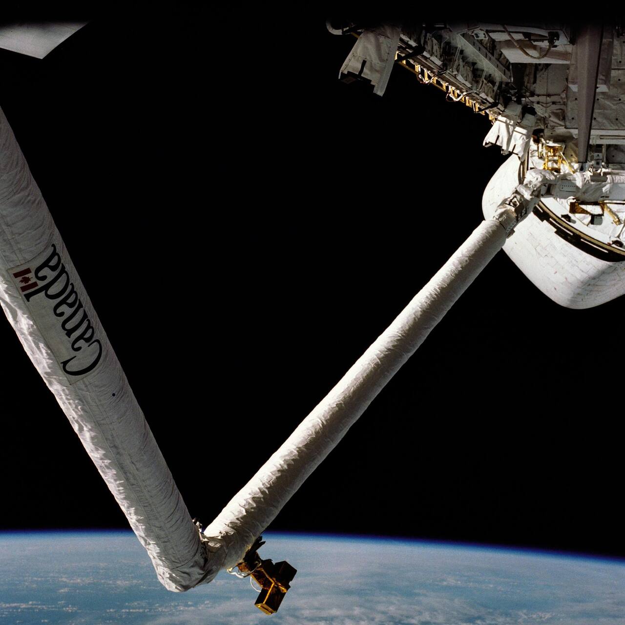 NASA. Public domain (NASA / US government work).
Overview
Section titled “Overview”The Shuttle Remote Manipulator System was the robotic arm of the Space Shuttle Orbiter, built in Canada and delivered to NASA as the Canadian contribution to the Shuttle program. It was specified to deploy satellites from the payload bay and to retrieve them, and its whole design follows from that requirement plus the constraint that it had to be carried in the payload bay envelope and could never be tested at full scale in one gravity [1].
It is the direct design ancestor of Canadarm2, and the comparison between the two is the clearest available account of what a station arm needs that a Shuttle arm did not [3].
Specifications
Section titled “Specifications”| Parameter | Value | Source |
|---|---|---|
| Length | 15.24 m | [3] |
| Effective reach from the base | about 10.7 m | [3] |
| Mass | 410 kg | [11] |
| Degrees of freedom | 6, no kinematic redundancy | [3] |
| Boom lengths | 6.38 m and 7.06 m | [6] |
| Boom exterior diameter | about 0.33 m, graphite epoxy | [6] |
| Rated payload | 29,484 kg in an 18.24 by 4.56 m envelope | [5] |
| Tip positioning accuracy | 51 mm (2 in) and 1 degree | [3] |
| Tip force limit | 44 N normal to the end effector, 25.4 mm deflection fully extended | [5] |
| Unloaded tip speed | 0.60 m/s | [11] |
| Loaded tip speed | 0.06 m/s | [11] |
| Gear ratio | about 738:1 at the wrist drives, 1842:1 at the shoulder | [7] |
| End effector diameter and length | 0.34 m by 0.46 m | [2] |
| End effector mass | 29.5 kg | [2] |
| Capture envelope | about 0.1 m lateral and axial, 15 degrees roll | [2] |
| Capture time | under 3 s | [2] |
| Rigidize time | under 20 s | [2] |
| Rigidized interface capacity | 474.5 N m bending, 949 N m roll | [2] |
| Maximum capture closing velocity | 0.061 m/s | [5] |
| Payload arrest distance | within 608 mm | [5] |
| Force-moment sensing | none | [1] |
| Design life | 100 mission cycles over 10 years, MTBF 8,333 h | [2] |
Mission profile
Section titled “Mission profile”| Parameter | Value | Source |
|---|---|---|
| Host | Space Shuttle Orbiter, bolted to the payload bay longeron | [3] |
| First flight | STS-2, November 1981 | |
| Missions flown | 91 | |
| Program end | July 2011 | |
| Roles beyond deployment and retrieval | satellite rescue and repair, mobile work platform for extravehicular crew, ISS assembly, Orbiter thermal protection system inspection after the loss of Columbia | |
| Operator station | Orbiter aft flight deck |
Rows with no marker are from [1].
Kinematics and workspace
Section titled “Kinematics and workspace”The arm is approximately 15.24 m long with six in-line joints arranged anthropomorphically: shoulder yaw and shoulder pitch, elbow pitch, and wrist pitch, wrist yaw and wrist roll [3]. All joints except wrist roll have travel limits smaller than plus or minus 180 degrees, and the effective reach envelope is about 10.7 m from the base of the arm.
Six joints are the minimum for arbitrary position and orientation of the end effector, so the arm has no kinematic redundancy. Every end-effector pose is reached by essentially one joint solution, and the arm therefore has singular configurations it cannot control through. Three are documented: the shoulder singularity, with the wrist yaw joint directly over the shoulder yaw axis, where plus or minus Y translation commands cannot be executed; the planar pitch or elbow singularity, with the arm straight out, where commands along plus X in end-effector mode are unavailable; and wrist gimbal lock, with wrist yaw at plus or minus 90 degrees, where some roll commands are impossible [1]. The flight software works around the shoulder and wrist cases in automatic and manual modes. When the wrist yaw joint comes within about 0.9 m of being directly over the shoulder joint during a Y translation, the software reorients the arm to drive in a circle around the singularity and then resumes the translation [1]. The elbow case is handled as an ordinary joint travel limit.
The two booms are thin-walled circular graphite epoxy tubes about 0.33 m in diameter, 6.38 m and 7.06 m long, with internal stabilization rings that keep shell ovalization frequencies above 180 Hz and resist local buckling [6]. Stiffness, not strength, drove the structure: the arm had to place its tip within 51 mm and one degree while holding a large payload [3].
The shoulder end is bolted to the Orbiter longeron and the end effector is fitted to the far end only [3]. This is the structural reason the SRMS could not relocate itself. It has one base and one hand, and the base is a fixed structural attachment rather than a capture interface. Canadarm2 answered this by making the arm symmetric about the elbow, with an identical Latching End Effector at each end and seven offset joints of plus or minus 270 degrees travel, so either end can grapple a Power Data Grapple Fixture and become the base and the arm can walk end over end along the station [3].
Joint design and actuation
Section titled “Joint design and actuation”Each degree of freedom is a motor module driving a gearbox, with local electronics that interpret drive commands originating in the cabin [1]. The motors are brushless DC and identical in all six joints, chosen that way to minimize qualification effort, to avoid brush maintenance, and because small motors through a high-ratio gearbox weigh far less than direct-drive motors of the same output torque.
Each gearbox has two stages. The first is a high-speed stage whose reduction ratio varies from joint to joint to meet that joint’s torque requirement. The second is identical in all joints and is a planetary design chosen to maximize the number of load paths, which gives high stiffness and low backlash [1]. Published overall ratios are approximately 738:1 at the three wrist drives and 1842:1 at the shoulder [7]. Joint housings are fabricated aluminum with steel and titanium in the higher load-bearing components, and the gears are Carpenter Custom 455 steel.
Backdrivability was the governing requirement. External loads applied to the tip can generate forces and moments beyond the structural capability of the arm, and a joint that backdrives bleeds off that load instead of reacting it [1]. Meeting the backdrive requirement demanded high gearbox efficiency, which in turn demanded manufacturing tolerances tight enough that gears had to be picked by a select-on-manufacture program with a low yield. The same logic drove two further features: motor current limits in forward drive and in backdrive were matched to the measured gearbox efficiencies so that the joint could not apply excessive load in either direction, and the brakes had to permit backdriving while applied, so that a fault which set the brakes could not turn the arm into a rigid strut. Dynamic braking, decelerating a joint using the motor itself, was also built into the joint design.
End effector
Section titled “End effector”The end effector is 0.34 m in diameter, 0.46 m long, and masses 29.5 kg [2]. It grapples a payload fitted with a grapple fixture consisting of an 11 in grapple pin with a knob on the end [3], an optical target, and three alignment cams that mate to cam lobes on the end effector rim [3].
Capture is by snare rather than by jaws. Three cables are stored in grooves in a fixed ring and a rotating ring inside the open mouth of the effector. Rotating the inner ring through 80 degrees draws the three cables into a closing triangle around the grapple pin [2]. The mechanism is entirely insensitive to which way the pin is clocked and tolerates large misalignment, which is what a snare buys over a gripper: the capture envelope is about 0.1 m of lateral and axial misalignment and up to 15 degrees of roll, with a radial capture zone of 0.099 m to 0.123 m. Capture completes in under 3 seconds, which matters because the arm is closing on a payload with a relative velocity of up to 0.031 m/s and must tolerate impact at up to 0.122 m/s.
Rigidizing is a separate motion. Once the snares are closed the carriage carrying the snare rings is drawn about 25 mm back into the body of the effector on three ball screws of 0.0051 m lead, pulling the grapple pin knob against the cam lobes with roughly 3,560 N and seating the payload with no residual freedom [2]. Belleville springs set the preload between 2,670 N and 3,114 N so that the joint stays loaded across the thermal range, where the pin load varies between 3,290 N and 3,650 N. Rigidizing takes under 20 seconds. The rigidized interface transfers 474.5 N m of bending with no interface separation and 949 N m of roll moment [2].
A single brushless DC motor drives both functions, with clutches separating the capture and rigidize mechanisms and spur gearing setting output torque [2]. Release in the prime mode is limited to a residual moment of 9.5e-6 N m imparted to the payload, which matters when releasing a free flyer that must not be tumbled. A backup release driven by a negator spring motor of about 70.6 mN m through a dog-tooth clutch can open the snares from any carriage position, at the cost of a much larger 0.068 N m release moment [2]. If the end effector fails while grappled, the standard Flight Releasable Grapple Fixture can be released by a spacewalking crew member from the payload side.
Post-rigidization pointing accuracy is 0.15 degrees in roll and 0.4 degrees in pitch and yaw [2]. Interface stiffness is at least 7864 N m/deg in bending and 3389.5 N m/deg in torsion, and bending capacity rises to 1627 N m once the interface has separated by 3 degrees. The end effector draws 125 W of heater power in operation and 88 W in survival mode [2].
Design life was 100 mission cycles at five operations per mission over ten years, with a mean time between failures of 8,333 hours; brakes and clutches were life-limited to 50 missions [2].
The effector also carries a Special Purpose End Effector connector fed by sixteen power and data lines routed the length of the arm. Mated to an Electrical Flight Grapple Fixture, it passes power and data to the grappled payload, and it was intended as the growth path for powered special-purpose end effectors [1].
Force and moment sensing
Section titled “Force and moment sensing”The SRMS had no force or moment sensor. The operator inferred contact loads from the joint responses, camera views, and the compliance of the arm itself. Force moment accommodation, in which measured contact loads are fed back into the rate commands to make constrained-motion tasks such as berthing easier, is identified in the program’s own lessons-learned as a capability the SRMS lacked and future arms should have [1]. Wrist force-moment sensing was added on Canadarm2 [3].
Structurally the tip is compliant by design. Weight and envelope limits capped the arm at 44 N (10 lbf) applied at right angles to the end effector, at which load the fully extended arm deflects 25.4 mm [5]. That accuracy has to hold while handling payloads to 29,484 kg in an 18.24 m by 4.56 m envelope, inside a payload bay whose minimum clearance around a payload is 76.2 mm. Capture is legal only below 0.061 m/s of relative velocity, and payload arrest must complete within 608 mm [5].
The control system models the arm’s compliance rather than treating it as a structural residual. An admittance model of the arm retains 15 to 20 dynamic modes with a 1000 lb payload against 4 to 6 unloaded, and resolves end-effector orientation to 0.01 degrees [6]. The Orbiter digital autopilot updates at 25 Hz and the smallest RCS thruster pulse has a 40 ms rise time [8], so attitude control inputs and arm structural modes occupy overlapping frequency ranges and the two systems have to be analyzed together.
Power and energy
Section titled “Power and energy”The arm ran on the Orbiter 28 V bus [1]. Published figures exist for the end effector alone: 125 W maximum for operation and 88 W for its heaters [2]. The 28 V bus later proved a constraint. When the Orbiter Boom Sensor System was added after Columbia, the existing SPEE cabling could not carry the current its sensors needed at 28 V, and the workaround was to draw from a 120 V source in the Shuttle that had been installed for ISS use [1].
Thermal
Section titled “Thermal”The 34,000 eclipse cycles per 5.8 years measured on LDEF [10] set the cycling load for any externally mounted structure, and gearbox and bearing lubricant has to hold its film at 1e-4 to 1e-7 torr, where vapor pressure rather than viscosity governs the selection [9]. The arm is wrapped in thermal blankets and carries an active, thermostatically controlled, redundant heater system [1]. End effector limits are representative of the mechanical hardware: minus 25 C to plus 70 C operating, minus 36 C to plus 81 C survival, and minus 50 C to plus 81 C qualification. The motor module, which dissipates internally, is rated minus 10 C to plus 85 C operating and minus 36 C to plus 96 C survival [2]. Thermal excursion is also a structural concern at the grapple interface, and the Belleville preload range was sized so that rigidize pin load stays within 3,290 N to 3,650 N across the thermal limits.
Compute and avionics
Section titled “Compute and avionics”Control is split between cabin electronics and arm-based electronics. The cabin equipment comprises the displays and controls panel with its two hand controllers and the Manipulator Controller Interface Unit, which is the main arm processor and handles all data transfer between the arm, the panel, and the Shuttle general purpose computer [1].
The trajectory computation lives in the Shuttle GPC. Flight software uses the Jacobian relating joint rates to the rates of the selected point of resolution, which may be a point on the end effector or a point within the payload, and inverts it to obtain commanded joint rates. When the Jacobian determinant goes to zero there is no solution, which is what makes the singularities above operationally binding [1]. The redundant seventh joint that resolves this on later station arms was not available: wrist roll travels plus or minus 360 degrees but the remaining five joints travel less than plus or minus 180 degrees [3]. The GPC issues rate and current limit commands to the arm-based electronics, and each joint’s local electronics closes the servo loop [1].
Actuator sizing for a space manipulator trades motor and gearbox mass against the payload inertia that has to be controlled, and the options available in this class were reviewed across the same period [7]. The Servo Power Amplifiers in the arm-based electronics were redesigned during the program. Studies of the payloads the arm would have to handle during station assembly showed that controllability would not be satisfactory for those masses, and the amplifier redesign restored it.
Autonomy
Section titled “Autonomy”The SRMS was not autonomous. Every motion was commanded by a crew member, and the automatic modes are pre-planned trajectories rather than any form of onboard decision making.
Autonomy is present only in fault protection. Built-in test equipment runs throughout the system, and the flight software adds a consistency check for runaway detection. Runaway was the dominant hazard, because a joint receiving unlimited motor current could drive a payload into the Orbiter. The check defines an envelope around the commanded motor rate for each joint, built from an offset from zero commanded rate, a second offset from the commanded rate, and a decay applied when a command is removed or changed. Actual motor rate must stay inside that envelope, and an excursion is annunciated only if it persists for more than four consecutive computation cycles, to avoid false alarms from command transients. Envelope constants were tuned so that a runaway is stopped within about 0.6 m of travel [1]. Self-checks elsewhere in the electronics stop the arm and drive caution and warning displays that tell the operator what failed and what capability remains. No runaway ever occurred in flight.
Communications
Section titled “Communications”The arm has no radio link of its own. It is hardwired into the Orbiter avionics through the MCIU, and all telemetry reaches the ground through the Orbiter downlink. Video from the arm cameras goes to the aft flight deck monitors and to the same downlink.
Payload and instruments
Section titled “Payload and instruments”The SRMS carries no science instruments. Its sensing exists to serve the operator.
Three camera assemblies were flown. A color camera on a pan and tilt unit near the elbow gave general situational awareness. A fixed camera on the wrist looked straight down the grapple axis and was the primary cue for capture: the operator flew the arm until the grapple fixture target fell inside an overlay drawn on the CRT display, then triggered capture from a switch on the rotational hand controller. A third, the SRMS side-view camera, was added after Columbia on the inboard side of the wrist joint for awareness during thermal protection system inspection [1]. A light assembly is co-located with the wrist camera. The optical target on the grapple fixture and the alignment cams are what convert that camera view into a capture decision, since the snare tolerates 0.1 m and up to 15 degrees but not an arbitrary approach [2].
The Orbiter Boom Sensor System, added for return to flight, is the closest thing to an instrument payload. It is a 15 m boom carried on the starboard manipulator positioning mechanisms, fitted with cameras and laser sensors, that the SRMS grapples and uses as an extension to reach and image the Orbiter underside [1]. Every post-Columbia mission used the SRMS and OBSS together to survey all critical thermal protection system surfaces, and the combination was certified as a stable enough platform to hold a spacewalking crew member at the boom tip for tile repair [1].
Modes of operation
Section titled “Modes of operation”Five families of mode were available [1].
Automatic covered both pre-programmed sequences and operator-commanded auto sequences. The latter required the operator to enter a final position and orientation before motion began. Auto sequences were used mainly for surveys and long repositioning maneuvers.
Manual augmented was the mode used for grappling, berthing and unberthing, tracking and capturing free flyers, and coarse positioning. The operator commanded the position and orientation of the point of resolution in real time through the hand controllers, with the software resolving those commands into joint rates. Maximum joint rates were set before flight and depended on the payload being handled. A vernier submode reduces control authority to 10 percent for precision work [5].
Single joint drive gave the operator one joint at a time under computer support, used mostly for cradling the arm.
Direct drive and backup drive were hardwired reduced-capability modes that applied a fixed voltage to a joint drive amplifier, single joint only, for use when the computer-supported modes were lost.
In manual augmented mode the translational hand controller commanded end effector motion in planes parallel to the Orbiter translation planes and the rotational hand controller commanded angular rates about axes parallel to Orbiter roll, pitch and yaw, originating at the end effector reference point. Either set of axes could be transposed by software to the end effector or to the mass centroid of the payload, after which commanded motion was defined in that frame instead [4].
The end effector itself had an automatic and a manual mode. In the standard automatic mode the rigidize command followed snare closure without operator action; in manual mode the operator commanded snare close and rigidize separately [1].
Late in the program a Position Orientation Hold Submode was added to manual augmented mode. The SRMS is a rate command system, so before POHS the position and attitude of the point of resolution were computed for display only and any drift had to be corrected by the operator. POHS projects a reference trajectory from the commanded rate and adds correction commands proportional to the deviation from it. The effect on uncommanded motion was large: on STS-31, without POHS, uncommanded motion exceeded 0.6 m and nearly 10 degrees, while on STS-103 with POHS active it was under 25 mm and about half a degree [1]. POHS was later extended to the OBSS case, where the crew had almost no direct view of the boom under the Orbiter.
Ground operations
Section titled “Ground operations”The arm was operated from the aft flight deck of the Orbiter by a crew member at the RMS workstation, using overhead and aft window views plus TV monitors, the displays and controls panel, and the two hand controllers [1]. The workstation layout was constrained early: the translational hand controller had to fit a 6 by 4 by 4.5 inch envelope, be usable by fifth-percentile female through ninety-fifth-percentile male crew members at a common design eye point, and be a displacement device rather than a force stick, with rate-dependent viscous damping generated in the stick itself rather than downstream in electronics, so as to preserve tactile feedback. Full-scale force was capped at 10 lbf because the operator is weightless and has nothing to brace against [4].
Ground support was simulation-heavy, and unusually so, because the arm could not support its own weight in one gravity and so could never be exercised as a complete system on the ground [1]. Four facilities carried the load:
- An air-bearing flat floor rig that blew air through pads under the arm’s support feet to offload gravity, allowing genuine multi-joint operation in a single plane. The arm could be mounted pitch-coupled, driving the three pitch joints, or yaw-coupled, driving the two yaw joints, with wrist roll available in either. It verified arm controls, tip accuracy, tip force, straight-line controllability, current limit response, and behavior under end effector to grapple fixture misalignment [1].
- SIMFAC, a manned real-time simulator at the contractor built around a TI 980B computer, used to develop the control laws and the hand controllers against the full 29,484 kg payload case [5]. Hand controller configuration and the resulting operator workload were evaluated on it directly [4].
- The Shuttle Engineering Simulator at JSC, combining an SRMS model with an aft cockpit mockup in a dome display. It modeled the Orbiter digital autopilot alongside the arm, so that coordinated operations between the arm operator and the pilot could be rehearsed with the 25 Hz autopilot and the arm’s structural modes coupled through the Orbiter [8]. It was used for engineering evaluation of software and procedure changes, for crew training, and repeatedly during flights to test proposed fixes to on-orbit problems [1].
- The Shuttle Avionics Integration Laboratory, which ran a hardware-in-the-loop MCIU against a computer model of the rest of the arm.
A Math Model Working Group coordinated the several independent modeling efforts, and the program identifies that structured multi-group forum as a lesson in its own right [1]. Arm models were upgraded continuously and by 2004 the real-time model had the fidelity of the best non-real-time model of the 1980s.
Technologies developed
Section titled “Technologies developed”The snare end effector and the grapple fixture it mates to became the standard space robotic capture interface. Canadarm2, Dextre, the Japanese Experiment Module arm and the European Robotic Arm all use snare-type latching end effectors on standardized fixtures, and the ability to grapple with 0.1 m and 15 degrees of misalignment tolerance is what makes robotic capture of a free-flying vehicle practical at all [2], [3].
Backdrivable high-ratio joints with matched forward and backdrive current limits established the load-protection approach used on later station arms, where the payload can outmass the arm by orders of magnitude and structural overload is the dominant failure mode [1].
Resolved-rate control from two hand controllers, with the point of resolution and the command frame both selectable in software, is the interface every subsequent space manipulator has inherited [4].
Four limits of the design are documented. Six degrees of freedom without redundancy left singularities the software had to steer around [3]; no force-moment sensing made constrained motion difficult [1]; a bolted base meant the arm could not relocate itself; and 28 V cabling sized to the original requirement constrained later capability growth. Canadarm2 addressed the first three with a seventh joint, wrist force-moment sensors, and symmetric latching end effectors.
Successors and context
Section titled “Successors and context”The SRMS design was carried forward in two steps. For the Space Station arm, the mechanism specification kept the SRMS joint gearbox as its basis: the Canadarm2 joint uses a two-stage reducer of 1845:1, against 1842:1 at the SRMS shoulder, with software travel limits of plus or minus 270 degrees and a minimum servo torque of 1044 N m [12]. The Canadarm2 latching end effector adds a latch and umbilical stage to the snare and rigidize sequence, which raises the handled payload mass to 116,000 kg and lets the interface carry 1800 W average and three video channels [12]. Required tip speed on Canadarm2 also depends on payload mass: it falls from 0.37 m/s unloaded to 0.012 m/s at 116,000 kg, with stopping distance growing from 0.61 m to 1.09 m. The source labels all of these design targets from a preliminary specification, not qualification results.
The mobility problem the SRMS did not have, relocating the arm along a truss, was studied separately. A 1987 trade study rejected continuous rails because they must be mounted at every location the transporter serves, and a monorail saved no mass because the higher stress on one rail returned its mass to that of a dual rail [13]. The concept retained drew the transporter along the truss through 9 cm node guide pins. It is a concept study of the same period as the SRMS flight record, and it reports no built hardware [13].
CSA lists the three generations side by side: Canadarm at 15 m and 410 kg, Canadarm2 at 17 m and 1497 kg, and Canadarm3 at 8.5 m and an estimated 715 kg [11]. A 2022 survey of space manipulators repeats those figures and places the family among the European Robotic Arm (11.3 m, 7 degrees of freedom) and Dextre (3.35 m, 7 degrees of freedom) [14]. Canadarm3 has not flown. The manufacturer’s page for it describes a goal-driven autonomous arm for the lunar Gateway but gives no mass, reach or degrees of freedom [15]. NASA’s servicing survey classifies manipulators by an 8 m reach threshold, which puts the SRMS in the long-reach group, and records that after the loss of Columbia the arm was paired with the Orbiter Boom Sensor System for every inspection [16].
Later arms and the wider field
Section titled “Later arms and the wider field”The SRMS is one of several flown or planned station and servicing arms, and the sources held for them describe different things: design intent, ground qualification, and a small number of flight experiments.
Space Station arm and its control. The Canadian overview of the Mobile Servicing System gives the SSRMS joint sequence as roll, yaw, pitch, pitch, pitch, yaw, roll, with all seven joints identical at plus or minus 270 degrees [17]. The seventh joint exists to steer the elbow independently of the payload, which avoids station hardware and singularities. It states berthing accuracy of about 5 to 10 cm for large payloads, aided by photogrammetry from the Space Vision System, and 2 mm motion resolution for Dextre [17]. All of these are requirements written before the arm flew [17]. A closed form inverse kinematic analysis locks one joint at a time to form three six-degree-of-freedom subchains, each with at most eight configurations obtained from quadratic polynomials. It is pure kinematics with no joint limits, dynamics or flexibility [18]. The SRMS workstation lineage continued in a 1994 human factors study in which nine NASA astronauts and one CSA astronaut compared four control implementations for the SSRMS workstation. Dedicated hardware controls beat on-screen software controls for camera operation and for arm backup drive. The study measured the controls, not the arm [21].
Dextre. Dextre was verified by sorting its components into commonality, legacy and new items, with commonality items cleared by an environment comparison rather than requalification. The paper is a process description written while verification was under way and reports no test results [19]. Ground tests with three Shuttle arm astronauts on a single-arm testbed showed what force-moment accommodation, the capability the SRMS lacked, changes. Inserting a converter unit from worst-case misalignment without it took 5 to over 15 minutes at peak contact forces of 190 to 220 N. With it active the same task took 2.0 to 2.5 minutes at 16 to 19 N [20]. Those are ground-testbed results with gravity compensation, not flight data.
Japanese arm. The JEMRMS Main Arm structural eigenvalues span two orders of magnitude, from 0.32 and 0.34 Hz unloaded on orbit to 0.19 Hz with a 500 kg payload and 0.046 Hz with a 7000 kg payload [22]. This is a 1994 design-stage table, before the engineering model existed. Qualification testing on an air bearing floor decomposed Main Arm tip positioning error into joint backlash (under 20.9 mm), housing alignment (16.4 mm), assembly (16.3 mm), control (5.3 mm) and thermal effects (2.2 mm), for a total under 44.7 mm and 0.463 degrees [23]. Measured two-dimensional floor results were 22.9 mm in x, 54.0 mm in z and 0.71 degrees [23]. A ground prototype of a common six-degree-of-freedom force-reflecting hand controller for both JEMRMS arms used an orthogonal geometry so that one master could drive any slave by swapping a transformation matrix. Its authors state it was not designed for space use [24].
European Robotic Arm. ERA is 11.3 m long with a 9.2 m span, seven degrees of freedom, 630 kg and accuracy of plus or minus 40 mm open loop and plus or minus 5 mm closed loop, with an 8000 kg maximum moveable mass and 0.10 m/s maximum tip speed [25]. These are specification values, not qualification results [25]. The joint motor unit drives a 454:1 epicyclic stage, and its spring-applied vacuum brake with a plasma-sprayed chromium oxide surface was qualified on the ground to a 4380 hour, 10700 operation duty cycle and stops the joint inertia in under 3.5 s between minus 55 and plus 85 C [26]. ESA’s 2021 brochure on the launch explains that Canadarm2 and JEMRMS cannot serve the Russian segment because the base point and payload interfaces differ. It is outreach material and gives no measurement conditions [27].
Flown servicing and teleoperation experiments. ETS-VII flew three rendezvous and docking experiments between July 1998 and October 1999 [28]. Measured lateral position error was 7 mm against a 25 mm requirement, with a single value per flight and a fully cooperative target [28]. On 22 November 1999 the ETS-VII arm was teleoperated from the ground under direct bilateral force coupling with a 6 to 7 s round-trip delay, holding a 5 N target contact force. The authors do not claim this is practical at that delay, and the sample is one to three runs per condition [29]. Orbital Express and the canceled Hubble robotic servicing mission are summarized together with Shuttle Hubble servicing in a GN&C synthesis that reports no navigation error statistics [34]. The history of Shuttle rendezvous supplies the operational context for the SRMS satellite captures and is a narrative record, not a data source [33]. Eleven years of Robotic Refueling Mission operations on the ISS, which used Dextre, yielded qualitative lessons on camera visibility, status indication and confirmation of irreversible actions, with no success rates or contact forces [32]. The Phase 1 Robotic Refueling Mission payload that Dextre later worked was designed cold-biased, with a radiator, multilayer insulation and heaters fed from two ISS feeds totaling about 290 W at maximum voltage against 230 W available from the Shuttle during transport. That record is analysis only, with no thermal vacuum or on-orbit temperatures [45]. On the Japanese side, the Kibo arm installed five experiment payloads in July and September 2009 and berthed and removed exposed pallets in 2009 and 2011. Before installation the crew pointed the wrist vision system at a marker on each of the twelve Exposed Facility Units and had the images measured on the ground, and the position corrections from the design values reached 10 cm, larger than expected [37]. The report is two pages and gives no distribution, contact load or timing [37].
Surveys and control research. A survey by groups that built several of these systems organizes space capture into observation and planning, approach, impact and grasp, and post-capture stabilization, and reviews free-floating dynamics, contact modeling and the flown demonstrations. It quotes specifications of unlaunched Chinese station arms from unverified sources [30]. Another survey inventories the ground facilities used to test such arms and builds its specification table from vendor and agency sources [31]. NASA’s servicing state-of-play series splits manipulators at 8 m reach into long and short groups, and its editions share large amounts of text [36]. For arms mounted on flexible structures, Reaction Null-Space control laws that suppress base vibration while tracking an end-effector path have been demonstrated only on a planar two-link bench arm on a flexible double beam [35]. Two reviews of the area, from 2011 and 2014, cover free-floating dynamics, target motion estimation, capture and post-capture stabilization, and the ground verification schemes. The 2011 review compares air-bearing tables, neutral buoyancy, parabolic flight or drop capsules, suspension gravity compensation and hardware-in-the-loop simulation, and quotes figures such as 20 s at 0.02 g for parabolic flight without test conditions [39]. The 2014 review adds flexible-manipulator vibration suppression and is secondary, so its arm lengths and degrees of freedom are as reported in the original papers [38].
Capture of non-cooperative targets, ground results only. The SRMS captured cooperative payloads fitted with a grapple fixture, and the later work addresses targets that have none. A reduced-order coupled rigid and flexible-body model of a client satellite with one or two flexible appendages predicts whether grapple contact excites flexible modes. It models only the first two modes of one symmetric satellite, omits damping, and its steady-state deformed amplitude is off by 20 percent against the reference simulation [40]. An open-loop impedance law with a compliant wrist, aimed at a coefficient of restitution of zero on contact, was verified on an air-floating test bed that emulates two-dimensional microgravity with a 63.2 kg target [41]. An extended Kalman filter that estimates the pose, velocities and inertia ratios of a tumbling satellite from laser camera data, paired with a minimum-cost interception planner, was validated in one laboratory run with two manipulators and no statistics [42]. A hand-eye visual servo and impedance scheme for capturing a non-cooperative satellite was tested on a planar ground field-robot testbed with model-based gravity compensation, so out-of-plane and full six-degree-of-freedom dynamics are not reproduced [43]. An adaptive reactionless control law with online estimation of the target mass, center-of-mass offset and inertia tensor addresses the moment after capture of an unknown tumbling target. It assumes a rigid grasp at a single predefined point with instantaneous rigidization and is a simulation result [44]. None of these has flown.
What is not established
Section titled “What is not established”No force or moment data from flight exist in the held sources, because the arm carried no sensor, so contact loads during berthing are known only from the operators’ accounts and the design limits [1]. The end effector figures are requirements and design values rather than measured qualification margins, and the 8,333 h mean time between failures is a requirement, not a demonstrated value [2]. The gear ratios and the harmonic drive comparison come from a survey that cites its test results by reference number, with no test conditions [7]. The CSA specification pages carry no tolerances or test conditions for any figure, including the loaded and unloaded tip speeds [11].
Other Shuttle arm literature surfaces in search but has no curation record, so it is not used here; the cited set is the held and curated material on this arm and its direct successors.
References
- Jorgensen, G. and Bains, E. (2011). SRMS History, Evolution and Lessons Learned
. AIAA SPACE Conference, 20110015563. Source
BibTeX
@inproceedings{jorgensen2011srms, title = {SRMS History, Evolution and Lessons Learned}, author = {Jorgensen, Glenn and Bains, Elizabeth}, booktitle = {AIAA SPACE Conference}, number = {20110015563}, institution = {NASA}, year = {2011}, doi = {10.2514/6.2011-7277}, abstract = {Early in the development of the Space Shuttle, it became clear that NASA needed a method of deploying and retrieving payloads from the payload bay. The Shuttle Remote Manipulator System (SRMS) was developed to fill this need. The 50 foot long robotic arm is an anthropomorphic design consisting of three electromechanical joints, six degrees of freedom, and two boom segments. Its composite boom construction provided a light weight solution needed for space operations. Additionally, a method of capturing payloads with the arm was required and a unique End Effector was developed using an electromechanical snare mechanism. The SRMS is operated using a Displays and Controls Panel and hand controllers located within the aft crew compartment of the shuttle. Although the SRMS was originally conceived to deploy and retrieve payloads, its generic capabilities allowed it to perform many other functions not originally conceived of. Over the years it has been used for deploying and retrieving constrained and free flying payloads, maneuvering and supporting EVA astronauts, satellite repair, International Space Station construction, and as a viewing aid for on-orbit International Space Station operations. After the Columbia accident, a robotically compatible Orbiter Boom Sensor System (OBSS) was developed and used in conjunction with the SRMS to scan the Thermal Protection System (TPS) of the shuttle. These scans ensure there is not a breach of the TPS prior to shuttle re-entry. Ground operations and pre mission simulation, analysis and planning played a major role in the success of the SRMS program. A Systems Engineering Simulator (SES) was developed to provide a utility complimentary to open loop engineering simulations. This system provided a closed-loop real-time pilot-driven simulation giving visual feedback, display and control panel interaction, and integration with other vehicle systems, such as GN&C. It has been useful for many more applications than traditional training. Evolution of the simulations, guided by the Math Model Working Group, showed the utility of input from multiple modeling groups with a structured forum for discussion.There were many unique development challenges in the areas of hardware, software, certification, modeling and simulation. Over the years, upgrades and enhancements were implemented to increase the capability, performance and safety of the SRMS. The history and evolution of the SRMS program provided many lessons learned that can be used for future space robotic systems.} } - Daniell, R. G. and Sachdev, S. S. (1982). The Design and Development of an End Effector for the Shuttle Remote Manipulator System
. Aerospace Mechanisms Symposium, 19820015473. Source
BibTeX
@inproceedings{daniell1982design, title = {The Design and Development of an End Effector for the Shuttle Remote Manipulator System}, author = {Daniell, R. G. and Sachdev, S. S.}, booktitle = {Aerospace Mechanisms Symposium}, number = {19820015473}, institution = {NASA}, year = {1982}, url = {https://ntrs.nasa.gov/citations/19820015473}, abstract = {The design requirements, the design, and qualification and development test problems encountered on the Remote Manipulator End Effector are described. The constraints and interfaces with the arm, the Orbiter, and the payload are identified. The design solution to meet the requirements is a unique device that provides a soft-docking feature termed capture and a hard-docking feature termed rigidization.} } - Taylor, E. C. and Ross, M. (1989). A Comparison of the Shuttle Remote Manipulator System and the Space Station Freedom Mobile Servicing Center
. NASA, 19900020594. Source
BibTeX
@techreport{taylor1989comparison, title = {A Comparison of the Shuttle Remote Manipulator System and the Space Station Freedom Mobile Servicing Center}, author = {Taylor, Edith C. and Ross, Michael}, number = {19900020594}, institution = {NASA}, year = {1989}, url = {https://ntrs.nasa.gov/citations/19900020594}, abstract = {The Shuttle Remote Manipulator System is a mature system which has successfully completed 18 flights. Its primary functional design driver was the capability to deploy and retrieve payloads from the Orbiter cargo bay. The Space Station Freedom Mobile Servicing Center is still in the requirements definition and early design stage. Its primary function design drivers are the capabilities: to support Space Station construction and assembly tasks; to provide external transportation about the Space Station; to provide handling capabilities for the Orbiter, free flyers, and payloads; to support attached payload servicing in the extravehicular environment; and to perform scheduled and un-scheduled maintenance on the Space Station. The differences between the two systems in the area of geometric configuration, mobility, sensor capabilities, control stations, control algorithms, handling performance, end effector dexterity, and fault tolerance are discussed.} } - Lippay, A. L. (1977). Multi-Axis Hand Controller for the Shuttle Remote Manipulator System
. The Annual Conference on Manual Control, 19790009332. Source
BibTeX
@inproceedings{lippay1977multi, title = {Multi-Axis Hand Controller for the Shuttle Remote Manipulator System}, author = {Lippay, Andrew L.}, booktitle = {The Annual Conference on Manual Control}, number = {19790009332}, organization = {CAE Electronics, Montreal}, address = {Cambridge, Massachusetts}, year = {1977}, url = {https://ntrs.nasa.gov/citations/19790009332}, abstract = {The Shuttle Remote Manipulator System, has a articulated arm of 50 ft. length with six motor-driven joints. The basic purpose is to establish physical contact with various space hardware items and maneuver these to the desired position and attitude with respect to the Orbiter, nulling out relative velocities and stabilizing the free-body system by managing residual energies. The normal operating mode is resolved-motion end-point rate control by man-in-loop command. The translational freedoms are defined so that the End Effector (EEFTR) of the arm will move in planes parallel to the principal translational planes of the Orbiter, at a rate commanded by the displacement of the Translation Hand Controller in the corresponding freedom and direction. The rotational freedoms are rate-controlled by the Rotation Hand Controller about pivot axes parallel to Orbiter roll, pitch and yaw, originating at the EEFTR reference point.} } - Lippay, A. L., Whitehead, G. D. and Wagner-Bartak, C. G. (1978). Manned Simulations of the SRMS in SIMFAC
. The Annual Conference on Manual Control, 19790007440. Source
BibTeX
@inproceedings{lippay1978manned, title = {Manned Simulations of the SRMS in SIMFAC}, author = {Lippay, Andrew L. and Whitehead, G. D. and Wagner-Bartak, C. G.}, booktitle = {The Annual Conference on Manual Control}, number = {19790007440}, institution = {NASA}, year = {1978}, url = {https://ntrs.nasa.gov/citations/19790007440}, abstract = {SIMFAC is a general purpose real-time simulation facility currently configured with an Orbiter-like Crew Compartment and a Displays and Controls (D and C) Subsystem to support the engineering developments of the Space Shuttle Remote Manipulator (SRMS). The simulation consists of a software model of the anthropomorphic SRMS manipulator arm including the characteristics of its control system and joint drive modules. The following are discussed: (1) simulation and scene generation subsystems; (2) the SRMS task in SIMFAC; (3) operator tactics and options; (4) workload; (5) operator errors and sources; (6) areas for further work; and (7) general observations.} } - Papadopoulos, L. and Tolson, R. H. (1993). Admittance Model for the Shuttle Remote Manipulator System in Four Configurations, NASA-CR-4555. Source
BibTeX
@phdthesis{papadopoulos1993admittance, title = {Admittance Model for the Shuttle Remote Manipulator System in Four Configurations}, author = {Papadopoulos, Loukas and Tolson, Robert H.}, number = {NASA-CR-4555}, school = {George Washington University}, year = {1993}, url = {https://ntrs.nasa.gov/citations/19940020162}, abstract = {A possible scenario for robot task performance in space is to mount two small, dexterous arms to the end of the Shuttle Remote Manipulator System (SRMS). As these small robots perform tasks, the flexibility of the SRMS may cause unsuccessful task executions. In order to simulate the dynamic coupling between the SRMS and the arms, admittance models of the SRMS in four brakes locked configurations were developed. The admittance model permits calculation of the SRMS end-effector response due to end-effector disturbing forces. The model will then be used in conjunction with a Stewart Platform, a vehicle emulation system. An application of the admittance model was shown by simulating the disturbing forces using two SRMS payloads, the Dextrous Orbital Servicing System (DOSS) manipulator and DOSS carrying a 1000 lb. cylinder. Mode by mode comparisons were conducted to determine the minimum number of modes required in the admittance model while retaining dynamic fidelity. It was determined that for all four SRMS configurations studied, between 4 and 6 modes of the SRMS structure (depending on the excitation loads) were sufficient to retain tolerance of 0.01 inches and 0.01 deg. These tolerances correspond to the DOSS manipulator carrying no object. When the DOSS carries the 1000 lb. cylinder, between 15 and 20 modes were sufficient, approximately three or four times as many modes as for the unloaded case.} } - Chun, W. and Brunson, P. (1987). Actuators for a Space Manipulator
. NASA, 19890000730. Source
BibTeX
@techreport{chun1987actuators, title = {Actuators for a Space Manipulator}, author = {Chun, W. and Brunson, P.}, number = {19890000730}, institution = {NASA}, year = {1987}, url = {https://ntrs.nasa.gov/citations/19890000730}, abstract = {The robotic manipulator can be decomposed into distinct subsytems. One particular area of interest of mechanical subsystems is electromechanical actuators (or drives). A drive is defined as a motor with an appropriate transmission. An overview is given of existing, as well as state-of-the-art drive systems. The scope is limited to space applications. A design philosophy and adequate requirements are the initial steps in designing a space-qualified actuator. The focus is on the d-c motor in conjunction with several types of transmissions (harmonic, tendon, traction, and gear systems). The various transmissions will be evaluated and key performance parameters will be addressed in detail. Included in the assessment is a shuttle RMS joint and a MSFC drive of the Prototype Manipulator Arm. Compound joints are also investigated. Space imposes a set of requirements for designing a high-performance drive assembly. Its inaccessibility and cryogenic conditions warrant special considerations. Some guidelines concerning these conditions are present. The goal is to gain a better understanding in designing a space actuator.} } - Taylor, E. C. and Davis, J. D. (1978). Primary Reaction Control System / Remote Manipulator System Interaction with Loaded Arm
. AIAA Guidance and Control Conference. Source
BibTeX
@inproceedings{taylor1978primary, title = {Primary Reaction Control System / Remote Manipulator System Interaction with Loaded Arm}, author = {Taylor, E. C. and Davis, J. D.}, booktitle = {AIAA Guidance and Control Conference}, institution = {McDonnell Douglas Technical Services Company, Houston Astronautics Division}, year = {1978}, url = {https://ntrs.nasa.gov/citations/19780016329}, abstract = {A study of the interaction between the orbiter primary reaction control system (PRCS) and the remote manipulator system (RMS) with a loaded arm is documented. This analysis was performed with the Payload Deployment and Retrieval Systems Simulation (PDRSS) program with the passive arm bending option. The passive-arm model simulates the arm as massless elastic links with locked joints. The study was divided into two parts. The first part was the evaluation of the response of the arm to step inputs (i.e. constant jet torques) about each of the orbiter body axes. The second part of the study was the evaluation of the response of the arm to minimum impulse primary RCS jet firings with both single pulse and pulse train inputs.} } - Jones, W. R. J., Jansen, M. J., Gschwender, L. J., Snyder, C. E. J., Sharma, S. K., Predmore, R. E. and Dube, M. J. (2001). The Tribological Properties of Several Silahydrocarbons for Use in Space Mechanisms
. Journal of Synthetic Lubrication, NASA/TM-2001-211196. Source
BibTeX
@article{jones2001tribological, title = {The Tribological Properties of Several Silahydrocarbons for Use in Space Mechanisms}, author = {Jones, W. R., Jr. and Jansen, M. J. and Gschwender, L. J. and Snyder, C. E., Jr. and Sharma, Shiv K. and Predmore, R. E. and Dube, Michael J.}, journal = {Journal of Synthetic Lubrication}, volume = {20}, number = {NASA/TM-2001-211196}, pages = {303-315}, institution = {NASA}, address = {Liege}, year = {2001}, doi = {10.1002/jsl.3000200404}, abstract = {Abstract Silahydrocarbons are members of a relatively new class of liquid lubricants with great potential for use in space mechanisms. They are unimolecular species consisting of silicon, carbon, and hydrogen. They possess unique wear, viscosity, and volatility properties while retaining the ability to solubilise conventional additives. The tribological properties of several members of this class, including tri‐, tetra‐, and penta‐compounds, are presented. These properties include viscosity‐temperature, viscosity—pressure, vapour pressure, lubricant life, traction, and reciprocating and four‐ball wear rates. Lubricant lifetimes were determined using a vacuum ball bearing simulator, the spiral orbit tribometer. Wear was measured using a Cameron Plint reciprocating tribometer and wear rates with a vacuum four‐ball tribometer. Conventional viscometry was used for viscosity—temperature measurements and a Knudsen cell for vapour pressure. Thermogravimetric analysis was also used for volatility measurements. Pressure—viscosity coefficients (α—values) were estimated from elastohydrodynamic lubrication film thickness measurements. These properties are compared to those of existing state‐of‐the‐art space lubricants.} } - Stein, B. A. (1992). An interim overview of LDEF materials findings
. NASA, NASA-TM-107664. Source
BibTeX
@techreport{stein1992interim, title = {An interim overview of LDEF materials findings}, author = {Stein, Brad A.}, number = {NASA-TM-107664}, institution = {NASA}, year = {1992}, url = {https://ntrs.nasa.gov/citations/19930009140}, abstract = {The flight and retrieval of the National Aeronautics and Space Administration's Long Duration Exposure Facility (LDEF) provided an opportunity for the study of the low-Earth orbit (LEO) environment and long-duration space environmental effects (SEE) on materials that is unparalleled in the history of the U.S. Space Program. The remarkable flight attitude stability of LDEF enables specific analyses of various individual and combined effects of LEO environmental parameters on identical materials on the same space vehicle. This paper provides an overview of the interim LDEF materials findings of the Principal Investigators and the Materials Special Investigation Group. In general, the LDEF data is remarkably consistent; LDEF will provide a 'benchmark' for materials design data bases for satellites in low-Earth orbit. Some materials were identified to be encouragingly resistant to LEO SEE for 5.8 years; other 'space qualified' materials displayed significant environmental degradation. Molecular contamination was widespread; LDEF offers an unprecedented opportunity to provide a unified perspective of unmanned LEO spacecraft contamination mechanisms. New material development requirements for long-term LEO missions have been identified and current ground simulation testing methods/data for new, durable materials concepts can be validated with LDEF results. LDEF findings are already being integrated into the design of Space Station Freedom.} } - (2026). CSA: Comparative table of Canadarm, Canadarm2 and Canadarm3. asc-csa.gc.ca/eng/iss/canadarm2/canadarm-canadarm2-canadarm3-comparat...
BibTeX
@misc{csacomparative, title = {CSA: Comparative table of Canadarm, Canadarm2 and Canadarm3}, organization = {asc-csa.gc.ca}, year = {2026}, url = {https://www.asc-csa.gc.ca/eng/iss/canadarm2/canadarm-canadarm2-canadarm3-comparative-table.asp} } - Kumar, R. and Hayes, R. (1991). System requirements and design features of Space Station Remote Manipulator System mechanisms
. Aerospace Mechanisms Symposium, 19910015291. Source
BibTeX
@inproceedings{kumar1991system, title = {System requirements and design features of Space Station Remote Manipulator System mechanisms}, author = {Kumar, Rajnish and Hayes, Robert}, booktitle = {Aerospace Mechanisms Symposium}, number = {19910015291}, institution = {NASA}, year = {1991}, url = {https://ntrs.nasa.gov/citations/19910015291}, abstract = {The Space Station Remote Manipulator System (SSRMS) is a long robotic arm for handling large objects/payloads on the International Space Station Freedom. The mechanical components of the SSRMS include seven joints, two latching end effectors (LEEs), and two boom assemblies. The joints and LEEs are complex aerospace mechanisms. The system requirements and design features of these mechanisms are presented. All seven joints of the SSRMS have identical functional performance. The two LEES are identical. This feature allows either end of the SSRMS to be used as tip or base. As compared to the end effector of the Shuttle Remote Manipulator System, the LEE has a latch and umbilical mechanism in addition to the snare and rigidize mechanisms. The latches increase the interface preload and allow large payloads (up to 116,000 Kg) to be handled. The umbilical connectors provide power, data, and video signal transfer capability to/from the SSRMS.} } - Carroll, T. W. (1987). The design and development of a mobile transporter system for the Space Station Remote Manipulator System
. NASA, 19870020432. Source
BibTeX
@techreport{carroll1987design, title = {The design and development of a mobile transporter system for the Space Station Remote Manipulator System}, author = {Carroll, Thomas W.}, number = {19870020432}, institution = {NASA}, year = {1987}, url = {https://ntrs.nasa.gov/citations/19870020432}, abstract = {The analyses, selection process, and conceptual design of potential candidate Mobile Transporter (MT) systems to move the Space Station Remote Manipulator System (SSRMS) about the exposed faces of the Space Station truss structure are described. The actual requirements for a manipulator system on the space station are discussed, including potential tasks to be performed. The SSRMS operating environment and control methods are analyzed with potential design solutions highlighted. Three general categories of transporter systems are identified and analyzed. Several design solution have emerged that will satisfy these requirements. Their relative merits are discussed, and unique variations in each system are rated for functionality.} } - Won, D., So, B.-R. and Kim, H.-D. (2022). A Survey of Space Robotic Manipulator
. Journal of Space Technology and Applications, 4. Source
BibTeX
@article{won2022survey, title = {A Survey of Space Robotic Manipulator}, author = {Won, Daehee and So, Byung-Rok and Kim, Hae-Dong}, journal = {Journal of Space Technology and Applications}, volume = {2}, number = {4}, pages = {257--267}, year = {2022}, doi = {10.52912/jsta.2022.2.4.257}, abstract = {In the 1970s, space robotics was used to attach a robotic manipulator to the first planetary exploration satellite of the Soviet Union. Since then, it has been developed to use various on-orbit services such as space debris removal, parts replacement/repairing, refueling, orbit changing, and construction of a space station in Earth orbit. In planetary exploration projects such as the Moon and Mars, various space robotic manipulators are being designed and developed to be used in the collection of samples and building bases on Mars. Recently, the use of various space robotic manipulators to perform missions in the Earth orbit or on the planet has been increasing. Countries with state-of-the-art space technology plan and implement new space-related projects. In this article, we would like to introduce the technology development trends and functions of space robot manipulators that have been used in various space challenge projects in advanced space technology countries.} } - (2026). MDA Space: Canadarm3. mda.space/canadarm3
BibTeX
@misc{mdaspacecanadarm3, title = {MDA Space: Canadarm3}, organization = {mda.space}, year = {2026}, url = {https://mda.space/canadarm3} } - Arney, D., Mulvaney, J., Williams, C., Sutherland, R. and Stockdale, C. (2022). In-Space Servicing, Assembly, and Manufacturing (ISAM) State of Play, 2022 Edition
. NASA, 20220010995. Source
BibTeX
@techreport{nasa2022space, title = {In-Space Servicing, Assembly, and Manufacturing (ISAM) State of Play, 2022 Edition}, author = {Arney, Dale and Mulvaney, John and Williams, Christina and Sutherland, Richard and Stockdale, Christopher}, number = {20220010995}, institution = {NASA}, year = {2022}, url = {https://ntrs.nasa.gov/citations/20220010995}, abstract = {The future of spaceflight will yield increasingly more ambitious missions to support civil, national security, and commercial space sectors. Achieving these ambitious missions is not feasible using the traditional paradigm of launching an integrated, fully functioning system on a single launch vehicle. For example, science and human exploration missions will desire payloads that are larger than any foreseeable launch vehicle fairing, national security missions will require persistent assets that are mobile and resilient, and commercial space missions will require cost-effective ways to update to the latest technology on orbit. In-space Servicing, Assembly, and Manufacturing (ISAM) can vastly expand the performance, availability, and lifetime of space systems compared to the traditional paradigm of launching an asset with no intent to ever touch it again. ISAM capabilities foster an ecosystem that changes the space operations paradigm, creating the foundation for sustainable exploration and serving as a multiplier for other capabilities like space logistics, power generation, and reusability. Previous achievements in ISAM have enabled ambitious human and robotic space missions. NASA’s International Space Station (ISS) operations and maintenance, servicing missions of the Hubble Space Telescope (HST), and Northrop Grumman’s Mission Extension Vehicle (MEV) demonstrate the dramatic operational missions that can be achieved using ISAM capabilities. Many current and upcoming flight demonstrations are advancing areas that will enable the next generation of civil, national security, and commercial space missions. This document describes the current state of ISAM missions, capabilities, and developments. Compiling and organizing the available ISAM capabilities will help mission designers incorporate ISAM technologies into their concepts, create the starting point for technology development plans and roadmaps, and provide technologists a survey of the field they are developing. This document divides the ISAM capabilities into 11 capability areas that describe the functions or activities that would be performed in space using ISAM. This version of the ISAM State of Play is part of a continuing journey to encourage the use of ISAM capabilities in space. Compiling and organizing the current state of ISAM provides a simple resource for those working in the ISAM ecosystem to ensure that the advancements being made build upon the investments of the past. The state of play is ever changing as new capabilities are developed, and this document will be periodically updated to ensure that it is relevant to those who need it in the future.} } - Stieber, M. E., Hunter, D. G. and Abramovici, A. (1999). Overview of the Mobile Servicing System for the International Space Station
. International Symposium on Artificial Intelligence, Robotics and Automation in Space. Source
BibTeX
@inproceedings{stieber1999overview, title = {Overview of the Mobile Servicing System for the International Space Station}, author = {Stieber, M. E. and Hunter, D. G. and Abramovici, A.}, booktitle = {International Symposium on Artificial Intelligence, Robotics and Automation in Space}, address = {ESTEC, Noordwijk}, year = {1999}, url = {http://robotics.estec.esa.int/i-SAIRAS/isairas1999/s02-01.pdf} } - Crane, C. D. I., Duffy, J. and Carnahan, T. (1991). A kinematic analysis of the Space Station remote manipulator system (SSRMS)
. Journal of Robotic Systems, 19910069677. Source
BibTeX
@article{crane1991kinematic, title = {A kinematic analysis of the Space Station remote manipulator system (SSRMS)}, author = {Crane, Carl D., III and Duffy, Joseph and Carnahan, Tim}, journal = {Journal of Robotic Systems}, volume = {8}, number = {19910069677}, pages = {637-658}, institution = {NASA}, year = {1991}, doi = {10.1002/rob.4620080505}, abstract = {Abstract An efficient reverse analysis of three 6‐degree‐of‐freedom (dof) subchains of the 7‐dof SSRMS is presented. The first subchain is formed by locking the seventh joint. The second subchain is formed by locking the second joint, while the third subchain is formed by locking the first joint (the grounded joint is counted as the first joint in the chain). There are a maximum of eight different arm configurations in each of the three subchains, and these were determined by employing a computer‐efficient algorithm, which required the rooting of only at most quadratic polynomials. The algorithms were implemented, and the SSRMS was employed in an animated environment to perform and practice a number of useful tasks for space station servicing. The locking of the second joint has the advantage in that an operator could, at the outset, choose the orientation of the plane that contains the two longest links (the upper arm and forearm) so as to avoid collisions with obstacles. However, it has the disadvantage that when the second joint angle equals 0° or 180°, the manipulator is in a singularity configuration (a singularity analysis of the SSRMS is presented in a second article). It is interesting to note that this plane can also be oriented by specifying the first joint angle. This has the distinct advantage that the plane can be oriented arbitrarily and, in this way, the singularity is avoided.} } - Bassett, D. A. and Abramovici, A. (1999). Special Purpose Dexterous Manipulator (SPDM) Requirements Verification
. International Symposium on Artificial Intelligence, Robotics and Automation in Space. Source
BibTeX
@inproceedings{bassett1999special, title = {Special Purpose Dexterous Manipulator (SPDM) Requirements Verification}, author = {Bassett, D. A. and Abramovici, A.}, booktitle = {International Symposium on Artificial Intelligence, Robotics and Automation in Space}, address = {ESTEC, Noordwijk}, year = {1999}, url = {http://robotics.estec.esa.int/i-SAIRAS/isairas1999/s02-02.pdf} } - Mukherji, R., Rey, D. A., Stieber, M. and Lymer, J. (2001). Special Purpose Dexterous Manipulator (SPDM) Advanced Control Features and Development Test Results
. International Symposium on Artificial Intelligence, Robotics and Automation in Space. Source
BibTeX
@inproceedings{mukherji2001special, title = {Special Purpose Dexterous Manipulator (SPDM) Advanced Control Features and Development Test Results}, author = {Mukherji, R. and Rey, D. A. and Stieber, M. and Lymer, John}, booktitle = {International Symposium on Artificial Intelligence, Robotics and Automation in Space}, address = {St-Hubert, Quebec}, year = {2001}, url = {https://roboshare.esa.int/i-SAIRAS/isairas2001/papers/Paper_AM104.pdf} } - Ehrenstrom, W. A., Forrester, P. and Swaney, C. (1994). International Space Station Alpha Remote Manipulator System Workstation Controls Test Report
. NASA Johnson Space Center, NASA TM-104796. Source
BibTeX
@techreport{ehrenstrom1994international, title = {International Space Station Alpha Remote Manipulator System Workstation Controls Test Report}, author = {Ehrenstrom, William A. and Forrester, Patrick and Swaney, Colin}, number = {NASA TM-104796}, institution = {NASA Johnson Space Center}, year = {1994}, url = {https://ntrs.nasa.gov/citations/19940030975}, abstract = {Previous development testing for the space station remote manipulator system workstation controls determined the need for hardware controls for the emergency stop, brakes on/off, and some camera functions. This report documents the results of an evaluation to further determine control implementation requirements, requested by the Canadian Space Agency (CSA), to close outstanding review item discrepancies. This test was conducted at the Johnson Space Center's Space Station Mockup and Trainer Facility in Houston, Texas, with nine NASA astronauts and one CSA astronaut as operators. This test evaluated camera iris and focus, back-up drive, latching end effector release, and autosequence controls using several types of hardware and software implementations. Recommendations resulting from the testing included providing guarded hardware buttons to prevent accidental actuation, providing autosequence controls and back-up drive controls on a dedicated hardware control panel, and that 'latch on/latch off', or on-screen software, controls not be considered. Generally, the operators preferred hardware controls although other control implementations were acceptable. The results of this evaluation will be used along with further testing to define specific requirements for the workstation design.} } - Matsueda, T., Kuwao, F., Motohashi, S. and Okamura, R. (1994). Development of Japanese Experiment Module Remote Manipulator System
. International Symposium on Artificial Intelligence, Robotics and Automation in Space. Source
BibTeX
@inproceedings{matsueda1994development, title = {Development of Japanese Experiment Module Remote Manipulator System}, author = {Matsueda, Tatsuo and Kuwao, Fumihiro and Motohashi, Shoichi and Okamura, Ryo}, booktitle = {International Symposium on Artificial Intelligence, Robotics and Automation in Space}, pages = {183--186}, year = {1994}, url = {https://ntrs.nasa.gov/citations/19950017288}, abstract = {National Space Development Agency of Japan (NASDA) is developing the Japanese Experiment Module (JEM), as its contribution to the International Space Station. The JEM consists of the pressurized module (PM), the exposed facility (EF), the experiment logistics module pressurized section (ELM-PS), the experiment logistics module exposed section (ELM-ES) and the Remote Manipulator System (RMS). The JEMRMS services for the JEM EF, which is a space experiment platform, consists of the Main Arm (MA), the Small Fine Arm (SFA) and the RMS console. The MA handles the JEM EF payloads, the SFA and the JEM element, such as ELM-ES.} } - Wakabayashi, Y., Morimoto, H., Satoh, N., Hayashi, M., Aiko, Y. and Suzuki, M. (2002). Performance of Japanese Robotic Arms of the International Space Station
. International Federation of Automatic Control Triennial World Congress. Source
BibTeX
@inproceedings{wakabayashi2002performance, title = {Performance of Japanese Robotic Arms of the International Space Station}, author = {Wakabayashi, Y. and Morimoto, H. and Satoh, N. and Hayashi, M. and Aiko, Y. and Suzuki, Mineo}, booktitle = {International Federation of Automatic Control Triennial World Congress}, volume = {35}, pages = {115-120}, year = {2002}, doi = {10.3182/20020721-6-es-1901.00925} } - Matsuhira, N., Iikura, S., Asakura, M. and Shinomiya, Y. (1989). Development of a Multipurpose Hand Controller for JEMRMS
. NASA Conference Publication. Source
BibTeX
@inproceedings{matsuhira1989development, title = {Development of a Multipurpose Hand Controller for JEMRMS}, author = {Matsuhira, Nobuto and Iikura, Shoichi and Asakura, Makoto and Shinomiya, Yasuo}, booktitle = {NASA Conference Publication}, pages = {105--116}, year = {1989}, url = {https://ntrs.nasa.gov/citations/19900012771}, abstract = {A prototype multipurpose hand controller for the JEMRMS (Japanese Experiment Module Remote Manipulator System) was developed. The hand controller (H/C) is an orthogonal type, with 6 degrees of freedom (DOF) and small size. The orthogonal type H/C is very simple for coordinate transformations and can easily control any type of manipulators. In fact, the JEMRMS is planned to have two manipulators controlled by a common H/C at this stage. The H/C was able to be used as a rate control joystick and a force reflection master arm, using an experimental 6 DOF manipulator. Good maneuverability was confirmed in the verification test. The orthogonal type H/C is suitable for use as a common H/C for the two manipulators of the JEMRMS.} } - Cruijssen, H. J., Ellenbroek, M., Henderson, M., Petersen, H., Verzijden, P. and Visser, M. (2014). The European Robotic Arm: A High-Performance Mechanism Finally on its way to Space
. Aerospace Mechanisms Symposium, NASA Goddard Space Flight Center, 20150004070. Source
BibTeX
@inproceedings{cruijssen2014european, title = {The European Robotic Arm: A High-Performance Mechanism Finally on its way to Space}, author = {Cruijssen, H. J. and Ellenbroek, M. and Henderson, M. and Petersen, H. and Verzijden, P. and Visser, M.}, booktitle = {Aerospace Mechanisms Symposium, NASA Goddard Space Flight Center}, number = {20150004070}, institution = {NASA}, year = {2014}, url = {https://ntrs.nasa.gov/citations/20150004070}, abstract = {This paper describes the design and qualification of the European Robotic Arm (ERA), which is planned to be launched by the end of 2015. After years of changes, a shift of launcher and new loads, launch preparation is underway. The European Robotic Arm ERA has been designed and manufactured by Dutch Space and its subcontractors such as Astrium, SABCA and Stork with key roles for the mechanical aspects. The arm was originally designed to be launched by the STS (mounted on a Russian module for the ISS) in 2001. However, due to delays and the STS disaster, a shift was made to the Russian Proton rocket. ERA will be launched on the Multipurpose Laboratory Module (MLM). This module, which is now planned for launch to the ISS in 2015, will carry the ERA. The symmetrical design of the arm with a complete 3 degree-of-freedom wrist and general-purpose end effector on both sides, allows ERA to relocate on the station by grappling a new base point and releasing the old one, and move to different working locations. } } - Baker, F. C., Favre, E., Mozzon, J.-M., Crausaz, A. and Juriens, P. (1999). European Robotic Arm (ERA) Manipulator Joint System Motor Unit and Tribological Brake
. European Space Mechanisms and Tribology Symposium. Source
BibTeX
@inproceedings{baker1999european, title = {European Robotic Arm (ERA) Manipulator Joint System Motor Unit and Tribological Brake}, author = {Baker, F. C. and Favre, E. and Mozzon, J.-M. and Crausaz, A. and Juriens, P.}, booktitle = {European Space Mechanisms and Tribology Symposium}, address = {Toulouse}, year = {1999}, url = {https://www.esmats.eu/esmatspapers/pastpapers/pdfs/1999/baker.pdf} } - European Space Agency. (2021). European Robotic Arm: The International Space Station's Latest Upgrade
. ESA Human and Robotic Exploration. Source
BibTeX
@techreport{esa2021european, title = {European Robotic Arm: The International Space Station's Latest Upgrade}, author = {{European Space Agency}}, institution = {ESA Human and Robotic Exploration}, year = {2021}, url = {https://esamultimedia.esa.int/docs/science/ERA_brochure_EN.pdf} } - Kawano, I., Mokuno, M., Suzuki, T., Koyama, H. and Kunugi, M. (2002). Result of the ETS-VII Rendezvous Docking Experiment
. Journal of the Japan Society for Aeronautical and Space Sciences, 578. Source
BibTeX
@article{kawano2002result, title = {Result of the ETS-VII Rendezvous Docking Experiment}, author = {Kawano, Isao and Mokuno, Masaaki and Suzuki, Takashi and Koyama, Hiroshi and Kunugi, Masaaki}, journal = {Journal of the Japan Society for Aeronautical and Space Sciences}, volume = {50}, number = {578}, pages = {95--102}, year = {2002}, doi = {10.2322/jjsass.50.95}, abstract = {ETS–VII is a test satellite to perform in-orbit demonstration of autonomous rendezvous docking (RVD) technology, which will be necessary for advanced space activities in the early 21st century. ETS–VII performed three RVD experiment flights, and verified all technical items. ETS–VII demonstrated first autonomous RVD between unmanned vehicles, and remote piloted rendezvous flight position accuracy at docking was about 1cm, and acceleration was less than 1.5mG (low impact docking). In the second RVD experiment flight, ETS–VII detected attitude anomaly and executed disable abort for safety insurance. We present the results and evaluation of three RVD experiment flights in this paper.} } - Imaida, T., Yokokohji, Y., Doi, T., Oda, M. and Yoshikawa, T. (2003). Ground-Space Teleoperation of a Robot Arm Mounted on Engineering Test Satellite No. VII by Direct Bilateral Coupling under a Long Time Delay Condition
. Journal of the Robotics Society of Japan, 3. Source
BibTeX
@article{imaida2003groundb, title = {Ground-Space Teleoperation of a Robot Arm Mounted on Engineering Test Satellite No. VII by Direct Bilateral Coupling under a Long Time Delay Condition}, author = {Imaida, Takashi and Yokokohji, Yasuyoshi and Doi, Toshitsugu and Oda, Mitsushige and Yoshikawa, Tsuneo}, journal = {Journal of the Robotics Society of Japan}, volume = {21}, number = {3}, pages = {309--320}, year = {2003}, doi = {10.7210/jrsj.21.309}, abstract = {A bilateral teleoperation experiment with Engineering Test Satellite No.VII (ETS-VII) was conducted on November 22, 1999. Round-trip time for communication between the NASDA ground station and ETS-VII was approximately six to seven seconds. We constructed a bilateral teleoperator that is stable even under such a long time delay. Several experiments, such as slope tracing task and peg-in-hole task, were carried out. Task performance was compared between bilateral mode and unilateral mode with force telemetry data visually displayed on a screen. All tasks were possible by bilateral control without any visual information. Experimental results showed that kinesthetic force feedback to the operator is helpful even under such long time delay and improves the performance of the task.} } - Papadopoulos, E., Aghili, F., Ma, O. and Lampariello, R. (2021). Robotic Manipulation and Capture in Space: A Survey
. Frontiers in Robotics and AI. Source
BibTeX
@article{papadopoulos2021robotic, title = {Robotic Manipulation and Capture in Space: A Survey}, author = {Papadopoulos, Evangelos and Aghili, Farhad and Ma, Ou and Lampariello, Roberto}, journal = {Frontiers in Robotics and AI}, volume = {8}, pages = {686723}, year = {2021}, doi = {10.3389/frobt.2021.686723}, abstract = {Space exploration and exploitation depend on the development of on-orbit robotic capabilities for tasks such as servicing of satellites, removing of orbital debris, or construction and maintenance of orbital assets. Manipulation and capture of objects on-orbit are key enablers for these capabilities. This survey addresses fundamental aspects of manipulation and capture, such as the dynamics of space manipulator systems (SMS), i.e., satellites equipped with manipulators, the contact dynamics between manipulator grippers/payloads and targets, and the methods for identifying properties of SMSs and their targets. Also, it presents recent work of sensing pose and system states, of motion planning for capturing a target, and of feedback control methods for SMS during motion or interaction tasks. Finally, the paper reviews major ground testing testbeds for capture operations, and several notable missions and technologies developed for capture of targets on-orbit.} } - Alizadeh, A. and Zhu, Z. H. (2024). A comprehensive survey of space robotic manipulators for on-orbit servicing
. Frontiers in Robotics and AI. Source
BibTeX
@article{alizadeh2024comprehensive, title = {A comprehensive survey of space robotic manipulators for on-orbit servicing}, author = {Alizadeh, Ali and Zhu, Zheng H.}, journal = {Frontiers in Robotics and AI}, volume = {11}, pages = {1470950}, year = {2024}, doi = {10.3389/frobt.2024.1470950}, abstract = {On-Orbit Servicing (OOS) robots are transforming space exploration by enabling vital maintenance and repair of spacecraft directly in space. However, achieving precise and safe manipulation in microgravity necessitates overcoming significant challenges. This survey delves into four crucial areas essential for successful OOS manipulation: object state estimation, motion planning, and feedback control. Techniques from traditional vision to advanced X-ray and neural network methods are explored for object state estimation. Strategies for fuel-optimized trajectories, docking maneuvers, and collision avoidance are examined in motion planning. The survey also explores control methods for various scenarios, including cooperative manipulation and handling uncertainties, in feedback control. Additionally, this survey examines how Machine learning techniques can further propel OOS robots towards more complex and delicate tasks in space.} } - Tomlinson, Z., Gallagher, W., Cassidy, J., Roberts, B., Facciol, K. and Easley, J. (2021). Lessons for Future In-Space Telerobotic Servicing from Robotic Refueling Mission
. IEEE Aerospace Conference, 20210022255. Source
BibTeX
@inproceedings{tomlinson2021lessons, title = {Lessons for Future In-Space Telerobotic Servicing from Robotic Refueling Mission}, author = {Tomlinson, Zakiya and Gallagher, William and Cassidy, Justin and Roberts, Brian and Facciol, Kristen and Easley, Joseph}, booktitle = {IEEE Aerospace Conference}, number = {20210022255}, pages = {1-17}, institution = {NASA}, year = {2021}, doi = {10.1109/aero53065.2022.9843499}, abstract = {The Robotic Refueling Mission (RRM) was a multi-phased technology development effort by the National Aeronautics & Space Administration (NASA) and the Canadian Space Agency (CSA). The program leveraged the existing robotic systems and expertise of the International Space Station (ISS) program and the tool design and satellite servicing expertise of NASA's Exploration & In-space Services (NExIS) Projects Division at Goddard Space Flight Center (GSFC) to evaluate new hardware and techniques for on-orbit telerobotic servicing. Between 2011 and 2022, two external ISS payloads housed over a dozen robotic tools and adapters designed to service a variety of existing and novel satellite interfaces. Robot operators at NASA's Johnson Space Center (JSC) and CSA used the Special Purpose Dexterous Manipulator (SPDM) to retrieve and operate these tools for tasks such as cutting wires or multi-layer insulation blanketing, removing valve caps, mating electrical connectors, transferring fluids, and performing visual inspections inside a vehicle. Each phase of RRM involved years of preparation. Tool and interface designs were prototyped and evaluated using both NASA and Canadian ground robotic systems. Procedures were developed by GSFC engineers and vetted in partnership with JSC and CSA robot operators. GSFC engineers were trained to provide real-time support during on-orbit operations. These preparatory efforts and the successful on-orbit evaluations yielded an array of lessons for future in-space telerobotic missions. Designing robotic tools for the space environment requires special consideration of materials, indicators, and differences between ground and flight use cases and environments. When there is a limited window for on-orbit operations, devoting time and high-fidelity hardware to ground testing can be critical. Needs during potential troubleshooting are more essential to camera view quality, frame rate, and position requirements than nominal operations. Detailed hardware manuals, nominal and contingency procedures, along with clearly defined operations team roles and protocols are vital for efficiency. RRM also demonstrated how the ISS can be utilized to increase the technology readiness levels required for future missions and led to additional technology partnerships between NExIS and the ISS program. The lessons from RRM are currently being applied to designs, operations concepts, and ground test methodology for missions such as On-orbit Servicing, Assembly, and Manufacturing 1 (OSAM-1) and Mars Sample Return.} } - Goodman, J. L. (2011). History of Space Shuttle Rendezvous
. NASA Johnson Space Center, Mission Operations Directorate, Flight Dynamics Division, JSC-63400 Revision 3. Source
BibTeX
@techreport{goodman2011history, title = {History of Space Shuttle Rendezvous}, author = {Goodman, John L.}, number = {JSC-63400 Revision 3}, institution = {NASA Johnson Space Center, Mission Operations Directorate, Flight Dynamics Division}, year = {2011}, url = {https://ntrs.nasa.gov/citations/20110023479}, abstract = {This technical history is intended to provide a technical audience with an introduction to the rendezvous and proximity operations history of the Space Shuttle Program. It details the programmatic constraints and technical challenges encountered during shuttle development in the 1970s and over thirty years of shuttle missions. An overview of rendezvous and proximity operations on many shuttle missions is provided, as well as how some shuttle rendezvous and proximity operations systems and flight techniques evolved to meet new programmatic objectives. This revised edition provides additional information on Mercury, Gemini, Apollo, Skylab, and Apollo/Soyuz. Some chapters on the Space Shuttle have been updated and expanded. Four special focus chapters have been added to provide more detailed information on shuttle rendezvous. A chapter on the STS-39 mission of April/May 1991 describes the most complex deploy/retrieve mission flown by the shuttle. Another chapter focuses on the Hubble Space Telescope servicing missions. A third chapter gives the reader a detailed look at the February 2010 STS-130 mission to the International Space Station. The fourth chapter answers the question why rendezvous was not completely automated on the Gemini, Apollo, and Space Shuttle vehicles.} } - Naasz, B., Zimpfer, D., Barrington, R. and Mulder, T. (2010). Flight Dynamics and GN&C for Spacecraft Servicing Missions
. AIAA/AAS Astrodynamics Specialist Conference, 20180000051. Source
BibTeX
@inproceedings{naasz2010flight, title = {Flight Dynamics and GN&C for Spacecraft Servicing Missions}, author = {Naasz, Bo and Zimpfer, Doug and Barrington, Ray and Mulder, Tom}, booktitle = {AIAA/AAS Astrodynamics Specialist Conference}, number = {20180000051}, institution = {NASA}, year = {2010}, doi = {10.2514/6.2010-8445}, abstract = {Future human exploration missions and commercial opportunities will be enabled through In-space assembly and satellite servicing. Several recent efforts have developed technologies and capabilities to support these exciting future missions, including advances in flight dynamics and Guidance, Navigation and Control. The Space Shuttle has demonstrated significant capabilities for crewed servicing of the Hubble Space Telescope (HST) and assembly of the International Space Station (ISS). Following the Columbia disaster NASA made significant progress in developing a robotic mission to service the HST. The DARPA Orbital Express mission demonstrated automated rendezvous and capture, In-space propellant transfer, and commodity replacement. This paper will provide a summary of the recent technology developments and lessons learned, and provide a focus for potential future missions.} } - Nenchev, D. N., Yoshida, K., Vichitkulsawat, P. and Uchiyama, M. (1999). Reaction Null-Space Control of Flexible Structure Mounted Manipulator Systems
. IEEE Transactions on Robotics and Automation, 6. Source
BibTeX
@article{nenchev1999reaction, title = {Reaction Null-Space Control of Flexible Structure Mounted Manipulator Systems}, author = {Nenchev, Dragomir N. and Yoshida, Kazuya and Vichitkulsawat, P. and Uchiyama, Masaru}, journal = {IEEE Transactions on Robotics and Automation}, volume = {15}, number = {6}, pages = {1011--1023}, year = {1999}, doi = {10.1109/70.817666}, abstract = {A composite control law for end-effector path tracking with a flexible structure mounted manipulator system is proposed, such that no disturbances on the flexible base are induced. The control law is based on the reaction null-space concept introduced earlier to tackle dynamic interaction problems of free-floating robots, or moving base robots in general. The control law is called composite since it ensures base vibration suppression control as well, although independently of the reactionless motion control subtask. The requirement of task independence is essential to avoid the appearance of complex dynamics expressions in the control law, such as nonlinear velocity-dependent coupling terms and dependencies of inertias on the elastic coordinates. We present experimental data from computer simulations and the experimental test bed TREP developed at Tohoku university. The experimental data is shown to agree well with theory.} } - Arney, D., Sutherland, R., Mulvaney, J., Steinkoenig, D., Stockdale, C. and Farley, M. (2021). On-orbit Servicing, Assembly, and Manufacturing (OSAM) State of Play, 2021 Edition
. NASA, 20210022660. Source
BibTeX
@techreport{arney2021orbit, title = {On-orbit Servicing, Assembly, and Manufacturing (OSAM) State of Play, 2021 Edition}, author = {Arney, Dale and Sutherland, Richard and Mulvaney, John and Steinkoenig, Devon and Stockdale, Christopher and Farley, Mason}, number = {20210022660}, institution = {NASA}, year = {2021}, url = {https://ntrs.nasa.gov/citations/20210022660}, abstract = {This document compiles and organizes the current state of OSAM missions, capabilities, and developments. Understanding where the set of capabilities currently stand will help mission designers incorporate OSAM technologies into their concepts, create the starting point for technology development plans and roadmaps, and provide technologists a survey of the field they are developing. The authors recognize that this capability is broad and that they are unlikely to have captured everything that has been or is being done in the area on the first attempt. As a result, a new version of the OSAM State of Play will be released periodically (perhaps annually).} } - Ueno, H., Doi, S., Wakabayashi, Y., Kuwao, F., Takegai, T., Yoshie, Y., Takada, S., Hattori, H., Fukui, N. and Watanabe, J. (2012). On-orbit assembly technology by Kibo robot arm and equipment exchenge unit
. Journal of the Robotics Society of Japan, 1. Source
BibTeX
@article{ueno2012orbit, title = {On-orbit assembly technology by Kibo robot arm and equipment exchenge unit}, author = {Ueno, Hiroshi and Doi, Shinobu and Wakabayashi, Yasushi and Kuwao, Fumihiro and Takegai, Tomoki and Yoshie, Yuki and Takada, Shoji and Hattori, Hiroaki and Fukui, Norio and Watanabe, Junichiro}, journal = {Journal of the Robotics Society of Japan}, volume = {30}, number = {1}, pages = {49--50}, year = {2012}, doi = {10.7210/jrsj.30.49} } - Flores-Abad, A., Ma, O., Pham, K. and Ulrich, S. (2014). A review of space robotics technologies for on-orbit servicing
. Progress in Aerospace Sciences. Source
BibTeX
@article{floresabad2014review, title = {A review of space robotics technologies for on-orbit servicing}, author = {Flores-Abad, Angel and Ma, Ou and Pham, Khanh and Ulrich, Steve}, journal = {Progress in Aerospace Sciences}, volume = {68}, pages = {1-26}, publisher = {Elsevier BV}, year = {2014}, doi = {10.1016/j.paerosci.2014.03.002} } - Xu, W., Liang, B. and Xu, Y. (2011). Survey of modeling, planning, and ground verification of space robotic systems
. Acta Astronautica. Source
BibTeX
@article{xu2011survey, title = {Survey of modeling, planning, and ground verification of space robotic systems}, author = {Xu, Wenfu and Liang, Bin and Xu, Yangsheng}, journal = {Acta Astronautica}, volume = {68}, pages = {1629-1649}, year = {2011}, doi = {10.1016/j.actaastro.2010.12.004} } - Brannan, J. C. and Carignan, C. (2013). Modeling Flexible-Body Dynamics in Real-Time Robotic Systems used in Satellite Servicing Simulations
. AIAA Modeling and Simulation Technologies Conference. Source
BibTeX
@inproceedings{brannan2013modeling, title = {Modeling Flexible-Body Dynamics in Real-Time Robotic Systems used in Satellite Servicing Simulations}, author = {Brannan, Justin C. and Carignan, Craig}, booktitle = {AIAA Modeling and Simulation Technologies Conference}, publisher = {American Institute of Aeronautics and Astronautics}, year = {2013}, doi = {10.2514/6.2013-5157}, abstract = {Satellite failures on-orbit that once led to end-of-life may eventually be remedied using robotic servicing platforms. A key element of this scenario is the physical interaction between two free-floating spacecraft, including both relative translation and rotation of either vehicle. This paper aims to model a spacecraft with flexible appendages in order to ultimately assess whether or not any flexible modes will be excited during grappling by the robot servicer. If these flexible modes are excited, the resulting motion could make it difficult to establish contact or possibly damage the satellite. If the addition of flexible motion to the current satellite model significantly contributes to the overall resulting motion, it will motivate the need to avoid exciting flexible modes. This paper focuses on the derivation of a combined rigid and flexible body satellite model implemented in both MATLAB and C++. The flexible dynamics of the continuous beam model is validated against the ADAMS software package and is deployed on a robot to simulate the initial phases of a satellite servicing mission.} } - Uyama, N., Nakanishi, H., Nagaoka, K. and Yoshida, K. (2012). Impedance-based contact control of a free-flying space robot with a compliant wrist for non-cooperative satellite capture
. IEEE/RSJ International Conference on Intelligent Robots and Systems. Source
BibTeX
@inproceedings{uyama2012impedance, title = {Impedance-based contact control of a free-flying space robot with a compliant wrist for non-cooperative satellite capture}, author = {Uyama, Naohiro and Nakanishi, Hiroki and Nagaoka, Kenji and Yoshida, Kazuya}, booktitle = {IEEE/RSJ International Conference on Intelligent Robots and Systems}, pages = {4477-4482}, publisher = {IEEE}, year = {2012}, doi = {10.1109/iros.2012.6386082}, abstract = {This paper presents the impedance-based contact control of a free-flying space robot utilizing a compliant wrist for non-cooperative satellite capture operation. An open loop impedance control law based on contact dynamics model is introduced to realize a desired coefficient of restitution defined between a manipulator hand of a space robot and a contact point on a free-flying target. The coefficient of restitution and the damping ratio are expressed as a function of contact and impedance parameters; and hence, the impedance parameters are tuned by setting a desired coefficient of restitution and a desired damping ratio. The collision experiment using twodimensional microgravity emulator, called air-floating test bed, verifies that the proposed open loop control law is capable of realizing a desired coefficient of restitution with fairly small errors.} } - Aghili, F. (2012). A Prediction and Motion-Planning Scheme for Visually Guided Robotic Capturing of Free-Floating Tumbling Objects With Uncertain Dynamics
. IEEE Transactions on Robotics. Source
BibTeX
@article{aghili2012prediction, title = {A Prediction and Motion-Planning Scheme for Visually Guided Robotic Capturing of Free-Floating Tumbling Objects With Uncertain Dynamics}, author = {Aghili, Farhad}, journal = {IEEE Transactions on Robotics}, volume = {28}, pages = {634-649}, year = {2012}, doi = {10.1109/tro.2011.2179581}, abstract = {Visually guided robotic capturing of a moving object often requires long-term prediction of the object motion not only for a smooth capture but because visual feedback may not be continually available, e.g., due to vision obstruction by the robotic arm, as well. This paper presents a combined prediction and motion-planning scheme for robotic capturing of a drifting and tumbling object with unknown dynamics using visual feedback. A Kalman filter estimates the states and a set of dynamics parameters of the object needed for long-term prediction of the motion from noisy measurements of a vision system. Subsequently, the estimated states, parameters, and predicted motion trajectories are used to plan the trajectory of the robot's end-effector to intercept a grapple fixture on the object with zero relative velocity (to avoid impact) in an optimal way. The optimal trajectory minimizes a cost function, which is a weighted linear sum of travel time, distance, cosine of a line-of-sight angle (object alignment for robotic grasping), and a penalty function acting as a constraint on acceleration magnitude. Experiments are presented to demonstrate the robot-motion planning scheme for autonomous grasping of a tumbling satellite. Two robotics manipulators are employed: One arm drifts and tumbles the mockup of a satellite, and the other arm that is equipped with a robotic hand tries to capture a grapple fixture on the satellite using the visual guidance system.} } - Ma, G., Jiang, Z., Li, H., Gao, J., Yu, Z., Chen, X., Liu, Y.-H. and Huang, Q. (2014). Hand-eye servo and impedance control for manipulator arm to capture target satellite safely
. The International Journal of Robotics Research, 4. Source
BibTeX
@article{ma2014hand, title = {Hand-eye servo and impedance control for manipulator arm to capture target satellite safely}, author = {Ma, Gan and Jiang, Zhihong and Li, Hui and Gao, Junyao and Yu, Zhangguo and Chen, Xuechao and Liu, Yun-Hui and Huang, Qiang}, journal = {The International Journal of Robotics Research}, volume = {33}, number = {4}, pages = {848-864}, publisher = {Cambridge University Press (CUP)}, year = {2014}, doi = {10.1017/s0263574714000587}, abstract = {SUMMARY A crucial problem is the risk that a manipulator arm would be damaged by twisting or bending during and after contacting a target satellite. This paper presents a solution to minimize the risk of damage to the arm and thereby enhance contact performance. First, a hand-eye servo controller is proposed as a method for accurately tracking and capturing a target satellite. Next, a motion planning strategy is employed to obtain the best-fit contacting moments. Also, an impedance control law is implemented to increase protection during operation and to ensure more accurate compliance. Finally, to overcome the challenge of verifying algorithms for a space manipulator while on the ground, a novel experimental system with a 6-DOF (degree of freedom) manipulator on a chaser field robot is presented and implemented to capture a target field robot; the proposed methods are then validated using the experimental platform.} } - Nguyen-Huynh, T.-C. and Sharf, I. (2013). Adaptive Reactionless Motion and Parameter Identification in Postcapture of Space Debris
. Journal of Guidance, Control, and Dynamics. Source
BibTeX
@article{nguyenhuynh2013adaptive, title = {Adaptive Reactionless Motion and Parameter Identification in Postcapture of Space Debris}, author = {Nguyen-Huynh, Thai-Chau and Sharf, Inna}, journal = {Journal of Guidance, Control, and Dynamics}, volume = {36}, pages = {404-414}, year = {2013}, doi = {10.2514/1.57856}, abstract = {This paper presents a new control scheme for the problem of a space manipulator after capturing an unknown target, such as space debris. The changes in the dynamics parameters of the system, as a result of capturing an unknown target, must be accommodated because they may lead to poor performance of the trajectory control and attitude stabilization system. To address this issue in the postcapture scenario, the adaptive reactionless control algorithm to produce the arm motions with minimum disturbance to the base is proposed in this study. In addition, the online momentum-based estimation method is developed for inertia-parameter identification after the space manipulator grasps an unknown tumbling target with unknown angular momentum. This control scheme is intended for use in the transition phase from the instant of capture until the unknown parameters are identified and/or the available stabilization methods can be applied properly. To verify the validity and feasibility of the proposed concept, MSC.Adams simulation platform is employed to implement a planar base–manipulator–target model and the three-dimensional model of the Engineering Test Satellite VII system. The numerical results show that the space manipulator is able to perform reactionless motion while the inertial parameters converge to their real values.} } - Gregory, T. H. and Newman, M. (2011). Thermal Design Considerations of the Robotic Refueling Mission (RRM)
. International Conference on Environmental Systems, 20110013452. Source
BibTeX
@inproceedings{gregory2011thermal,
  title = {Thermal Design Considerations of the Robotic Refueling Mission (RRM)},
  author = {Gregory, Teri H. and Newman, Miles},
  booktitle = {International Conference on Environmental Systems},
  number = {20110013452},
  institution = {NASA},
  year = {2011},
  doi = {10.2514/6.2011-5072},
  abstract = {The Robotic Refueling Mission (RRM) is a flight demonstration of the tasks required to perform robotic refueling of orbiting spacecraft. RRM will be mounted to an ExPress Adapter Plate (ExPA) for launch and installed onto the International Space Station (ISS) Express Logistics Carrier 4 (ELC4). RRM operations will be conducted using the Special Purpose Dexterous Manipulator (SPDM) robotic arm on the ISS with the ORU/Tool Changeout Mechanism (OTCM) for grasping tools and completing the refueling demonstration tasks. This paper presents the thermal considerations and design of the RRM including the tools required for the tasks.}
}
Further reading
- (2026). CSA: Canadarm. asc-csa.gc.ca/eng/canadarm