Sojourner
Program pages NASA: Mars Pathfinder
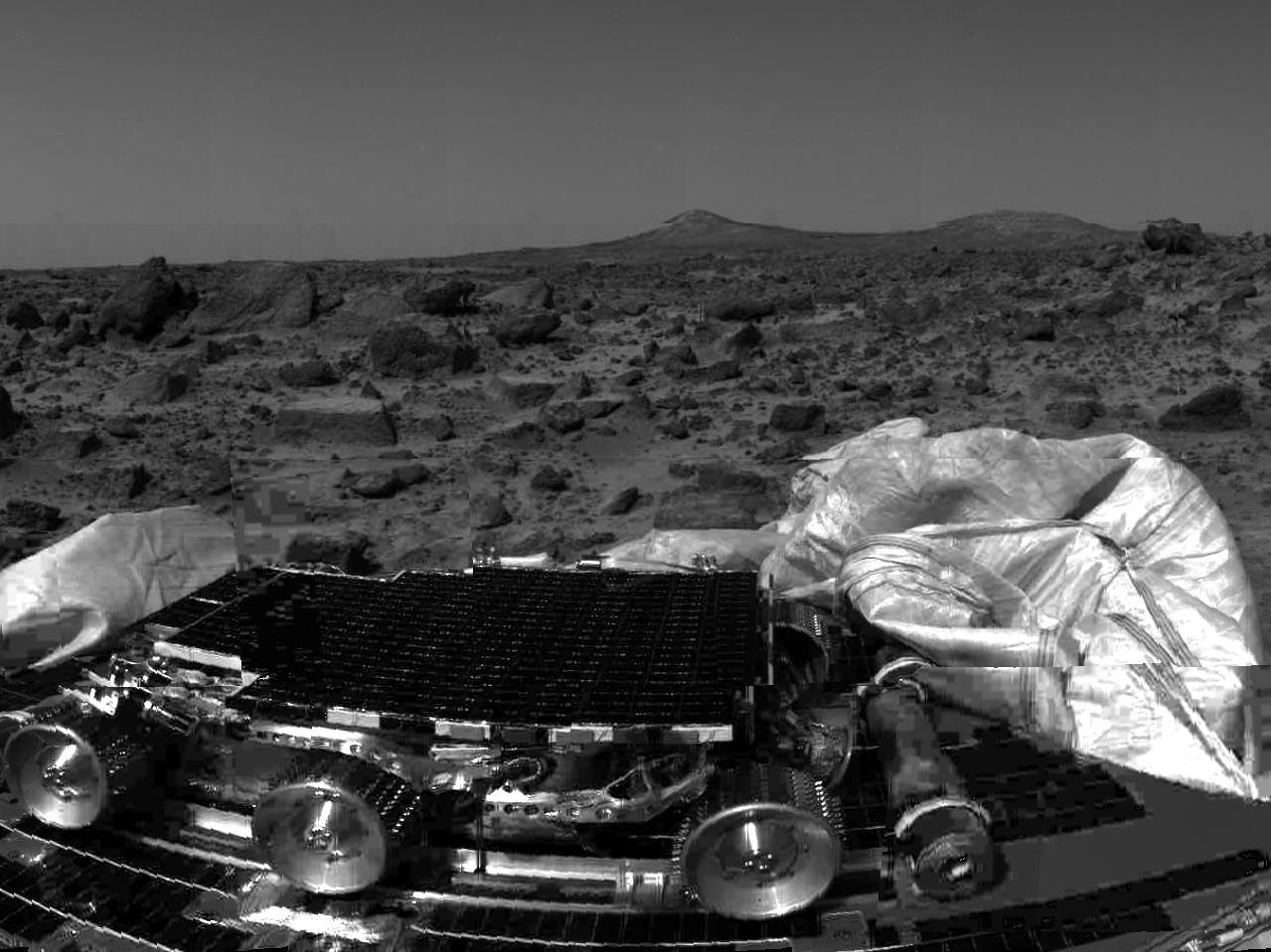 NASA/JPL. Public domain (NASA / US government work).
The problem
Section titled “The problem”A Mars surface vehicle has to drive over unknown terrain it cannot fully see, on a few watts of solar power, in a thin cold atmosphere, and with an Earth link that allows one command cycle per sol [3]. Sojourner was the first vehicle to meet those conditions on Mars.
What has flown
Section titled “What has flown”Overview
Section titled “Overview”Sojourner rode the Mars Pathfinder lander to Ares Vallis and became the first rover to operate on Mars on 4 July 1997 [1], [2]. Planned for seven sols, it returned data and images for 83 [3].
Specifications
Section titled “Specifications”| Parameter | Value | Source |
|---|---|---|
| Mass | 10.5 kg (15.2 kg with lander support equipment) | [3] |
| Height | about 30 cm | [1] |
| Wheels | six, rocker-bogie suspension | [3], [4] |
| Instruments | alpha proton X-ray spectrometer, three cameras | [1] |
Mission profile
Section titled “Mission profile”| Parameter | Value | Source |
|---|---|---|
| Launch | 4 December 1996 UTC, Cape Canaveral | [1], [2] |
| Landing | 4 July 1997, Ares Vallis | [1], [2] |
| Planned mission | seven sols | [3] |
| Surface operations duration | 83 sols | [3] |
| Final data transmission from Pathfinder | 27 September 1997 | [1] |
| Linear distance traversed | approximately 100 m | [3], [2] |
| Average traverse per sol | 2.7 m | [3] |
| APXS in-situ elemental analyses | 16 | [3] |
| Rover camera images | 550 | [2], [1] |
| Environmental measurements | approximately 8.5 million | [2] |
| Total mission data returned | approximately 2.3 Gbit | [2], [1] |
The mission page counts more than 15 chemical analyses of rocks and soil [1], where the rover engineering report gives 16 APXS in-situ analyses [2]. The 83 sols and roughly 104 m of total traverse are far beyond the design life of one week for the rover and one month for the lander, [2].
Pathfinder entered the atmosphere directly, decelerated by heat shield, parachute and retrorockets, and landed inside an airbag cocoon [2]. The project’s own account, filed at about sol 60, gives the entry, descent and landing sequence directly from telemetry: entry deceleration, the altitude of parachute deployment, and the altitudes of rocket ignition and lander separation [5]. Airbag landing is viable at this mass because the atmosphere, at a mean surface density near 0.020 kg/m3, decelerates a light entry vehicle adequately under a parachute alone [6].
Mobility
Section titled “Mobility”The rover masses 10.5 kg on six wheels in a rocker-bogie suspension [3]. The linkage’s proportions were set by solving, at each of several candidate obstacle geometries, the coefficient of friction a wheel needs to climb a vertical face, then choosing link lengths to minimize the worst case: six wheels clear an axle-high wall at a friction coefficient near 0.8, where a four-wheeled layout needs 0.78 to 1.4 depending on which end meets the obstacle [4]. Springs were left out deliberately, because an elastic suspension raises the load on a climbing wheel while unloading the others, the opposite of what obstacle climbing needs [4]; the same passive linkage keeps all six wheels loaded on uneven ground without active leveling. The same geometry, scaled up and re-tested on the Exploration Technology Rover precursor to the Mars Exploration Rovers, has been used on every subsequent NASA Mars rover [7].
Wheel surface speed during instrumented operation was 1 cm/s at approximately 1.2 rpm [3], a rate low enough that wheel-soil interaction is quasi-static and inertial effects in the soil do not enter. Wheel dig-in tests give the only direct in-situ measurement of surface bearing behavior from this mission: in softer soil the test wheel sank 0.6 to 0.7 cm in the first two revolutions and reached 0.8 to 1.2 cm after seven, while in harder material it reached 1.5 cm in two revolutions. Ground tests in analog soils produced depths over 3 cm [3]. Separate wheel-torque shear tests at other sites on the same traverse gave friction angles near 34 to 39 degrees for the cloddy material and 26 to 28 degrees for the loose drift deposits, with small cohesion in both [8]. A companion analysis of twelve wheel-spin experiments derived apparent cohesions of a few tenths of a kilopascal, illustrative rather than tightly bounded [8]. Taken together, the spread reflects the strength range of Martian surface materials, which run from sand at cohesion at or below 1 kPa to indurated soils near 11 kPa [9].
Power and thermal
Section titled “Power and thermal”A solar array on the top surface supplies about 16 W, with non-rechargeable lithium batteries for short night operations [2]. Electronics rode in a warm electronics box lined with silica aerogel, sized with essentially no margin between the predicted flight temperature and the allowable limit beyond the 10 to 15 degC gap to the qualification temperature [10]. Mean surface pressure at the site was 6.7 mbar [2]. In flight the computer and power boards held between about -20 and +40 degC each sol, and the only component that misbehaved was the commercial UHF modem, whose crystals drifted with temperature; the fix was operational, timing transmissions and heating cycles around the sol rather than changing the hardware [1]. Postflight correlation found the preflight thermal model had missed ground-reflected solar flux onto the cameras, worth about 20 percent of the insolation, and a near-surface wind sublayer where effective wind speed is under half of what the lander mast measured [1].
Atmospheric opacity at the landing site was 0.5 during surface operations, with suspended particles of approximately 1 µm [2]. That opacity sits at the top of the background range for the aphelion half of the Martian year, so array output over the 83 sols was near its seasonal floor rather than depressed by a storm [6].
Hazard sensing and the Earth link
Section titled “Hazard sensing and the Earth link”Hazard detection uses two binocular cameras and a laser ranging device; five laser stripes gave twenty elevation estimates 56 to 81 cm ahead, acquired only while the rover was stationary [2]. Neither senses soil strength, and cohesion across Martian surface types varies from at or below 1 kPa for sand to 11 kPa for indurated soil with no corresponding change in relief [9]. The rover has no direct Earth link; all communication relays through the Pathfinder lander over UHF at a raw rate of 9,600 bps, about 2,000 bps effective, out to a 500 m maximum range, which confined the rover to the lander’s vicinity [3]. One-way Earth-Mars signal delay during the mission was at least ten minutes, which forces onboard hazard handling rather than direct teleoperation [3].
Autonomy
Section titled “Autonomy”Commanding was once per sol, so a Go To Waypoint command had to run without oversight for its entire length: the rover drove an approximate straight line, stopped roughly every 7 cm of travel to difference images taken with and without the laser stripes, and dead reckoned position from wheel encoders and a rate gyro, with a measured position error of about 5 to 10 percent of distance traveled, heading drift of roughly 1 to 3 degrees per sol, and an average traverse of 2 to 3 m per sol [3]. Hazard detection kept the vehicle off non-traversable terrain even where dead reckoning alone would not have reached the commanded point; the team also states it withheld the full hazard-avoidance suite on many sols because a bad traverse risked the mission, so the flight numbers understate rather than bound what the software could do [3].
Payload and instruments
Section titled “Payload and instruments”The alpha proton X-ray spectrometer was placed against targets by backing the rover into them, returning the first in-situ measurements of Martian rock composition; 16 analyses were completed [2]. Close-range Sojourner imagery of rounded, centimeter-scale objects and of knob-and-socket textures on nearby rocks was read by the rover team as possibly pebbles freed from conglomerate, an interpretation offered as one of several competing origins rather than established by composition or texture measurements taken at the time [8].
Wheel Abrasion Experiment
Section titled “Wheel Abrasion Experiment”The WAE gave Sojourner a quantitative measure of the abrasiveness of Martian surface material, separate from composition measurements.
| Parameter | Value |
|---|---|
| Location | right center wheel |
| Substrate | black anodized, dye-impregnated aluminum strips, 25 x 120 x 0.25 mm |
| Metals | aluminum, nickel, platinum, resistively evaporation-deposited |
| Film thicknesses on one strip | 200, 300, 450, 700, 1000 Å |
| Brinell hardness of the three metals | Al 16, Pt 64, Ni 100 |
| Sensor | photovoltaic reflectance detector |
| Typical run | 2 revolutions acquiring, 3 not, 2 acquiring; seven total |
| Readings per sample per revolution | five, central reading taken as peak |
| Runs conducted | 11, totaling 55 wheel revolutions, 39 counted as abrasion |
Values from [3].
The metals bracket a hardness range: material that abrades aluminum but not nickel has a hardness between Brinell 16 and 100 [3]. In flight, aluminum wore most and wore inversely with film thickness, while platinum and nickel wore little. The Martian dust is therefore harder than aluminum and softer than nickel [3].
Two experiment modes were run. Rolling wear accumulated during normal driving. At intervals all wheels except the test wheel were locked to hold the rover stationary while the test wheel alone spun into the regolith, producing wear more severe than rolling and the dig-in depths quoted above.
The experiment returned a second result it was not designed for. Electrostatic charging of the wheels attracted dust onto the WAE wheel, which made reflectance interpretation problematic on many runs [3]. Ground tests of a spare WAE wheel in a simulated Martian atmosphere reproduced the effect directly: the wheel picked up dust and developed a measurable electrostatic charge, the charge fell sharply once the wheel was grounded, and the magnitude of charging grew as grain size shrank [3]. The surface-deposit survey ties the same mechanism to the reflective, low-rimmed rover tracks left in material with grains below about 40 µm, rather than in sand [8]. The WAE dust adhesion and the track reflectivity point to the same grain-size threshold [3], [8].
WAE photodetector
Section titled “WAE photodetector”| Parameter | Value |
|---|---|
| Detector | three GaAs-on-Ge solar cells, 2 x 4 mm each |
| Package | 1 cm cube, 10 g mass budget |
| Design / actual operating temperature | -50 C / -30 C |
| Load resistor | 1.26 kΩ at 0.1 percent, against a calculated maximum of 1.275 kΩ |
| Output voltage limit | 250 mV |
| Peak response | 5 pA·cm²/mW at 0 C |
| Short-circuit current at 40 mW/cm² | 196 pA |
| Isc temperature coefficient | 0.067 percent per C |
| Pointing tolerance | ±15 deg |
| Standoff, sample center to detector face | 19.2 mm |
| Imaged sample area | 1.5 x 2.5 cm |
| Landing load qualification | 60 g |
| Low temperature qualification | -110 C, 1 h dwell |
| Bakeout | 110 C minimum, 50 h |
| Vacuum test | below 1 torr, 24 h at 40 C |
Values from [11].
Detector output feeds the reflectance record from which the metal film wear is read. Photocurrent at maximum illumination is 196 pA, so the resistor must be large enough to develop a readable voltage and small enough that the cell stays near short circuit; 1.26 kΩ against a calculated 1.275 kΩ maximum leaves no margin above, and the 250 mV output ceiling is what sets it [11].
Surface conditions measured
Section titled “Surface conditions measured”| Quantity | Value |
|---|---|
| Mean atmospheric pressure | 6.7 mbar, varying 0.2 to 0.3 mbar daily |
| Atmospheric opacity | 0.5 |
| Suspended dust particle size | approximately 1 µm |
| Precipitable water vapor | 0.01 mm |
| Maximum daytime / minimum night temperature | -9 C / -76 C |
| Temperature sensor heights on the lander mast | 25, 50, 100 cm |
Values from [2].
Winds were light and variable relative to the Viking sites: steady from the south at night, rotating clockwise south to west to north to east through the day [2]. Later compilation across all landed sites puts daytime wind maxima and a clockwise diurnal rotation of wind direction as the general low-latitude pattern, driven by convective mixing [6]. Dust devils were detected repeatedly from mid-morning through late afternoon, with marked temperature and pressure signatures as they passed the lander. Those figures sit inside the ranges later compiled across all landed sites, where measured air temperature spans 140 to 300 K and background column dust optical depth stays below 1 outside storm season [6].
Technologies developed
Section titled “Technologies developed”Rocker-bogie mobility, onboard hazard avoidance from stereo plus laser ranging, and the sol-by-sol command cycle were all first flown here and are carried by every later Mars surface mission [3], [7]. The dig-in depths it measured, 0.6 to 1.5 cm depending on material, are the earliest in-situ constraint on the bearing behavior later quantified as cohesion at or below 1 kPa for sand and up to 11 kPa for indurated soils [9]. The autonomy split it recorded, weak dead reckoning against workable hazard avoidance, set the target the next generation of Mars rovers designed against: roughly 100 m of autonomous traverse per sol, about what Sojourner covered across its entire mission [3].
The Wheel Abrasion Experiment established a method of using the rover’s own wheel as a tribometer, with a graded set of metal films as the calibrated reference, to bracket the hardness of the surface material. It cost 10 g of detector and one modified wheel [11]. It also detected electrostatic charging of the wheel and a grain size limit on the effect [3], [8].
What is being tried now
Section titled “What is being tried now”The paragraphs below place Sojourner’s single design point against later flown systems first, then against work that has been tested on the ground or only proposed.
Flown successors and their approaches
Section titled “Flown successors and their approaches”Sojourner flew one point in a wider design space for each rover function, and later work is easiest to read against that point.
Localization. Sojourner dead reckoned from wheel encoders and a rate gyro [3]. A 1997 survey of visual localization graded three alternatives by scale: recognition of the rover in lander stereo imagery (150 trials at 2 to 10 m gave a mean downrange bias of 8.32 percent with 6.66 percent standard deviation), elevation map matching (about 3 cm average absolute error over a 12-image Mars Yard sequence), and descent-image matching, whose precision figures are predictions from idealized geometry rather than measurements [13]. These are test results, not flight results. The Rocky 7 prototype was field tested in 1997 at Lavic Lake with a sun sensor for heading, compared against the gyro and odometry scheme used on Sojourner; the sun sensor was miscalibrated during the test, so its reported 6 percent and 3.4 degree figure is degraded, and the test covered one rover on three traverses [20]. A slip-compensating path follower fusing visual odometry, an IMU and six-wheel kinematics was later shown on a rocker-bogie testbed against a total station, again a field test and not flight [27]. Visual odometry did fly on the Mars Exploration Rovers, 792 m of Spirit’s 4798 m and 682 m of Opportunity’s 5947 m, about 14 percent of distance [30].
Hazard avoidance and path selection. Sojourner stopped and imaged laser stripes, a stationary, once-per-sol scheme [2], [3]. A fuzzy-logic alternative combining goal-seeking, terrain-traversing and collision-avoidance behaviors was evaluated only in the authors’ simulator on three hand-built scenes, so its claimed superiority over other planners is not supported by that evidence [21]. On MER, autonomous terrain assessment and local path selection covered 1354 of Spirit’s 4798 m and 1379 of Opportunity’s 5947 m, about 25 percent of distance [30]. The cost of that autonomy is stated in a JPL briefing that tabulates Sojourner, Spirit and Opportunity side by side: blind driving ran about 120 m/hr, hazard avoidance 10 to 35 m/hr, visual odometry 10 m/hr, and both together 5 m/hr [12]. The MER flight software wrapped goal-based driving in three classes of check: command limits, reactive checks such as motor current and tilt, and predictive checks from terrain assessment [29].
Mobility and terrain interaction. The rocker-bogie geometry flown on Sojourner [4] was reworked for MER, where the suspension folds at three joint types and six latches all had to engage on Mars; both rovers deployed with all six verified [15]. The MER mobility assembly was characterized on a 16 foot tilt table over 200 trials on a high-friction mat and six inches of dry loose sand, which gave a slip versus slope curve nearly linear below about 10 degrees on sand; those surfaces were chosen as bounds, not as Mars analogs [14]. For Curiosity, soil properties were inferred by fitting a wheel-terrain simulation to sinkage and slip over the first 360 sols and 1,828 m, so cohesion and friction angle are non-unique fit values and not measurements [28]. Sojourner’s wheel dig-in tests and shear tests [3], [8] are direct in-situ measurements of the same quantities at a much smaller scale. Wheel durability is the failure mode Sojourner’s 100 m could not expose: Curiosity wheel tears were imaged from sol 411 and sol 1315, attributed to ventifact impacts combined with dynamic rocker-bogie loads, and mitigated by driving backward on hard terrain and avoiding ventifacts [25]. A Scarecrow campaign in the JPL Mars Yard tested driving on the outer rim alone, using a mass surrogate whose absolute slip is not Curiosity’s [26]. Curiosity’s first seven years cover 21,318.5 m through sol 2488, with 15.7 percent of attempted drives ending early and 91.7 percent of predicted cumulative odometry still achieved [24].
Operations and survey context. Sojourner’s one-plan-per-sol cycle [3] became the MER tactical process, which was already built to replan a failed drive each day, so anomalies took under 5 percent of surface time, about 30 of 700 sols per vehicle [16]. A 2003 NASA-commissioned survey of space robotics drew its flight numbers only from Sojourner and the pre-landing MER, and its forecasts are respondent consensus [22]. A 2007 JPL section briefing places the MER, Phoenix and MSL flight contributions beside steep-terrain concepts (Axel, ClimbBot, ATHLETE, LEMUR) that have not flown [23].
Hardware qualification. The rover’s brush motors and cells set the reference for later work. Long-life DC brush motors for the MVACS robotic arm were compared across air, vacuum, CO2 and N2 at -70 to -80 C, in a report that cites the 100 m Sojourner primary mission as its baseline [17]. Li-ion cells for a terrestrial tactical robot were characterized on five cells in total, so temperature cycle-life data rest on one cell per temperature [18]. MER thermal cycling of flight-candidate hardware is documented only as slides listing cycle counts and temperature ranges, without pass or fail tables [19]. Sojourner’s own thermal experience, warm electronics box and no margin beyond the qualification gap, is recorded in [10].
Perseverance autonomy and operations (flown)
Section titled “Perseverance autonomy and operations (flown)”ENav, the Perseverance autonomous driving algorithm, uses two-stage path selection and a conservative kinematic-settling collision check on a single-core CPU with FPGA-accelerated stereo; through sol 1312 (28 October 2024) it logged 32.1 km at an average 92 m/h [32]. During the Jezero rim ascent (sols 1267 to 1720) slip above 94 percent on 20 degree slopes and featureless terrain defeating visual odometry bounded autonomous driving, and a non radiation hardened Snapdragon co-processor flew for the first time inside a rover onboard safety assessment [33]. An onboard scheduler, the Mars 2020 Simple Planner, was deployed on 5 October 2023 with an offline runtime budget of 30 s estimated and 60 s hard limit [34]. A JPL operations briefing reports that Perseverance drives 90 percent autonomously and that the scheduler saves roughly 10 percent energy, round figures with no stated sample [36]. The same briefing describes ROCAS, a three-part lunar autonomy stack, which is a concept with no test results [36]. A 2026 slide deck reports the first AI-planned waypoints, flown on sols 1707 to 1709, with no success rate or distance printed [31]. Cataloged anomalies cost the six NASA Mars surface missions 11 percent of prime mission duration on average (6.6 percent over the full mission), with a mean anomaly length of 15 sols [35].
Ground-tested and proposed approaches
Section titled “Ground-tested and proposed approaches”Terrain-aware autonomy is the largest group. ESA-funded rock detection (FASTNAV, a YOLOv8n detector) and terrain classification were field tested at Bardenas Reales, with the TRL asserted rather than shown [37]. A self-supervised camera plus LiDAR costmap predictor was trained on Mars-like simulation and tested only on an Earth rover [43]. A legged scout estimates regolith strength from leg forces and feeds a traversal risk map, tested in a lab simulant and on White Sands dunes; it underestimated tamped strength (1.80 against 5.07 N/cm3) [45]. A fused orbital and surface terrain mesh, Landform, is a flown ground-data product for Mars 2020 with a 4 to 8 hour build time [38].
Wheels and locomotion are the second group, and wheel wear is where Sojourner’s roughly 100 m of traverse could not speak [3]. Motion planning that penalizes steering to reduce wheel wear is simulation only, with success falling from 71 to 58 percent when terrain-aware costs were added [39]. A redesigned rimless spoke for the SCOUT lava-tube rover had one field deployment in a Lanzarote lava tube in 2024 and no instrumented campaign [40]. Rut profiles from a Rashid-model grouser wheel were scanned at loads of 25, 40 and 65 N in one sand, nine runs in all, with LiDAR deviations up to 3.20 mm of the same order as the features [41]. A reinforcement-learned controller for the 75 kg ERNEST rover with an active gimbal suspension cut cost of transport 37 percent on one 20 degree simulant slope, a field demonstration and not a flight [42]. Joint Bayesian optimization of wheel geometry and steering gains over 3,000 simulations showed no strategy better, and its three printed wheels support only rank order [44].
The numbers, recent flight statistics
Section titled “The numbers, recent flight statistics”| Quantity | Value | Source |
|---|---|---|
| Perseverance autonomous distance through sol 1312 | 32.1 km at 92 m/h average | [32] |
| Share of Perseverance driving done autonomously | 90 percent | [36] |
| Onboard scheduler runtime budget | 30 s estimated, 60 s hard limit | [34] |
| Prime mission time lost to major anomalies | 11 percent average over six missions | [35] |
| Slip on 20 degree slope, Jezero rim | above 94 percent | [33] |
What is not established
Section titled “What is not established”The soil-mechanics cohesion figures derived from wheel-spin experiments rest on an assumption, that the friction angle equals a photographically measured angle of repose, that the same analysis’s own least-squares fits do not consistently satisfy, so the reported cohesions of a few tenths of a kilopascal should be read as illustrative rather than as a tight bound; bulk density for the site was never measured directly, but inferred from friction angle through a correlation built for lunar soils and simulants and applied here without an error estimate [8]. The conglomerate origin proposed for the rounded surface objects is one of several competing explanations offered from imagery alone, with no compositional or textural measurement to distinguish among them [8]. The operations figures for traverse rate and dead reckoning error come from a single mission on one vehicle at one site, reported by the mission’s own engineers rather than measured against an independent baseline [3].
References
- (2017). NASA: Mars Pathfinder. science.nasa.gov/mission/mars-pathfinder
BibTeX
@misc{nasamars3, title = {NASA: Mars Pathfinder}, organization = {science.nasa.gov}, year = {2017}, url = {https://science.nasa.gov/mission/mars-pathfinder/} } - Golombek, M. P., Anderson, R. C., Barnes, J. R., Bell, J. F., Bridges, N. T., Britt, D. T., Brückner, J., Cook, R. A., Crisp, D., Crisp, J. A., Economou, T., Folkner, W. M., Greeley, R., Haberle, R. M., Hargraves, R. B., Harris, J. A., Haldemann, A. F. C., Herkenhoff, K. E., Hviid, S. F., Jaumann, R., Johnson, J. R., Kallemeyn, P. H., Keller, H. U., Kirk, R. L., Knudsen, J. M., Larsen, S., Lemmon, M. T., Madsen, M. B., Magalhães, J. A., Maki, J. N., Malin, M. C., Manning, R. M., Matijevic, J., McSween, H. Y., Moore, H. J., Murchie, S. L., Murphy, J. R., Parker, T. J., Rieder, R., Rivellini, T. P., Schofield, J. T., Seiff, A., Singer, R. B., Smith, P. H., Soderblom, L. A., Spencer, D. A., Stoker, C. R., Sullivan, R., Thomas, N., Thurman, S. W., Tomasko, M. G., Vaughan, R. M., Wänke, H., Ward, A. W. and Wilson, G. R. (1999). Overview of the Mars Pathfinder Mission: Launch through landing, surface operations, data sets, and science results
. Space Science Reviews, E4. Source
BibTeX
@article{golombek1999overview, title = {Overview of the Mars Pathfinder Mission: Launch through landing, surface operations, data sets, and science results}, author = {Golombek, Matthew P. and Anderson, R. C. and Barnes, J. R. and Bell, J. F. and Bridges, Nathan T. and Britt, Daniel T. and Brückner, J. and Cook, Richard A. and Crisp, D. and Crisp, Joy A. and Economou, T. and Folkner, W. M. and Greeley, R. and Haberle, R. M. and Hargraves, R. B. and Harris, J. A. and Haldemann, Albert F. C. and Herkenhoff, K. E. and Hviid, S. F. and Jaumann, Ralf and Johnson, Jeffrey R. and Kallemeyn, P. H. and Keller, Horst Uwe and Kirk, Randolph L. and Knudsen, J. M. and Larsen, S. and Lemmon, Mark T. and Madsen, M. B. and Magalhães, J. A. and Maki, Justin N. and Malin, Michal C. and Manning, Robert M. and Matijevic, J. and McSween, H. Y. and Moore, Henry J. and Murchie, Scott L. and Murphy, J. R. and Parker, Timothy J. and Rieder, R. and Rivellini, T. P. and Schofield, John T. and Seiff, A. and Singer, R. B. and Smith, Peter H. and Soderblom, L. A. and Spencer, David A. and Stoker, Carol R. and Sullivan, R. and Thomas, N. and Thurman, Sam W. and Tomasko, M. G. and Vaughan, R. M. and Wänke, H. and Ward, A. W. and Wilson, G. R.}, journal = {Space Science Reviews}, volume = {104}, number = {E4}, pages = {8523-8553}, publisher = {American Geophysical Union (AGU)}, year = {1999}, doi = {10.1029/98je02554}, abstract = {Mars Pathfinder successfully landed at Ares Vallis on July 4, 1997, deployed and navigated a small rover about 100 m clockwise around the lander, and collected data from three science instruments and ten technology experiments. The mission operated for three months and returned 2.3 Gbits of data, including over 16,500 lander and 550 rover images, 16 chemical analyses of rocks and soil, and 8.5 million individual temperature, pressure and wind measurements. Path‐finder is the best known location on Mars, having been clearly identified with respect to other features on the surface by correlating five prominent horizon features and two small craters in lander images with those in high‐resolution orbiter images and in inertial space from two‐way ranging and Doppler tracking. Tracking of the lander has fixed the spin pole of Mars, determined the precession rate since Viking 20 years ago, and indicates a polar moment of inertia, which constrains a central metallic core to be between 1300 and ∼2000 km in radius. Dark rocks appear to be high in silica and geochemically similar to anorogenic andesites; lighter rocks are richer in sulfur and lower in silica, consistent with being coated with various amounts of dust. Rover and lander images show rocks with a variety of morphologies, fabrics and textures, suggesting a variety of rock types are present. Rounded pebbles and cobbles on the surface as well as rounded bumps and pits on some rocks indicate these rocks may be conglomerates (although other explanations are also possible), which almost definitely require liquid water to form and a warmer and wetter past. Air‐borne dust is composed of composite silicate particles with a small fraction of a highly magnetic mineral, interpreted to be most likely maghemite; explanations suggest iron was dissolved from crustal materials during an active hydrologic cycle with maghemite freeze dried onto silicate dust grains. Remote sensing data at a scale of a kilometer or greater and an Earth analog correctly predicted a rocky plain safe for landing and roving with a variety of rocks deposited by catstrophic floods, which are relatively dust free. The surface appears to have changed little since it formed billions of years ago, with the exception that eolian activity may have deflated the surface by ∼3–7 cm, sculpted wind tails, collected sand into dunes, and eroded ventifacts (fluted and grooved rocks). Pathfinder found a dusty lower atmosphere, early morning water ice clouds, and morning near‐surface air temperatures that changed abruptly with time and height. Small scale vortices, interpreted to be dust devils, were observed repeatedly in the afternoon by the meteorology instruments and have been imaged.} } - Keith, T. G. and Siebert, M. W. (1998). Mars Pathfinder Wheel Abrasion Experiment Ground Test, and Mars Pathfinder Final Technical Report
. NASA Lewis Research Center and Jet Propulsion Laboratory. Source
BibTeX
@techreport{keith1998mars, title = {Mars Pathfinder Wheel Abrasion Experiment Ground Test, and Mars Pathfinder Final Technical Report}, author = {Keith, Theo G. and Siebert, Mark W.}, institution = {NASA Lewis Research Center and Jet Propulsion Laboratory}, year = {1998}, url = {https://ntrs.nasa.gov/citations/19990013984}, abstract = {The National Aeronautics and Space Administration (NASA) sent a mission to the martian surface, called Mars Pathfinder. The mission payload consisted of a lander and a rover. The primary purpose of the mission was demonstrating a novel entry, descent, and landing method that included a heat shield, a parachute, rockets, and a cocoon of giant air bags. Once on the surface, the spacecraft returned temperature measurements near the Martian surface, atmosphere pressure, wind speed measurements, and images from the lander and rover. The rover obtained 16 elemental measurements of rocks and soils, performed soil-mechanics, atmospheric sedimentation measurements, and soil abrasiveness measurements.} } - Bickler, D. B. (1997). The Mars Rover Mobility System
. JPL Open Repository. Source
BibTeX
@inproceedings{bickler1997mars, title = {The Mars Rover Mobility System}, author = {Bickler, Donald B.}, publisher = {JPL Open Repository}, year = {1997}, url = {https://dataverse.jpl.nasa.gov/dataset.xhtml?persistentId=hdl:2014/18908} } - Cook, R. A. and Spear, A. J. (1997). Back to Mars: The Mars Pathfinder Mission
. Acta Astronautica, 4-10. Source
BibTeX
@article{cook1997back, title = {Back to Mars: The Mars Pathfinder Mission}, author = {Cook, Richard A. and Spear, Anthony J.}, journal = {Acta Astronautica}, volume = {41}, number = {4-10}, pages = {599-608}, year = {1997}, doi = {10.1016/s0094-5765(98)00069-1} } - Martínez, G. M., Newman, C. N., De Vicente-Retortillo, A., Fischer, E., Renno, N. O., Richardson, M. I., Fairén, A. G., Genzer, M., Guzewich, S. D., Haberle, R. M., Harri, A.-M., Kemppinen, O., Lemmon, M. T., Smith, M. D., de la Torre-Juárez, M. and Vasavada, A. R. (2017). The Modern Near-Surface Martian Climate: A Review of In-situ Meteorological Data from Viking to Curiosity
. Space Science Reviews. Source
BibTeX
@article{martinez2017modern, title = {The Modern Near-Surface Martian Climate: A Review of In-situ Meteorological Data from Viking to Curiosity}, author = {Martínez, G. M. and Newman, C. N. and De Vicente-Retortillo, A. and Fischer, Erik and Renno, N. O. and Richardson, Mark I. and Fairén, A. G. and Genzer, Maria and Guzewich, Scott D. and Haberle, R. M. and Harri, Ari-Matti and Kemppinen, Osku and Lemmon, Mark T. and Smith, Michael D. and de la Torre-Juárez, M. and Vasavada, Ashwin R.}, journal = {Space Science Reviews}, volume = {212}, pages = {295--338}, year = {2017}, doi = {10.1007/s11214-017-0360-x}, abstract = {We analyze the complete set of in-situ meteorological data obtained from the Viking landers in the 1970s to today’s Curiosity rover to review our understanding of the modern near-surface climate of Mars, with focus on the dust, CO 2 and H 2 O cycles and their impact on the radiative and thermodynamic conditions near the surface. In particular, we provide values of the highest confidence possible for atmospheric opacity, atmospheric pressure, near-surface air temperature, ground temperature, near-surface wind speed and direction, and near-surface air relative humidity and water vapor content. Then, we study the diurnal, seasonal and interannual variability of these quantities over a span of more than twenty Martian years. Finally, we propose measurements to improve our understanding of the Martian dust and H 2 O cycles, and discuss the potential for liquid water formation under Mars’ present day conditions and its implications for future Mars missions. Understanding the modern Martian climate is important to determine if Mars could have the conditions to support life and to prepare for future human exploration.} } - Lindemann, R., Reid, L. K. and Voorhees, C. (1999). Mobility Sub-System for the Exploration Technology Rover
. JPL Open Repository. Source
BibTeX
@inproceedings{lindemann1999mobility, title = {Mobility Sub-System for the Exploration Technology Rover}, author = {Lindemann, R. and Reid, Lisa K. and Voorhees, C.}, publisher = {JPL Open Repository}, year = {1999}, url = {https://dataverse.jpl.nasa.gov/dataset.xhtml?persistentId=hdl:2014/17115} } - Matijevic, J. (1997). Characterization of the Martian Surface Deposits by the Mars Pathfinder Rover, Sojourner
. AIAA/AAS Astrodynamics Specialist Conference. Source
BibTeX
@inproceedings{matijevic1997characterization, title = {Characterization of the Martian Surface Deposits by the Mars Pathfinder Rover, Sojourner}, author = {Matijevic, J.}, booktitle = {AIAA/AAS Astrodynamics Specialist Conference}, volume = {278}, pages = {1765-1768}, publisher = {JPL Open Repository}, year = {1997}, doi = {10.1126/science.278.5344.1765}, abstract = {Sojourner, the Mars Pathfinder rover, discovered pebbles on the surface and in rocks that may be sedimentary—not volcanic—in origin. Surface pebbles may have been rounded by Ares flood waters or liberated by weathering of sedimentary rocks called conglomerates. Conglomerates imply that water existed elsewhere and earlier than the Ares flood. Most soil-like deposits are similar to moderately dense soils on Earth. Small amounts of dust are currently settling from the atmosphere.} } - Spohn, T., Hudson, T. L., Witte, L., Wippermann, T., Wisniewski, L., Kedziora, B., Vrettos, C., Lorenz, R. D., Golombek, M., Lichtenheldt, R., Grott, M., Knollenberg, J., Krause, C., Fantinati, C., Krueger, T. and Grygorczuk, J. (2022). The InSight-HP3 Mole on Mars: Lessons Learned from Attempts to Penetrate to Depth in the Martian Soil
. Advances in Space Research, 8. Source
BibTeX
@article{spohn2022insight, title = {The InSight-HP3 Mole on Mars: Lessons Learned from Attempts to Penetrate to Depth in the Martian Soil}, author = {Spohn, Tilman and Hudson, Troy L. and Witte, Lars and Wippermann, Torben and Wisniewski, Lukasz and Kedziora, Bartosz and Vrettos, Christos and Lorenz, Ralph D. and Golombek, Matthew and Lichtenheldt, Roy and Grott, Matthias and Knollenberg, Joerg and Krause, Christian and Fantinati, Cinzia and Krueger, Torsten and Grygorczuk, Jerzy}, journal = {Advances in Space Research}, volume = {69}, number = {8}, pages = {3140--3163}, year = {2022}, doi = {10.1016/j.asr.2022.02.009}, abstract = {The NASA InSight lander mission to Mars payload includes the Heat Flow and Physical Properties Package HP3 to measure the surface heat flow. The package was designed to use a small penetrator - nicknamed the mole - to implement a vertical string of temperature sensors in the soil to a depth of 5 m. The mole itself is equipped with sensors to measure a thermal conductivity-depth profile as it proceeds to depth. The heat flow is calculated from the product of the temperature gradient and the thermal conductivity. To avoid the perturbation caused by annual surface temperature variations, the measurements need to be taken at a depth between 3 m and 5 m. The mole is designed to penetrate cohesionless soil similar in rheology to quartz sand which is expected to provide a good analogue material for Martian sand. The sand would provide friction to the buried mole hull to balance the remaining recoil of the mole hammer mechanism that drives the mole forward. Unfortunately, the mole did not penetrate more than 40 cm, roughly a mole length. The failure to penetrate deeper is largely due to a cohesive duricrust of a few tens of centimeter thickness that failed to provide the required friction. Although a suppressor mass and spring as part of the mole hammer mechanism absorb much of the recoil, the available mass did not allow designing a system that fully eliminated the recoil. The mole penetrated to 40 cm depth benefiting from friction provided by springs in the support structure from which it was deployed and from friction and direct support provided by the InSight Instrument Deployment Arm. In addition, the Martian soil provided unexpected levels of penetration resistance that would have motivated designing a more powerful mole. The low weight of the mole support structure was not sufficient to guide the mole penetrating vertically. Roughly doubling the overall mass of the instrument package would have allowed to design a more robust system with little or no recoil, more energy of the mole hammer mechanism and a more massive support structure. In addition, to cope with duricrust a mechanism to support the mole to a depth of about two mole lengths should be considered.} } - Eisen, H., Wen, L. C., Hickey, G. S. and Braun, D. F. (1998). Sojourner Mars Rover Thermal Performance
. SAE Technical Paper Series. Source
BibTeX
@inproceedings{eisen1998sojourner, title = {Sojourner Mars Rover Thermal Performance}, author = {Eisen, H. and Wen, L. C. and Hickey, Gregory S. and Braun, David F.}, booktitle = {SAE Technical Paper Series}, volume = {1}, publisher = {SAE International}, year = {1998}, doi = {10.4271/981685}, abstract = {<div class="htmlview paragraph">The Sojourner Rover landed on the surface of Mars on July 4, 1997 as part of the Mars Pathfinder Mission. The mission lasted almost three months during which the thermal design of the Rover was tested. This paper summarizes the Rover's design and performance as well as post-mission model correlation.</div>} } - Wilt, D. M., Ferguson, D. C. and Siebert, M. W. (1997). Photodetector Development for the Wheel Abrasion Experiment on the Sojourner Microrover of the Mars Pathfinder Mission
. Intersociety Energy Conversion Engineering Conference, NASA TM-113123. Source
BibTeX
@inproceedings{wilt1997photodetector, title = {Photodetector Development for the Wheel Abrasion Experiment on the Sojourner Microrover of the Mars Pathfinder Mission}, author = {Wilt, D. M. and Ferguson, D. C. and Siebert, Mark W.}, booktitle = {Intersociety Energy Conversion Engineering Conference}, volume = {1}, number = {NASA TM-113123}, pages = {738-742}, institution = {NASA Lewis Research Center}, year = {1997}, doi = {10.1109/iecec.1997.659283}, abstract = {On-board the Mars Pathfinder spacecraft, launched in December of 1996, is a small roving vehicle named Sojourner. On Sojourner is an experiment to determine the abrasive characteristics of the Martian surface, called the Wheel Abrasion Experiment (WAE). The experiment works as follows: one of the wheels of the rover has a strip of black anodized aluminum bonded to the tread. The aluminum strip has thin coatings of aluminum, nickel and platinum deposited in patches. There are five patches or samples of each metal, and the patches range in thickness from 200 /spl Aring/ to 1000 /spl Aring/. The different metals were chosen for their differing hardness and their environmental stability. As the wheel is spun in the Martian soil, the thin patches of metal are abraded away, exposing the black anodization. The abrasion is monitored by measuring the amount of light reflected off of the samples. A photodetector was developed for this purpose, and that is the subject of this paper.} } - Maimone, M. W. (2009). Planetary Rover Systems: Sojourner to MSL, 20150011982. ntrs.nasa.gov/citations/20150011982
BibTeX
@misc{maimone2009planetary, title = {Planetary Rover Systems: {Sojourner} to {MSL}}, author = {Maimone, Mark W.}, howpublished = {Presentation at the Jet Propulsion Laboratory, California Institute of Technology}, number = {20150011982}, year = {2009}, url = {https://ntrs.nasa.gov/citations/20150011982}, abstract = {No abstract available} } - Matthies, L. H., Olson, C. F., Tharp, G. and Laubach, S. (1997). Visual Localization Methods for Mars Rovers using Lander, Rover, and Descent Imagery
. International Symposium on Artificial Intelligence, Robotics and Automation in Space. Source
BibTeX
@inproceedings{matthies1997visual, title = {Visual Localization Methods for Mars Rovers using Lander, Rover, and Descent Imagery}, author = {Matthies, Larry H. and Olson, Clark F. and Tharp, Greg and Laubach, Sharon}, booktitle = {International Symposium on Artificial Intelligence, Robotics and Automation in Space}, address = {Tokyo, Japan}, year = {1997}, url = {https://dataverse.jpl.nasa.gov/dataset.xhtml?persistentId=hdl:2014/22227} } - Lindemann, R. A. and Voorhees, C. J. (2005). Mars Exploration Rover mobility assembly design, test and performance
. IEEE International Conference on Systems, Man and Cybernetics. Source
BibTeX
@inproceedings{lindemann2005mars, title = {Mars Exploration Rover mobility assembly design, test and performance}, author = {Lindemann, Randel A. and Voorhees, Chris J.}, booktitle = {IEEE International Conference on Systems, Man and Cybernetics}, volume = {1}, pages = {450-455}, publisher = {IEEE}, year = {2005}, doi = {10.1109/icsmc.2005.1571187}, abstract = {In January 2004, NASA landed two mobile robotic spacecraft, or rovers, on opposite sides of the planet Mars. These rovers, named Spirit and Opportunity, were each sent on their own scientific mission of exploration. Their objective was to work as robotic geologists. After more than a year the vehicles are still in excellent health, and returning vast amounts of scientific information on the ancient water processes that helped form Mars. Key to the success of the rovers was the development of their advanced mobility system. In this paper the mobility assembly, the mechanical hardware that determines the vehicles mobility capability, is described. The details of the design, test, and performance of the mobility assembly are shown to exceed the mission requirements. The rovers' ability to traverse the Mars terrain with its combination of rocks, craters, soft soils, and hills was verified, and the system design validated.} } - Harrington, B. D. and Voorhees, C. (2004). The challenges of designing the rocker-bogie suspension for the Mars Exploration Rover
. JPL Open Repository. Source
BibTeX
@inproceedings{harrington2004challenges, title = {The challenges of designing the rocker-bogie suspension for the Mars Exploration Rover}, author = {Harrington, Brian D. and Voorhees, Chris}, publisher = {JPL Open Repository}, year = {2004}, url = {https://dataverse.jpl.nasa.gov/dataset.xhtml?persistentId=hdl:2014/38435} } - Matijevic, J. and Dewell, E. (2005). Anomaly Recovery and the Mars Exploration Rovers
. SpaceOps Conference. Source
BibTeX
@inproceedings{matijevic2005anomaly, title = {Anomaly Recovery and the Mars Exploration Rovers}, author = {Matijevic, Jacob and Dewell, Emily}, booktitle = {SpaceOps Conference}, year = {2005}, doi = {10.2514/6.2006-5957}, abstract = {The premise of the design of operations for the Mars Exploration Rovers (MER) is that the vehicles will drive each day. As a result, they will encounter some aspect of the terrain environment that cannot be anticipated or otherwise accommodated by the sequences linked onboard that day. The operations team then must correct the problem by planning then commanding the execution of a different drive the next day. Often other aspects of the operation on the surface of Mars: environmental changes, component degradation, errors in sequence design or execution, etc., lead to anomalies which must be addressed before normal operations can resume. The operational design that makes it possible to recover from a driving error each day also reduces the time needed to recover from anomalies. As an example of the efficiency achieved, less than 5% (about 30 sols out of 700 sols of operations) of the time on the surface has been devoted to recovery from anomalies for each vehicle. In this paper the major anomalies experienced by the MER rovers will be recounted and the streamlined approaches to addressing these problems described. The operational flexibility developed for these missions is also a function of the system design that anticipated a number of likely faults and conditions arising from uncertainty in sequence execution and environmental change. This design will be described as well as the considerations in operation that motivated this design. These considerations will likely be present in any future surface mission.} } - Noon, D. E. and Braun, D. (1998). Long Life DC brush motor for use on the Mars Surveyor Program
. Jet Propulsion Laboratory, 20210003097. Source
BibTeX
@techreport{noon1998long, title = {Long Life DC brush motor for use on the Mars Surveyor Program}, author = {Noon, Don E. and Braun, D.}, number = {20210003097}, institution = {Jet Propulsion Laboratory}, year = {1998}, url = {https://ntrs.nasa.gov/citations/20210003097}, abstract = {DC brush motors have several qualities which make them very attractive for space flight applications.} } - Chin, K. B., Smart, M. C., Narayanan, S. R., Ratnakumar, B. V., Whitcanack, L. D., Davies, E. D., Surampudi, S. and Raman, N. S. (2003). Li-ion cells for terrestrial robots
. Conference of Electrochemical Society. Source
BibTeX
@inproceedings{chin2003li, title = {Li-ion cells for terrestrial robots}, author = {Chin, Keith B. and Smart, M. C. and Narayanan, S. R. and Ratnakumar, B. V. and Whitcanack, L. D. and Davies, E. D. and Surampudi, S. and Raman, N. S.}, booktitle = {Conference of Electrochemical Society}, year = {2003}, url = {https://ntrs.nasa.gov/citations/20060043910}, abstract = {SAFT prismatic wound 5 Ahr MP series cells were evaluated for potential application in a lithium ion battery designed for Tactical Mobile Robots (TMR). In order to satisfy battery design requirements, a 10 Ahr battery containing two parallel 8-cell strings was proposed. The proposed battery has a weight and volume of approximately 3.2kg and 1.6 liters, respectively. Cell qualification procedures include initial characterization, followed by charge/discharge cycling at 100% DOD with intermittent EIS measurements at various state of charge. Certain cells were also subjected to extreme operational temperatures for worst-case analysis. Excellent specific energy (>130 Whr/kg) was obtained with initial characterization cycles. Even at abusive thermal conditions, the cell capacity fade was less than Ahr after 300 cycles. Rate characterization showed good cell discharge behavior with minimal decrease in capacity. At various state of charge, impedance measurements suggest that the cathode play a more significant role in capacity. At various state of charge impedance measurements suggest that the cathode play a more significant role in capacity fade than the anode.} } - Ramesham, R. (2004). Extreme temperature thermal cycling tests and results to assess reliability for Mars rover flight qualification. dataverse.jpl.nasa.gov/dataset.xhtml
BibTeX
@misc{ramesham2004extreme, title = {Extreme temperature thermal cycling tests and results to assess reliability for Mars rover flight qualification}, author = {Ramesham, Rajeshuni}, year = {2004}, url = {https://dataverse.jpl.nasa.gov/dataset.xhtml?persistentId=hdl:2014/38244} } - Seraji, H. and Bon, B. (1998). Autonomous Navigation of Planetary Rovers: A Fuzzy Logic Approach
. AIAA Gossamer Systems Forum. Source
BibTeX
@inproceedings{seraji1998autonomous, title = {Autonomous Navigation of Planetary Rovers: A Fuzzy Logic Approach}, author = {Seraji, Homayoun and Bon, Bruce}, booktitle = {AIAA Gossamer Systems Forum}, publisher = {JPL Open Repository}, year = {1998}, url = {https://dataverse.jpl.nasa.gov/dataset.xhtml?persistentId=hdl:2014/16740} } - Pedersen, L., Kortenkamp, D., Wettergreen, D. and Nourbakhsh, I. (2003). A Survey of Space Robotics
. International Symposium on Artificial Intelligence, Robotics and Automation in Space. Source
BibTeX
@inproceedings{pedersen2003survey, title = {A Survey of Space Robotics}, author = {Pedersen, L and Kortenkamp, D and Wettergreen, D and Nourbakhsh, I}, booktitle = {International Symposium on Artificial Intelligence, Robotics and Automation in Space}, year = {2003}, url = {https://ntrs.nasa.gov/citations/20030054507}, abstract = {In this paper we summarize a survey conducted by NASA to determine the state-of-the-art in space robotics and to predict future robotic capabilities under either nominal and intensive development effort. The space robotics assessment study examined both in-space operations including assembly, inspection, and maintenance and planetary surface operations like mobility and exploration. Applications of robotic autonomy and human-robot cooperation were considered. The study group devised a decomposition of robotic capabilities and then suggested metrics to specify the technical challenges associated with each. The conclusion of this paper identifies possible areas in which investment in space robotics could lead to significant advances of important technologies.} } - Volpe, R. A. (2007). Robotic space exploration technology development and mission infusion. dataverse.jpl.nasa.gov/dataset.xhtml
BibTeX
@misc{volpe2007robotic, title = {Robotic space exploration technology development and mission infusion}, author = {Volpe, Richard A.}, year = {2007}, url = {https://dataverse.jpl.nasa.gov/dataset.xhtml?persistentId=hdl:2014/41274} } - Rankin, A., Maimone, M., Biesiadecki, J., Patel, N., Levine, D. and Toupet, O. (2020). Driving Curiosity: Mars Rover Mobility Trends During the First Seven Years
. IEEE Aerospace Conference, 20220000780. Source
BibTeX
@inproceedings{rankin2020driving, title = {Driving Curiosity: Mars Rover Mobility Trends During the First Seven Years}, author = {Rankin, Arturo and Maimone, Mark and Biesiadecki, Jeffrey and Patel, Nikunj and Levine, Dan and Toupet, Olivier}, booktitle = {IEEE Aerospace Conference}, number = {20220000780}, pages = {1-19}, institution = {NASA}, year = {2020}, doi = {10.1109/aero47225.2020.9172469}, abstract = {NASA's Mars Science Laboratory (MSL) mission landed the Curiosity rover on Mars on August 6, 2012. As of August 6, 2019 (sol 2488), Curiosity has driven 21,318.5 meters over a variety of terrain types and slopes, employing multiple drive modes with varying amounts of onboard autonomy. Curiosity's drive distances each sol have ranged from its shortest drive of 2.6 centimeters to its longest drive of 142.5 meters, with an average drive distance of 28.9 meters. Real-time human intervention during Curiosity drives on Mars is not possible due to the latency in uplinking commands and downlinking telemetry, so the operations team relies on the rover's flight software to prevent an unsafe state during driving. Over the first seven years of the mission, Curiosity has attempted 738 drives. While 622 drives have completed successfully, 116 drives were prevented or stopped early by the rover's fault protection software. The primary risks to mobility success have been wheel wear, wheel entrapment, progressive wheel sinkage (which can lead to rover embedding), and terrain interactions or hardware or cabling failures that result in an inability to command one or more steer or drive actuators. In this paper, we describe mobility trends over the first 21.3km of the mission, operational aspects of the mobility fault protection, and risk mitigation strategies that will support continued mobility success for the remainder of the mission.} } - Oberhettinger, D. (2019). Premature Wear of the Curiosity Mars Rover Wheels. dataverse.jpl.nasa.gov/dataset.xhtml
BibTeX
@misc{oberhettinger2019premature, title = {Premature Wear of the {Curiosity} {Mars} Rover Wheels}, author = {Oberhettinger, David}, organization = {JPL Open Repository}, year = {2019}, url = {https://dataverse.jpl.nasa.gov/dataset.xhtml?persistentId=hdl:2014/50508} } - Graser, E., McGill, S. M., Rankin, A. and Bielawiec, A. (2020). Rimmed Wheel Performance on the Mars Science Laboratory Scarecrow Rover
. IEEE Aerospace Conference, 20220000759. Source
BibTeX
@inproceedings{graser2020rimmed, title = {Rimmed Wheel Performance on the Mars Science Laboratory Scarecrow Rover}, author = {Graser, Evan and McGill, Sean M. and Rankin, Arturo and Bielawiec, Alex}, booktitle = {IEEE Aerospace Conference}, number = {20220000759}, pages = {1-12}, institution = {NASA}, year = {2020}, doi = {10.1109/aero47225.2020.9172666}, abstract = {The Mars Science Laboratory (MSL) Curiosity rover experienced increasing wheel damage beginning in October 2013. While the wheels were designed to operate with considerable damage, the rate at which damage was occurring was unexpected and raised concerns regarding wheel life expectancy. As of Sol 2555 (10-14-19), there are two broken grousers on the left middle wheel, and one broken grouser on the right middle wheel. One possible scenario, albeit remote, is that enough grousers break on a wheel such that unconstrained portions of the wheel could contact the cable running from the rover motor controller assembly to the wheel's drive actuator. If the cable to a drive actuator is damaged, that wheel may no longer respond to commands. To make progress towards a navigation goal position, that wheel would need to be dragged. To mitigate the risk of damaging a cable running to a wheels drive actuator, the unconstrained portion of a wheel could be strategically shed by performing driving maneuvers on an immovable rock. What would remain after wheel shedding is a rimmed wheel (the outer 1/3 of the wheel). We studied the feasibility of remotely commanding the rover to perform the shed maneuver on one of its front wheels. To inform whether or not to shed the wheels, we tested the performance of driving on one or more rimmed wheels in flight. This led to a two-month test campaign in the Jet Propulsion Laboratory (JPL) Mars Yard using the Scarecrow testbed rover. Driving and steering performance was characterized on a variety of terrain types and slopes in a worst-case rimmed wheeled configuration. Test results indicate that if wheel shedding could be successfully executed in flight, Curiosity could continue to drive indefinitely on rimmed wheels.} } - Helmick, D. M., Cheng, Y., Clouse, D. S., Matthies, L. H. and Roumeliotis, S. I. (2004). Path following using visual odometry for Mars Rover in high-slip environments
. JPL Open Repository. Source
BibTeX
@inproceedings{helmick2004path, title = {Path following using visual odometry for Mars Rover in high-slip environments}, author = {Helmick, Daniel M. and Cheng, Yang and Clouse, Daniel S. and Matthies, Larry H. and Roumeliotis, Stergios I.}, publisher = {JPL Open Repository}, year = {2004}, url = {https://dataverse.jpl.nasa.gov/dataset.xhtml?persistentId=hdl:2014/38778} } - Arvidson, R. E., Bellutta, P., Calef, F., Fraeman, A. A., Garvin, J. B., Gasnault, O., Grant, J. A., Grotzinger, J. P., Hamilton, V. E., Heverly, M., Iagnemma, K. A., Johnson, J. R., Lanza, N., Le Mouelic, S., Mangold, N., Ming, D. W., Mehta, M., Morris, R. V., Newsom, H. E., Renno, N., Rubin, D., Scheiber, J., Sletten, R., Stein, N. T., Thuillier, F., Vasavada, A. R., Vizcaino, J. and Wiens, R. C. (2014). Terrain Physical Properties Derived from Orbital Data and the First 360 Sols of Mars Science Laboratory Curiosity Rover Observations in Gale Crater
. Journal of Geophysical Research: Planets, 20190002035. Source
BibTeX
@article{arvidson2014terrain, title = {Terrain Physical Properties Derived from Orbital Data and the First 360 Sols of Mars Science Laboratory Curiosity Rover Observations in Gale Crater}, author = {Arvidson, Raymond E. and Bellutta, Paolo and Calef, F. and Fraeman, Abigail A. and Garvin, James B. and Gasnault, Olivier and Grant, John A. and Grotzinger, John P. and Hamilton, Victoria E. and Heverly, M. and Iagnemma, K. A. and Johnson, Jeffrey R. and Lanza, Nina and Le Mouelic, S. and Mangold, N. and Ming, D. W. and Mehta, M. and Morris, Richard V. and Newsom, H. E. and Renno, N. and Rubin, David and Scheiber, J. and Sletten, R. and Stein, N. T. and Thuillier, Franck and Vasavada, Ashwin R. and Vizcaino, J. and Wiens, Roger C.}, journal = {Journal of Geophysical Research: Planets}, volume = {119}, number = {20190002035}, pages = {1322-1344}, institution = {NASA}, year = {2014}, doi = {10.1002/2013je004605}, abstract = {Abstract Physical properties of terrains encountered by the Curiosity rover during the first 360 sols of operations have been inferred from analysis of the scour zones produced by Sky Crane Landing System engine plumes, wheel touch down dynamics, pits produced by Chemical Camera (ChemCam) laser shots, rover wheel traverses over rocks, the extent of sinkage into soils, and the magnitude and sign of rover‐based slippage during drives. Results have been integrated with morphologic, mineralogic, and thermophysical properties derived from orbital data, and Curiosity‐based measurements, to understand the nature and origin of physical properties of traversed terrains. The hummocky plains (HP) landing site and traverse locations consist of moderately to well‐consolidated bedrock of alluvial origin variably covered by slightly cohesive, hard‐packed basaltic sand and dust, with both embedded and surface‐strewn rock clasts. Rock clasts have been added through local bedrock weathering and impact ejecta emplacement and form a pavement‐like surface in which only small clasts (<5 to 10 cm wide) have been pressed into the soil during wheel passages. The bedded fractured (BF) unit, site of Curiosity's first drilling activity, exposes several alluvial‐lacustrine bedrock units with little to no soil cover and varying degrees of lithification. Small wheel sinkage values (<1 cm) for both HP and BF surfaces demonstrate that compaction resistance countering driven‐wheel thrust has been minimal and that rover slippage while traversing across horizontal surfaces or going uphill, and skid going downhill, have been dominated by terrain tilts and wheel‐surface material shear modulus values.} } - Biesiadecki, J. J. and Maimone, M. W. (2006). The Mars Exploration Rover surface mobility flight software : driving ambition
. IEEE Aerospace Conference. Source
BibTeX
@inproceedings{biesiadecki2006mars, title = {The Mars Exploration Rover surface mobility flight software : driving ambition}, author = {Biesiadecki, Jeffrey J. and Maimone, Mark W.}, booktitle = {IEEE Aerospace Conference}, pages = {1-15}, publisher = {IEEE}, year = {2006}, doi = {10.1109/aero.2006.1655723}, abstract = {NASA's Mars exploration rovers' (MER) onboard mobility flight software was designed to provide robust and flexible operation. The MER vehicles can be commanded directly, or given autonomous control over multiple aspects of mobility: which motions to drive, measurement of actual motion, terrain interpretation, even the selection of targets of interest (although this mode remains largely underused). Vehicle motion can be commanded using multiple layers of control: motor control, direct drive operations (arc, turn in place), and goal-based driving (goto waypoint). Multiple layers of safety checks ensure vehicle performance: command limits (command timeout, time of day limit, software enable, activity constraints), reactive checks (e.g., motor current limit, vehicle tilt limit), and predictive checks (e.g., step, tilt, roughness hazards). From January 2004 through October 2005, Spirit accumulated over 5000 meters and Opportunity 6000 meters of odometry, often covering more than 100 meters in a single day. In this paper we describe the software that has driven these rovers more than a combined 11,000 meters over the Martian surface, including its design and implementation, and summarize current mobility performance results from Mars} } - Maimone, M. W., Leger, P. C. and Biesiadecki, J. J. (2007). Overview of the Mars Exploration Rovers' Autonomous Mobility and Vision Capabilities
. IEEE International Conference on Robotics and Automation, Space Robotics Workshop. Source
BibTeX
@inproceedings{maimone2007overview, title = {Overview of the Mars Exploration Rovers' Autonomous Mobility and Vision Capabilities}, author = {Maimone, Mark W. and Leger, P. Chris and Biesiadecki, Jeffrey J.}, booktitle = {IEEE International Conference on Robotics and Automation, Space Robotics Workshop}, address = {Rome, Italy}, year = {2007}, url = {https://www-robotics.jpl.nasa.gov/media/documents/mer_autonomy_icra_2007.pdf} } - Verma, V. (2026). First AI Planned Autonomous Navigation Waypoints for the Mars Perseverance Rover
. Root. doi.org/10.48577/jpl.7d7jzy
BibTeX
@misc{verma2026first, title = {First AI Planned Autonomous Navigation Waypoints for the Mars Perseverance Rover}, author = {Verma, Vandi}, journal = {Root}, year = {2026}, doi = {10.48577/jpl.7d7jzy}, abstract = {No abstract available.} } - Toupet, O., Ono, M., del Sesto, T., Maimone, M. and McHenry, M. (2026). Enhanced Autonomous Navigation on the Perseverance Mars Rover
. IEEE Transactions on Field Robotics. Source
BibTeX
@article{toupet2026enhanced, title = {Enhanced Autonomous Navigation on the Perseverance Mars Rover}, author = {Toupet, Olivier and Ono, Masahiro and del Sesto, Tyler and Maimone, Mark and McHenry, Michael}, journal = {IEEE Transactions on Field Robotics}, volume = {3}, pages = {83--124}, year = {2026}, doi = {10.1109/tfr.2025.3636366}, abstract = {This paper presentsEnhanced Autonomous Navigation, orENav, the autonomous driving algorithm of NASA’s Mars roverPerseverance. A unique challenge for the autonomous driving ofPerseveranceis to meet strict safety and performance requirements in a highly uncertain environment with only a single-core CPU with extremely limited computing resources. ENav overcame this challenge with a novel two-stage path selection approach that balances the path optimality and computational efficiency, combined with a unique collision checking algorithm that conservatively approximates computationally expensive kinematic settling (Otsu et al., 2020). In addition, ENav provides robustness against slip by expanding the bounding boxes for wheels used by the collision check. These new features, together with FPGA-accelerated vision processing, enabledPerseveranceto autonomously drive on substantially more rock-dense terrains and increased the average daily driving distance by an order of magnitude compared to its predecessors, theCuriosity, Spirit, andOpportunityrovers. Perseverance has set several new records for autonomous driving on Mars, breaking those previously held by the Opportunity rover. As of the 1312th Martian day since landing, or 28 October 2024 on the Earth calendar, ∼90% of the 32.1 km of driving has used ENav to evaluate the terrain. This paper provides detailed documentation of the ENav algorithm, as well as its implementation, testing, deployment, and driving results on Mars.} } - Maimone, M., Verma, V., Rankin, A., Kaplan, K., Carsten, J., Schaler, E., Boroson, E., Graser, E., Srinivasan, T., Nash, J. and Chiu, D. (2026). Roving on the Edge: Robotic Operations Power Perseverance's Ascent of Jezero Crater Rim
. Annual AAS Guidance, Navigation and Control Conference. Source
BibTeX
@inproceedings{maimone2026roving, title = {Roving on the Edge: Robotic Operations Power Perseverance's Ascent of Jezero Crater Rim}, author = {Maimone, Mark and Verma, Vandi and Rankin, Arturo and Kaplan, Kyle and Carsten, Joseph and Schaler, Ethan and Boroson, Elizabeth and Graser, Evan and Srinivasan, Thirupathi and Nash, Jeremy and Chiu, Darwin}, booktitle = {Annual AAS Guidance, Navigation and Control Conference}, year = {2026}, url = {https://www-robotics.jpl.nasa.gov/media/documents/2026_RO_AAS_final.pdf} } - Chien, S. (2025). Mars 2020 Simple Planner: Trusted Autonomy on Mars
. Root. doi.org/10.48577/jpl.rdbggx
BibTeX
@misc{chien2025mars, title = {Mars 2020 Simple Planner: Trusted Autonomy on Mars}, author = {Chien, Steve}, journal = {Root}, year = {2025}, doi = {10.48577/jpl.rdbggx}, abstract = {No abstract available.} } - Heverly, M. and Bareh, M. (2026). The Impact of Major Anomalies of Robotic Mars Surface Missions on Mission Timeline
. IEEE Aerospace Conference. Source
BibTeX
@inproceedings{heverly2026impact, title = {The Impact of Major Anomalies of Robotic Mars Surface Missions on Mission Timeline}, author = {Heverly, Matt and Bareh, Magdy}, booktitle = {IEEE Aerospace Conference}, publisher = {JPL Open Repository}, year = {2026}, doi = {10.48577/jpl.zlcejq} } - Pyrzak, G. (2026). Rover Operations, AI and Autonomy
. Root. doi.org/10.48577/jpl.amr4ar
BibTeX
@misc{pyrzak2026, title = {Rover Operations, AI and Autonomy}, author = {Pyrzak, Guy}, journal = {Root}, year = {2026}, doi = {10.48577/jpl.amr4ar}, abstract = {No abstract available.} } - Luna, C., Field, R. L. and Kay, S. (2025). AI-Enabled Capabilities to Facilitate Next-Generation Rover Surface Operations
. arXiv. Source
BibTeX
@article{luna2025ai, title = {AI-Enabled Capabilities to Facilitate Next-Generation Rover Surface Operations}, author = {Luna, Cristina and Field, Robert L. and Kay, Steven}, journal = {arXiv}, year = {2025}, doi = {10.48550/arxiv.2510.05985}, abstract = {Current planetary rovers operate at traverse speeds of approximately 10 cm/s, fundamentally limiting exploration efficiency. This work presents integrated AI systems which significantly improve autonomy through three components: (i) the FASTNAV Far Obstacle Detector (FOD), capable of facilitating sustained 1.0 m/s speeds via computer vision-based obstacle detection; (ii) CISRU, a multi-robot coordination framework enabling human-robot collaboration for in-situ resource utilisation; and (iii) the ViBEKO and AIAXR deep learning-based terrain classification studies. Field validation in Mars analogue environments demonstrated these systems at Technology Readiness Level 4, providing measurable improvements in traverse speed, classification accuracy, and operational safety for next-generation planetary missions.} } - Vona, M. (2025). The Landform Contextual Mesh: Automatically Fusing Surface and Orbital Terrain for Mars 2020. arxiv.org/abs/2509.18330v1
BibTeX
@misc{vona2025landform, title = {The Landform Contextual Mesh: Automatically Fusing Surface and Orbital Terrain for Mars 2020}, author = {Vona, Marsette}, year = {2025}, url = {https://arxiv.org/abs/2509.18330v1} } - Mohamed, K. (2026). Motion Planning for Minimizing Wheel Wear in Planetary Rovers on Rough Terrain. elib.dlr.de/224303/1/Mohamed_Thesis.PDF
BibTeX
@misc{karem2026, title = {Motion Planning for Minimizing Wheel Wear in Planetary Rovers on Rough Terrain}, author = {Mohamed, Karem}, year = {2026}, url = {https://elib.dlr.de/224303/1/Mohamed_Thesis.PDF} } - Franke, D., Koch, J. and Lichtenheldt, R. (2025). Adaptive Spoke Design for Enhanced Mobility of Rimless Wheels on the Scout Rover. elib.dlr.de/221461/1/DF-astra25_final_v2.pdf
BibTeX
@misc{franke2025adaptive, title = {Adaptive Spoke Design for Enhanced Mobility of Rimless Wheels on the Scout Rover}, author = {Franke, Dennis and Koch, Johannes and Lichtenheldt, Roy}, year = {2025}, url = {https://elib.dlr.de/221461/1/DF-astra25_final_v2.pdf} } - Takehana, K., Ares, V. E., Santra, S., Uno, K., Rohmer, E. and Yoshida, K. (2025). Rutting Caused by Grouser Wheel of Planetary Rover in Single-Wheel Testbed: LiDAR Topographic Scanning and Analysis
. Aerospace, 1. Source
BibTeX
@article{takehana2025rutting, title = {Rutting Caused by Grouser Wheel of Planetary Rover in Single-Wheel Testbed: {LiDAR} Topographic Scanning and Analysis}, author = {Takehana, Keisuke and Ares, Vinicius Emanoel and Santra, Shreya and Uno, Kentaro and Rohmer, Eric and Yoshida, Kazuya}, journal = {Aerospace}, volume = {12}, number = {1}, pages = {71}, year = {2025}, doi = {10.3390/aerospace12010071}, abstract = {This paper presents datasets and analyses of 3D LiDAR scans capturing the rutting behavior of a rover wheel in a single-wheel terramechanics testbed. The data were acquired using a LiDAR sensor to record the terrain deformation caused by the wheel’s passage through a Toyoura sandbed, which mimics lunar regolith. Vertical loads of 25 N, 40 N, and 65 N were applied to study how rutting patterns change, focusing on rut amplitude, height, and inclination. This study emphasizes the extraction and processing of terrain profiles from noisy point cloud data, using methods like curve fitting and moving averages to capture the ruts’ geometric characteristics. A sine wave model, adjusted for translation, scaling, and inclination, was fitted to describe the wheel-induced wave-like patterns. It was found that the mean height of the terrain increases after the grouser wheel passes over it, forming ruts that slope downward, likely due to the transition from static to dynamic sinkage. Both the rut depth at the end of the wheel’s path and the incline increased with larger loads. These findings contribute to understanding wheel–terrain interactions and provide a reference for validating and calibrating models and simulations. The dataset from this study is made available to the scientific community.} } - Bouton, A., Hasseler, T. D. and Paton, M. (2026). Learning All-Terrain Locomotion for a Planetary Rover with Actively Articulated Suspension
. arXiv. Source
BibTeX
@article{bouton2026learning, title = {Learning All-Terrain Locomotion for a Planetary Rover with Actively Articulated Suspension}, author = {Bouton, Arthur and Hasseler, Tristan D. and Paton, Michael}, journal = {arXiv}, year = {2026}, doi = {10.48550/arxiv.2606.06790}, abstract = {This paper presents ERNEST, a four-wheeled planetary rover concept equipped with a two-degree-of-freedom Active Gimbal Suspension that combines yaw and roll actuation to enable wheel reconfiguration, steering, and active load redistribution. A single neural network controller, trained to track a desired path across challenging terrain, fully unlocks the capabilities of this actuated suspension system for autonomous obstacle negotiation. A reinforcement learning framework is developed using the high-fidelity DARTS simulation engine, which combines rigid-contact dynamics and Bekker-Wong terramechanics, enabling the emergence of locomotion strategies adapted to loose-soil conditions. To obtain a single unified controller across heterogeneous terrains, a policy consolidation strategy merges the experience of terrain-specialized agents into one neural network, eliminating the need for explicit terrain classification and controller switching. The resulting controller operates on a combination of proprioceptive and exteroceptive feedback, including sparse stereo-derived terrain elevation, chassis attitude, joint states, and force-torque measurements. Zero-shot transfer to the physical rover is achieved through domain randomization, sensor noise injection, and model-to-real system identification. Experimental results demonstrate autonomous traversal of rock fields, a Bickler trap (bump obstacle), a wheel-high step, sand ripples, and sandy slopes. On a 20° sandy slope, the learned controller reduces the cost of transport by 37% on dry sand despite the additional actuation, and achieves superior performance on wet sand where the passive suspension becomes completely immobilized. A video accompanying this paper is available at https://youtu.be/d684P5a3xMc} } - Xie, Z., Yun, K., Liu, Y., Ji, Y. and Li, H. (2025). Mars Traversability Prediction: A Multi-modal Self-supervised Approach for Costmap Generation
. arXiv. Source
BibTeX
@article{xie2025mars, title = {Mars Traversability Prediction: A Multi-modal Self-supervised Approach for Costmap Generation}, author = {Xie, Zongwu and Yun, Kaijie and Liu, Yang and Ji, Yiming and Li, Han}, journal = {arXiv}, year = {2025}, doi = {10.48550/arxiv.2509.11082}, abstract = {We present a robust multi-modal framework for predicting traversability costmaps for planetary rovers. Our model fuses camera and LiDAR data to produce a bird's-eye-view (BEV) terrain costmap, trained self-supervised using IMU-derived labels. Key updates include a DINOv3-based image encoder, FiLM-based sensor fusion, and an optimization loss combining Huber and smoothness terms. Experimental ablations (removing image color, occluding inputs, adding noise) show only minor changes in MAE/MSE (e.g. MAE increases from ~0.0775 to 0.0915 when LiDAR is sparsified), indicating that geometry dominates the learned cost and the model is highly robust. We attribute the small performance differences to the IMU labeling primarily reflecting terrain geometry rather than semantics and to limited data diversity. Unlike prior work claiming large gains, we emphasize our contributions: (1) a high-fidelity, reproducible simulation environment; (2) a self-supervised IMU-based labeling pipeline; and (3) a strong multi-modal BEV costmap prediction model. We discuss limitations and future work such as domain generalization and dataset expansion.} } - Unjhawala, H. M., Shaikh, K., Bakke, L., Serban, R. and Negrut, D. (2026). Co-Design of Rover Wheels and Control using Bayesian Optimization and Rover-Terrain Simulations. arxiv.org/abs/2602.01535v1
BibTeX
@misc{unjhawala2026co, title = {Co-Design of Rover Wheels and Control using Bayesian Optimization and Rover-Terrain Simulations}, author = {Unjhawala, Huzaifa Mustafa and Shaikh, Khizar and Bakke, Luning and Serban, Radu and Negrut, Dan}, year = {2026}, url = {https://arxiv.org/abs/2602.01535v1} } - Liu, S., Caporale, J. D., Zhang, Y., Liao, X., Hoganson, W., Hu, W., Misra, S., Peddinti, N., Holladay, R., Fulcher, E., Panyam, A. R., Puentes, A., Bretzfelder, J. M., Zanetti, M., Wong, U., Koditschek, D. E., Yim, M., Jerolmack, D., Sung, C. and Qian, F. (2026). Scout-Rover cooperation: online terrain strength mapping and traversal risk estimation for planetary-analog explorations. arxiv.org/abs/2602.18688v3
BibTeX
@misc{liu2026scout,
  title = {Scout-Rover cooperation: online terrain strength mapping and traversal risk estimation for planetary-analog explorations},
  author = {Liu, Shipeng and Caporale, J. Diego and Zhang, Yifeng and Liao, Xingjue and Hoganson, William and Hu, Wilson and Misra, Shivangi and Peddinti, Neha and Holladay, Rachel and Fulcher, Ethan and Panyam, Akshay Ram and Puentes, Andrik and Bretzfelder, Jordan M. and Zanetti, Michael and Wong, Uland and Koditschek, Daniel E. and Yim, Mark and Jerolmack, Douglas and Sung, Cynthia and Qian, Feifei},
  year = {2026},
  url = {https://arxiv.org/abs/2602.18688v3}
}