ESA ESTEC Large Space Simulator
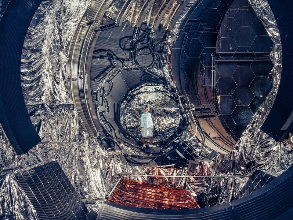
ESA. ESA, CC BY-SA 3.0 IGO [6].
The Large Space Simulator is Europe’s largest vacuum chamber, a 15 m by 10 m cylinder holding 2300 m3, with nitrogen-cooled shrouds down to about 100 K, a 6 m collimated solar beam adjustable from 70 to 2600 W/m2, and a motion system that turns a 5000 kg spacecraft under that beam to within 0.3 degrees [1][2]. It runs two to three tests a year [4].
Test Centre, not robotics laboratories: the chamber belongs to the ESTEC Test Centre, a 6000 square meter cleanroom complex operated under contract by European Test Services on ESA’s behalf [1][3][6]. ESTEC’s robotics rigs, the Mars Yard, the ORBIT flat floor and the Dusty Thermal Vacuum Chamber, are a different organization, the Automation and Robotics Laboratories under the Directorate of Technology, Engineering and Quality, with a different operator and a different access route [5].
Laboratory data
Section titled “Laboratory data”| Parameter | Value |
|---|---|
| Operator | ESA ESTEC Test Centre, operated by European Test Services on ESA’s behalf [1][3] |
| Location | ESTEC, Noordwijk, the Netherlands, in a dedicated building on the site [3] |
| Commissioned | First operational in 1986 [2]. Digital twin operator trainer added 2025 [4] |
| Type | Solar simulation thermal vacuum chamber with a spacecraft motion system [1][2] |
| Floor area | Not published as a floor area. Facility volume 2300 m3 |
| Capabilities | Main chamber, motion system, the rest |
| Simulant or terrain | Not applicable. No soil bin, no simulant |
| Instrumentation | Infrared thermography; photogrammetry; real-time facility data handling system |
| Ground truth | Non-contact: thermography for surface temperature, photogrammetry for deformation |
| Fidelity limits | 6 m beam in a 10 m chamber; collimation 1.9 degrees; shrouds bottom out near 100 K [1] |
| Access | ESA projects and outside organizations; route is the Test Centre Manager or ETS [2][3] |
| Cited by | None |
Throughput is the real access constraint. The facility’s own staff give the number and the reason: “we perform only about 2-3 tests per year, which offers very few occasions for a trainee to shadow and learn from an experienced operator”, and “the facility is very complex, and it takes many years for people to learn how to operate it” [4]. Individual thermal tests run for weeks at a time [2]. No lead time and no price is published. Hardware moves directly between Test Centre facilities without reconfiguration, which is the complex’s stated argument for handling time [2][3].
Capabilities
Section titled “Capabilities”Main chamber and solar beam
Section titled “Main chamber and solar beam”The facility is two chambers. The main one is a vertical cylinder 15 m high and 10 m across; the auxiliary one is horizontal and holds the collimating lens on a rigid support, so the solar beam is formed outside the volume the article occupies and enters it horizontally [1][2]. Total facility volume is 2300 m3.
| Parameter | Value |
|---|---|
| Working volume | Main chamber 15 m high by 10 m across; 2300 m3 total facility volume [1][2] |
| Test article limits | 5000 kg on the motion system including adaptor; 7000 kg static at zero tilt |
| Vacuum | Typical 5 x 10^-6 mbar, about 3.8 x 10^-6 torr; lowest achieved 3 x 10^-7 mbar |
| Temperature | Below 100 K in LN2 mode at 170 kW; 150 to 350 K in GN2 mode at 10 kW |
| Illumination | Solar beam 6 m diameter, 70 to 2600 W/m2, collimation angle 1.9 degrees |
| Gravity offload | Not applicable |
| Instrumentation | Infrared thermography and photogrammetry, both non-contact |
Article handling drives the architecture. The top flange is removable and forms a lid, so a tall spacecraft can be lowered in; a 5 m door at lower test floor level admits articles horizontally, with a man-sized door set inside it for access during a campaign; and the specimen support platform is mechanically decoupled from both the chamber and the building so that facility and building vibration do not reach the article, which is what makes dynamic tests, optical calibration and heat pipe operation possible during heat balance phases [1][2].
The solar beam is built from 19 xenon lamp modules, of which 12 at a nominal 20 kW are enough for one solar constant taken as 1380 W/m2 [1][2]. Running all 19 exceeds 2700 W/m2, and 32 kW lamps can be fitted [1][2]. The published range of 70 to 2600 W/m2 in the 6 m beam therefore spans roughly 0.05 to 1.9 solar constants, and the ten solar constant case exists only in a non-standard 2.7 m beam at a 9.8 degree full cone angle. Beam stability is plus or minus 0.5 percent at one solar constant, in-plane uniformity plus or minus 4 percent and in-volume uniformity plus or minus 6 percent [1][2].
Shrouds are stainless steel in both chambers, fed with liquid or gaseous nitrogen and controlled independently per chamber, at a surface emissivity of 0.90; the motion simulator carries its own thermally controlled shrouds [1][2]. No ramp rate and no shroud uniformity figure is published.
Pumping is by the oil-free central pumping system plus a dedicated high vacuum system of turbomolecular pumps and two closed-cycle refrigerator cryopumps, with one liquid helium cryopump available in the auxiliary chamber. Contamination control is designed into the sequence: two independent cryopanels are started early in evacuation and reconditioned only at venting, so condensable species are captured on them rather than on the article or the optics. Venting is staged, nitrogen gas to 100 mbar and then clean air to atmosphere, over a total time the user can set anywhere from 4 to 24 hours [1][2]. No pumpdown time is published [1][2].
Motion system
Section titled “Motion system”Solar elevation is a motion problem rather than an optical one. The beam is fixed and horizontal, and the article is turned into it by a gimbal stand or a yoke [1][2].
| Parameter | Value |
|---|---|
| Test article limits | 5000 kg with adaptor; 8000 kg m2 in fast spin, 55,000 kg m2 in slow spin [1][2] |
| Illumination | Solar elevation set by moving the article, not the beam |
| Slope | Article attitude to plus or minus 0.3 degrees; leveling table to 0.01 degrees |
Rotation is unlimited in the spin box and 270 degrees on the turntable and the tilting joint, at 0.25 to 2160 degrees per minute in the spin box and 0.25 to 10 degrees per minute on turntable and tilt, with plus or minus 0.3 degrees of position accuracy [1][2]. A leveling table on the yoke or gimbal controls satellite orientation to 0.01 degrees [1][2]. An orbital attitude profile is reproduced by turning the article, so the mass and moment of inertia limits are motion system limits rather than structural ones [1][2].
The rest of the complex
Section titled “The rest of the complex”The Large Space Simulator is one facility inside the complex. The Test Centre inventory covers the environments the robotics laboratories do not: 80 kN, 320 kN and 640 kN shakers plus the six degree of freedom HYDRA hydraulic shaker, the Large European Acoustic Facility, a shock bench, a microvibration characterization facility, mass property and dynamic balancing benches, the Phenix and VTC 1.5 thermal vacuum chambers alongside the Large Space Simulator, and the Maxwell EMC and AC magnetic facilities [6]. Dimensions, base pressures and capacities for those other chambers are not published, so none is tabulated here.
Instrumentation
Section titled “Instrumentation”Facility instrumentation is deliberately non-contact, because the article is inside a vacuum under a solar beam and thermocouple wiring is both a heat leak and a contamination source. Infrared thermography maps the temperature pattern across the article’s surfaces, and photogrammetry, listed as videogrammetry among the facility’s standard measurements, measures deformation to precision as materials expand and contract through a cycle [1][2].
Everything the facility itself does is recorded. The facility data handling system logs all facility parameters in real time, with a dedicated computer for analysis and fault finding, which is what allows a thermal balance test lasting weeks to be reconstructed afterward.
Article-side instrumentation passes through the chamber’s flanges and portholes, of which the operators state there are numerous, provided for instrumentation and observation and for spacecraft lines.
What it does not reproduce
Section titled “What it does not reproduce”Uniform illumination of anything wider than 6 m. The beam is 6 m across inside a 10 m chamber [1]. A large deployed array is illuminated in part, or in a smaller beam at a wider cone angle.
A point source. The collimation angle is 1.9 degrees [1], against the Sun’s apparent diameter of about half a degree from Earth and less from Mars. Shadow edges on the article are correspondingly soft, which matters for any test whose result depends on a terminator crossing a sensor or a radiator.
Flat illumination. In-plane uniformity is plus or minus 4 percent and in-volume uniformity plus or minus 6 percent at one solar constant, with beam stability of plus or minus 0.5 percent [1]. Those are the numbers a thermal balance test’s boundary condition carries.
High flux and good collimation at the same time. One to ten solar constants is available only in the 2.7 m beam at a 9.8 degree full cone angle [1]. An inner-solar-system flux case is therefore tested on a smaller article under a much less collimated beam.
Deep space. The shrouds reach below 100 K in liquid nitrogen mode and 150 to 350 K in gaseous nitrogen mode, at emissivity 0.90 [1]. A radiator whose design point is a 4 K sink sees about 100 K here.
Throughput. Two to three tests a year, for the reasons the operators give above [4]. This is why the digital twin was built.
Regolith, dust, gravity or terrain. None of these is provided [1][2]. The LSS is a spacecraft-level thermal and solar facility; the regolith work at ESTEC is done in the Dusty Thermal Vacuum Chamber of the Automation and Robotics Laboratories, whose bed is 0.5 x 0.5 x 0.2 m [5].
Comparable facilities
Section titled “Comparable facilities”The Large Space Simulator is not the largest thermal vacuum chamber built for spacecraft testing, nor the oldest active solar simulator; other national programs converged independently on the same combination of a large chamber, a collimated beam and a shared campus of mechanical and electromagnetic test stands.
NASA’s Space Power Facility at Plum Brook Station holds the largest thermal vacuum chamber in this comparison: 30.5 m in diameter and 37.2 m tall, a 22,653 m3 volume reaching below 2e-6 torr within eight hours, with shrouds from -150 to +60 C [7]. Between 2007 and 2011 the facility was augmented with a 34,000 kg, three-axis base shake table running 5 to 150 Hz, built around sixteen servohydraulic actuators once the required table mass ruled out electrodynamic shakers, a 2860 m3 reverberant acoustic chamber reaching 163 dB overall sound pressure level, and reverberant electromagnetic testing from 100 MHz to 40 GHz inside the same chamber shell, so that a full launch vehicle payload could complete thermal-vacuum, vibration, acoustic and EMI qualification in one building without teardown and transport between sites [7]. The Test Centre complex around the LSS follows the same logic at a smaller scale: hardware moves directly between the Large Space Simulator and the site’s shakers, acoustic facility and EMC chambers without reconfiguration [2][6].
JPL’s 25-ft Space Simulator is the LSS’s closest antecedent in solar simulation, and by a wide margin its senior: it was already in continuous use for Ranger, Mariner and Surveyor testing through 1963 and 1964 [8], two decades before the LSS existed, and it was still being booked for Mars 2020 instrument hardware in 2016 [12]. The chamber is a 27-ft diameter, 85-ft tall cylinder topped by a solar dome that brings its overall height to 80 ft, with simulated sunlight formed outside the main volume and folded in through a collimating mirror, the same architecture the LSS uses with its own auxiliary chamber and lens [8][12]. Its operators’ own two-year operating record names solar simulation as the facility’s largest single source of trouble, ahead of contamination, cryogenic leaks and staffing [8]. Their measured beam held to within about 3 percent over a selected 4-ft window of a roughly 7-ft hexagonal beam, at a nominal 184 W/ft2, but fell to roughly half that value outside the window, and diverged plus or minus 5.3 degrees against the real Sun’s 0.267 degrees, a collimation an order of magnitude worse than the LSS’s stated 1.9 degrees [8]. A 1964 spectral survey of the same beam, run by Eppley Laboratory with filter radiometers and two monochromators, found bands roughly 2.4 times too strong relative to the Johnson solar spectrum near 250 to 300 nm and other bands at about a third of solar intensity near 600 to 800 nm, a mismatch no equivalent published survey gives for the LSS beam [9]. The JPL mirror itself needs periodic recoating to hold its reflectivity: a 1994 in-chamber aluminizing campaign, using the chamber as its own vacuum vessel, targeted 89 to 90 percent reflectivity and measured 88.8 to 91 percent depending on witness sample and mirror location [11]. By 2016 the facility’s automation had aged enough that a Mars 2020 test campaign was run by hand through Hand/Off/Auto switches while the control system was mid-replacement, an 81-step manual procedure completed over 38 runs [12]. Between them, Plum Brook’s mass and JPL’s beam-testing history bound the LSS’s own numbers: bigger elsewhere, older elsewhere, but not both in the same chamber [7][12].
The oldest chambers in this set predate the LSS by two decades and were not built for robotic spacecraft at all. Houston’s Chambers A and B at the Space Environment Simulation Laboratory were built for Apollo and Gemini crewed qualification, and their own history records the same throughput pressure the LSS operators describe for themselves: the Apollo 204 fire delayed Chamber A’s test schedule while the crewed qualification program kept both chambers booked end to end [10]. A large solar-thermal-vacuum chamber whose binding constraint is schedule access rather than chamber physics is not new to the LSS; it is the condition every facility in this class has reported since the 1960s [8][10].
Campaigns run there
Section titled “Campaigns run there”The operators name Envisat, XMM, ERA, Herschel and the Automated Transfer Vehicle as LSS thermal and mechanical test articles, and BepiColombo’s Mercury Magnetospheric Orbiter is the illustrated test case [1][2]. At Test Centre level the complex has handled the 20 tonne ATV, Envisat, 22 Galileo Full Operational Capability satellites and the multi-module BepiColombo stack [6]. No campaign report gives measured conditions or findings for any of these; they are named on operator pages rather than written up in literature reachable from here.
The one recent development with a published account is the operator training simulator. A digital twin of the facility, built in EcosimPro by Empresarios Agrupados over almost two years, now runs on the real control room monitors so that operators can be trained without consuming one of the two or three annual test slots [4].
Thermal vacuum practice on robotic hardware
Section titled “Thermal vacuum practice on robotic hardware”The Large Space Simulator is one of three families of chamber that robotic flight hardware passes through. Spacecraft-scale solar simulators such as the LSS test whole vehicles under a collimated beam. Instrument- and subsystem-scale chambers carry the cold-soak and balance work for single assemblies. Soil and dust rigs add terrain but not a solar beam. The LSS covers the first only, and the robotics work that does reach a chamber of its class has mostly gone to JPL’s.
Spacecraft-scale solar simulators. JPL’s 25-ft Space Simulator is 25.9 m high and 8.2 m in diameter, with a usable volume of 6.1 m by 7.6 m under the solar beam and about 21.3 m of height for non-solar testing, pumped by ten 45,000 L/s cryopumps [14]. Its smaller sibling, the 10-ft Space Simulator, is 11.3 m between flanges and 3.96 m in inside diameter, 2.9 m usable with shrouds installed, with shrouds at -185 C and a base pressure below 5e-6 torr [13]. Johnson Space Center’s Chamber B is 7.6 m by 7.9 m with a 34,000 kg floor load limit, a 90 K shroud, a stated 8 hour pumpdown and human rating [16]. All three figures are stated capabilities, not measurements [13][14][16]. The 25-ft chamber’s original 1961 relay logic was replaced by programmable logic controllers between 1991 and 1994, and the paper describing the change records the operator displays as not yet built [15]. The 10-ft chamber was converted for twelve months into an ion engine test chamber for the Prometheus mission and converted back, which shows that these volumes are shared among programs rather than dedicated to one [27].
What has flown through such chambers. Ingenuity’s flight model went through the 25-ft chamber for a 40 C bakeout, thermal balance in vacuum and at Mars pressure with nitrogen backfill, a -90 C cold cycle and cold functional tests at a -50 C shroud; the earlier engineering model test forced design changes [17]. Mars rotorcraft aerodynamic campaigns used the same chamber backfilled with controlled carbon dioxide at Mars densities [29]. The Mars 2020 system thermal vacuum test ran six days in May 2019 with a surrogate rover chassis and a radioisotope generator qualification unit standing in for flight hardware, and its authors state that the chamber could not produce worst-case environments for all components [21]. The Mars Science Laboratory cruise solar thermal vacuum test of January 2009 is documented mainly as a safety and readiness exercise, with rehearsed failure scenarios injected over the comm net and almost no thermal data [18]. The Mars 2020 program’s margin policy for thermal levels, cycles and ramp rates is tabulated by its requirements engineers [19], and the Mars Exploration Rover campaign at JPL’s Environmental Test Laboratory between 2001 and 2003 is described without findings [20]. VIPER passed vibration and 138 dB acoustic testing in 2024, with thermal vacuum still scheduled when that record was written [31]; its loop heat pipe was tested separately in an MSFC chamber at about -170 C shroud and 1 torr [28].
Subsystem and instrument chambers. The Europa Clipper MISE spectrometer used a 1.2 m by 3 m horizontal chamber with a five-zone shroud for three thermal vacuum tests between October 2021 and June 2023, the last lasting 35 days [22]. SHERLOC’s deep ultraviolet laser required purpose-built ground support equipment and test facilities and the account reports almost no measured data [30]. A 5 m AstroMesh deployable reflector was measured by photogrammetry through a 36-hour solar thermal vacuum run in the 25-ft chamber, reaching 0.025 mm RMS shape resolution over the aperture [23]. That is the same deformation measurement the LSS lists among its standard tests [2].
In-chamber robots. The Satellite Test Assistant Robot moved video and infrared cameras inside the 25-ft chamber; its infrared camera matched thermocouples to 0.5 C on low-emissivity samples and showed blocked shroud tubes and a door shroud lag in a December 1994 proof test [24], and it was proof tested from 60 to 190 C at 1e-6 torr [25]. Both are single-chamber developer reports. No equivalent in-chamber robot is documented for the LSS.
Dust, soil and terrain. Terrain-dependent robotics work is done elsewhere. NASA Glenn’s planetary exploration rigs include soil tanks, a single-wheel dynamometer and an excavation lab, described by capability and not by measurement [32]. ESTEC’s own robotics facility for orbital work is a flat air-bearing floor and a robot arm on a 33 m track, and the paper describing it reports no measurements [26]. The Dusty Thermal Vacuum Chamber is the ESTEC route for regolith under thermal vacuum [5]. NASA’s 2025 consolidation of planetary mobility test practice records that no known facility reproduces the inertial and dynamic effects of a vehicle specified to 15 km/h, and that VIPER wheel endurance was verified on a 6 m linear track run to twice the 20 km requirement [33].
What is not established
Section titled “What is not established”Every LSS figure comes from operator capability pages, which state envelopes without measurements, uncertainty or calibration basis, and are undated and subject to change [1][2][6]. Whether the maxima can be held together, for example full solar intensity with full mass on the motion system, is not stated [1]. The Test Centre page lists the thermal vacuum chambers Phenix and VTC 1.5 and the shakers without dimensions, pressures or sound pressure levels [6], and the About page carries no envelope at all [3]. No spectral survey of the LSS beam is held, although one exists for the JPL beam [9]. No campaign report with measured conditions is held for any article tested in the LSS [1][2][6]. No ESTEC-tested planetary rover or manipulator is documented in the corpus; robotic hardware examples above are JPL and NASA campaigns [17][21][29]. The digital twin is reported without validation figures, accuracy or a list of modeled subsystems [4]. The ESTEC robotics laboratory index names the Dusty Thermal Vacuum Chamber without a size, pressure or dust loading [5].
References
- (2026). ESA: Large Space Simulator. technology.esa.int/page/large-space-simulator
BibTeX
@misc{esalss, title = {ESA: Large Space Simulator}, organization = {technology.esa.int}, year = {2026}, url = {https://technology.esa.int/page/large-space-simulator} } - (2026). ESA: Large Space Simulator (LSS). esa.int/Enabling_Support/Space_Engineering_Technology/Test_centre/Lar...
BibTeX
@misc{esalssoverview, title = {ESA: Large Space Simulator (LSS)}, organization = {esa.int}, year = {2026}, url = {https://www.esa.int/Enabling_Support/Space_Engineering_Technology/Test_centre/Large_Space_Simulator_LSS} } - (2026). About ESTEC Test Centre. esa.int/Enabling_Support/Space_Engineering_Technology/Test_centre/Abo...
BibTeX
@misc{esatestcentreabout, title = {About {ESTEC} Test Centre}, organization = {European Space Agency}, year = {2026}, url = {https://www.esa.int/Enabling_Support/Space_Engineering_Technology/Test_centre/About_ESTEC_Test_Centre} } - (2025). Large Space Simulator gets a digital twin. esa.int/Enabling_Support/Space_Engineering_Technology/Large_Space_Sim...
BibTeX
@misc{esalssdigitaltwin, title = {Large Space Simulator gets a digital twin}, organization = {European Space Agency}, year = {2025}, url = {https://www.esa.int/Enabling_Support/Space_Engineering_Technology/Large_Space_Simulator_gets_a_digital_twin} } - (2026). ESA Automation and Robotics Laboratories. technology.esa.int/lab/automation-and-robotics-laboratories
BibTeX
@misc{esaarlabs, title = {ESA Automation and Robotics Laboratories}, organization = {technology.esa.int}, year = {2026}, url = {https://technology.esa.int/lab/automation-and-robotics-laboratories} } - (2026). ESA: Test Centre. technology.esa.int/lab/test-centre
BibTeX
@misc{esatestcentre, title = {ESA: Test Centre}, organization = {technology.esa.int}, year = {2026}, url = {https://technology.esa.int/lab/test-centre} } - Motil, S. M., Ludwiczak, D. R., Carek, G. A., Sorge, R. N., Free, J. M. and Cikanek, H. A. (2011). Capabilities, Design, Construction and Commissioning of New Vibration, Acoustic, and Electromagnetic Capabilities Added to the World's Largest Thermal Vacuum Chamber at NASA's Space Power Facility
. International Astronautical Congress, IAC-11-C2.1.7. Source
BibTeX
@inproceedings{motil2011capabilities, title = {Capabilities, Design, Construction and Commissioning of New Vibration, Acoustic, and Electromagnetic Capabilities Added to the World's Largest Thermal Vacuum Chamber at {NASA}'s Space Power Facility}, author = {Motil, Susan M. and Ludwiczak, Damian R. and Carek, Gerald A. and Sorge, Richard N. and Free, James M. and Cikanek, Harry A.}, booktitle = {International Astronautical Congress, IAC-11-C2.1.7}, address = {Cape Town, South Africa}, year = {2011}, url = {https://ntrs.nasa.gov/citations/20110016431}, abstract = {NASA s human space exploration plans developed under the Exploration System Architecture Studies in 2005 included a Crew Exploration Vehicle launched on an Ares I launch vehicle. The mass of the Crew Exploration Vehicle and trajectory of the Ares I coupled with the need to be able to abort across a large percentage of the trajectory generated unprecedented testing requirements. A future lunar lander added to projected test requirements. In 2006, the basic test plan for Orion was developed. It included several types of environment tests typical of spacecraft development programs. These included thermal-vacuum, electromagnetic interference, mechanical vibration, and acoustic tests. Because of the size of the vehicle and unprecedented acoustics, NASA conducted an extensive assessment of options for testing, and as result, chose to augment the Space Power Facility at NASA Plum Brook Station, of the John H. Glenn Research Center to provide the needed test capabilities. The augmentation included designing and building the World s highest mass capable vibration table, the highest power large acoustic chamber, and adaptation of the existing World s largest thermal vacuum chamber as a reverberant electromagnetic interference test chamber. These augmentations were accomplished from 2007 through early 2011. Acceptance testing began in Spring 2011 and will be completed in the Fall of 2011. This paper provides an overview of the capabilities, design, construction and acceptance of this extraordinary facility.} } - Goranson, G. G. (1966). Comments on the Operation of the JPL 25-ft Space Simulator
. Jet Propulsion Laboratory, California Institute of Technology, Technical Report 32-885. Source
BibTeX
@techreport{goranson1966comments, title = {Comments on the Operation of the {JPL} 25-ft Space Simulator}, author = {Goranson, George G.}, number = {Technical Report 32-885}, institution = {Jet Propulsion Laboratory, California Institute of Technology}, year = {1966}, url = {https://ntrs.nasa.gov/citations/19660010341}, abstract = {Operational problems of large space simulator and importance of combined solar and space simulation} } - Hickey, J. R. (1965). Evaluation of the Simulated Solar Spectrum in the JPL 25-ft Space Simulator
. Jet Propulsion Laboratory, California Institute of Technology, Technical Report 32-749. Source
BibTeX
@techreport{hickey1965evaluation, title = {Evaluation of the Simulated Solar Spectrum in the {JPL} 25-ft Space Simulator}, author = {Hickey, J. R.}, number = {Technical Report 32-749}, institution = {Jet Propulsion Laboratory, California Institute of Technology}, year = {1965}, url = {https://ntrs.nasa.gov/citations/19650025700}, abstract = {Simulation of solar spectrum in space simulator} } - Walters, L. C. (2003). To Create Space on Earth: The Space Environment Simulation Laboratory and Project Apollo
. NASA, NASA/CR-2003-208933. Source
BibTeX
@techreport{walters2003create, title = {To Create Space on Earth: The {Space Environment Simulation Laboratory} and {Project Apollo}}, author = {Walters, Lori C.}, number = {NASA/CR-2003-208933}, institution = {NASA}, year = {2003}, url = {https://ntrs.nasa.gov/citations/20030019356}, abstract = {Few undertakings in the history of humanity can compare to the great technological achievement known as Project Apollo. Among those who witnessed Armstrong#s flickering television image were thousands of people who had directly contributed to this historic moment. Amongst those in this vast anonymous cadre were the personnel of the Space Environment Simulation Laboratory (SESL) at the Manned Spacecraft Center (MSC) in Houston, Texas. SESL houses two large thermal-vacuum chambers with solar simulation capabilities. At a time when NASA engineers had a limited understanding of the effects of extremes of space on hardware and crews, SESL was designed to literally create the conditions of space on Earth. With interior dimensions of 90 feet in height and a 55-foot diameter, Chamber A dwarfed the Apollo command/service module (CSM) it was constructed to test. The chamber#s vacuum pumping capacity of 1 x 10(exp -6) torr can simulate an altitude greater than 130 miles above the Earth. A "lunar plane" capable of rotating a 150,000-pound test vehicle 180 deg replicates the revolution of a craft in space. To reproduce the temperature extremes of space, interior chamber walls cool to -280F as two banks of carbon arc modules simulate the unfiltered solar light/heat of the Sun. With capabilities similar to that of Chamber A, early Chamber B tests included the Gemini modular maneuvering unit, Apollo EVA mobility unit and the lunar module. Since Gemini astronaut Charles Bassett first ventured into the chamber in 1966, Chamber B has assisted astronauts in testing hardware and preparing them for work in the harsh extremes of space.} } - Noller, E. W. (1994). The Realuminizing of the 7-Meter-Diameter Solar Simulator Collimating Mirror
. Space Simulation Conference. Source
BibTeX
@inproceedings{noller1994realuminizing, title = {The Realuminizing of the 7-Meter-Diameter Solar Simulator Collimating Mirror}, author = {Noller, E. W.}, booktitle = {Space Simulation Conference}, institution = {Jet Propulsion Laboratory, California Institute of Technology}, year = {1994}, url = {https://ntrs.nasa.gov/citations/19950007668}, abstract = {This paper describes the modification of a three-electron-beam (EB) gun system for vacuum depositing a highly reflective aluminum coating on a 7.01-m (23-ft) -diam nickel-plated aluminum collimating mirror. The mirror is part of the JPL 7.62-m space simulator that was recently modernized with a new high vacuum pumping system, solar lamp power supplies, solar optic lens system, and refurbished collimating mirror. The 7.01-m 12,700-kg (14-ton) spherical collimating mirror was removed from this facility for replating with 381 micron (0.015 in.) of electroless nickel and polished to a specular finish for realuminizing. The space chamber served as the vacuum coating vessel for the realuminizing coating process. The mirror is the primary reflector for the solar simulation system and the aluminized reflective surface is its most critical performance element. The uniformity of thickness and high reflectivity of the coating in visible and near-ultraviolet (UV) light governs the accuracy of the beam for solar testing. The uniformity of the thin-film thickness also controls the durability of the mirror over time. The mirror was polished to a 64-percent reflectivity with a uniformity of 1.5 percent. The performance goal for the aluminizing was 89 percent with +/- 0.5-percent variation over the mirror.} } - Ovcharenko, A. (2016). Environmental Testing of Flight Hardware in the 25 ft Space Simulator at JPL
. Jet Propulsion Laboratory, California Institute of Technology. Source
BibTeX
@techreport{ovcharenko2016environmental, title = {Environmental Testing of Flight Hardware in the 25 ft Space Simulator at {JPL}}, author = {Ovcharenko, Alexander}, institution = {Jet Propulsion Laboratory, California Institute of Technology}, year = {2016}, url = {https://www.jpl.nasa.gov/who-we-are/facilities/} } - Jet Propulsion Laboratory. (2001). 10-ft Space Simulator Facility Description, Building 248
. Jet Propulsion Laboratory, California Institute of Technology. Source
BibTeX
@techreport{brown200110ft, title = {10-ft Space Simulator Facility Description, Building 248}, author = {{Jet Propulsion Laboratory}}, institution = {Jet Propulsion Laboratory, California Institute of Technology}, year = {2001}, url = {https://www.jpl.nasa.gov/who-we-are/facilities/} } - Jet Propulsion Laboratory. (2001). 25-FT Space Simulator Facility Description, Building 150
. Jet Propulsion Laboratory, California Institute of Technology. Source
BibTeX
@techreport{jpl2001space, title = {25-FT Space Simulator Facility Description, Building 150}, author = {{Jet Propulsion Laboratory}}, institution = {Jet Propulsion Laboratory, California Institute of Technology}, year = {2001}, url = {https://dataverse.jpl.nasa.gov/dataset.xhtml?persistentId=hdl:2014/36839} } - Johnson, K. R. (1994). The New Distributed Computerized Control System of JPL's 25-ft Space Simulator
. AIAA Aerospace Ground Testing Conference, AIAA 94-2676. Source
BibTeX
@inproceedings{johnson1994new, title = {The New Distributed Computerized Control System of {JPL}'s 25-ft Space Simulator}, author = {Johnson, Kenneth R.}, booktitle = {AIAA Aerospace Ground Testing Conference}, number = {AIAA 94-2676}, year = {1994}, doi = {10.2514/6.1994-2676}, abstract = {A project to refurbish the JPL 25-ft space simulator facilities which began in May 1991 will be complete by June 1994.} } - Montz, M. and Trevino, L. (2012). Chamber B Thermal/Vacuum Chamber: User Test Planning Guide
. NASA Johnson Space Center, 20120003246. Source
BibTeX
@techreport{montz2012chamber, title = {{Chamber B} Thermal/Vacuum Chamber: User Test Planning Guide}, author = {Montz, Michael and Trevino, Louis}, number = {20120003246}, institution = {NASA Johnson Space Center}, year = {2012}, url = {https://ntrs.nasa.gov/citations/20120003246}, abstract = {Test process, milestones and inputs are unknowns to first-time users of Chamber B. The User Test Planning Guide aids in establishing expectations for both NASA and non-NASA facility customers. The potential audience for this guide includes both internal and commercial spaceflight hardware/software developers. It is intended to assist their test engineering personnel in test planning and execution. Material covered includes a roadmap of the test process, roles and responsibilities of facility and user, major milestones, facility capabilities, and inputs required by the facility. Samples of deliverables, test article interfaces, and inputs necessary to define test scope, cost, and schedule are included as an appendix to the guide.} } - Cappucci, S. and Pauken, M. (2020). Thermal system and environmental testing of the Mars Helicopter
. JPL Open Repository. Source
BibTeX
@inproceedings{cappucci2020thermal, title = {Thermal system and environmental testing of the Mars Helicopter}, author = {Cappucci, Stefano and Pauken, Michael}, publisher = {JPL Open Repository}, year = {2020}, url = {https://dataverse.jpl.nasa.gov/dataset.xhtml?persistentId=hdl:2014/53049} } - Evans, J. P. (2010). Managing the Mars Science Laboratory thermal vacuum test for safety and success
. IEEE Aerospace Conference. Source
BibTeX
@inproceedings{evans2010managing, title = {Managing the Mars Science Laboratory thermal vacuum test for safety and success}, author = {Evans, Jordan P.}, booktitle = {IEEE Aerospace Conference}, pages = {1-9}, publisher = {IEEE}, year = {2010}, doi = {10.1109/aero.2010.5446861}, abstract = {The Mars Science Laboratory is a NASA/JPL mission to send the next generation of rover to Mars. Originally slated for launch in 2009, development problems led to a delay in the project until the next launch opportunity in 2011. Amidst the delay process, the Launch/Cruise Solar Thermal Vacuum Test was undertaken as risk reduction for the project. With varying maturity and capabilities of the flight and ground systems, undertaking the test in a safe manner presented many challenges. This paper describes the technical and management challenges and the actions undertaken that led to the ultimate safe and successful execution of the test.} } - Dodge, R., Kartolov, B. and Seal, G. L. (2020). Highlights of the Mars 2020 Environmental Test Program
. The Planetary Science Journal. Source
BibTeX
@article{dodge2020highlights, title = {Highlights of the Mars 2020 Environmental Test Program}, author = {Dodge, Randy and Kartolov, Boyan and Seal, Gabriella L}, journal = {The Planetary Science Journal}, publisher = {JPL Open Repository}, year = {2020}, url = {https://dataverse.jpl.nasa.gov/dataset.xhtml?persistentId=hdl:2014/52312} } - Fisher, T. C. and Van Velzer, P. L. (2004). Environmental test program for the Mars Exploration Rover Project
. International Symposium on Environmental Testing for Space Programs. Source
BibTeX
@inproceedings{fisher2004environmental, title = {Environmental test program for the Mars Exploration Rover Project}, author = {Fisher, Terry C. and Van Velzer, Paul L.}, booktitle = {International Symposium on Environmental Testing for Space Programs}, publisher = {JPL Open Repository}, year = {2004}, url = {https://dataverse.jpl.nasa.gov/dataset.xhtml?persistentId=hdl:2014/38001} } - Miller, J. R., Singh, K., Reilly, S., Novak, K. and Lyra, J. (2022). Mars 2020 System Thermal Vacuum (STV) Test Implementation and Results
. Root. Source
BibTeX
@inproceedings{miller2022mars, title = {Mars 2020 System Thermal Vacuum (STV) Test Implementation and Results}, author = {Miller, Jennifer R. and Singh, Kaustabh and Reilly, Sean and Novak, Keith and Lyra, Jackie}, journal = {Root}, publisher = {JPL Open Repository}, year = {2022}, doi = {10.48577/jpl.uhmv4z}, abstract = {No abstract available.} } - Rodriguez, J. I., McKinley, I. M., Hummel, C., Mueller, B., Burgon, R., Ostler, A. and Bingham, C. (2025). Thermal Vacuum Testing of the Mapping Imaging Spectrometer for Europa Instrument on Clipper
. International Conference on Environmental Systems. Source
BibTeX
@inproceedings{rodriguez2025thermal, title = {Thermal Vacuum Testing of the Mapping Imaging Spectrometer for Europa Instrument on Clipper}, author = {Rodriguez, Jose I. and McKinley, Ian M. and Hummel, Chris and Mueller, Bryant and Burgon, Rex and Ostler, Andrew and Bingham, Curtis}, booktitle = {International Conference on Environmental Systems}, publisher = {JPL Open Repository}, year = {2025}, doi = {10.48577/jpl.xmu309} } - Stegman, M. D. (2009). Solar thermal vacuum test of deployable astromesh reflector
. Aerospace. Source
BibTeX
@inproceedings{stegman2009solar, title = {Solar thermal vacuum test of deployable astromesh reflector}, author = {Stegman, Matthew D.}, booktitle = {Aerospace}, publisher = {JPL Open Repository}, year = {2009}, url = {https://dataverse.jpl.nasa.gov/dataset.xhtml?persistentId=hdl:2014/45191} } - McAffee, D., Long, M., Johnson, K. and Siebes, G. (1995). Performance of the Satellite Test Assistant Robot (STAR) in JPL's Space Simulation. dataverse.jpl.nasa.gov/dataset.xhtml
BibTeX
@misc{mcaffee1995performance, title = {Performance of the Satellite Test Assistant Robot (STAR) in JPL's Space Simulation}, author = {McAffee, Douglas and Long, Mark and Johnson, Ken and Siebes, Georg}, year = {1995}, url = {https://dataverse.jpl.nasa.gov/dataset.xhtml?persistentId=hdl:2014/29500} } - Johnson, K., Siebes, G. and McAffee, D. (1996). Utilization fo the Satellite Test Assistant Robot (STAR) for Visual and Thermal Analysis for Articles in the Thermal Vacuum Test Environment
. The Planetary Report. Source
BibTeX
@inproceedings{johnson1996utilization, title = {Utilization fo the Satellite Test Assistant Robot (STAR) for Visual and Thermal Analysis for Articles in the Thermal Vacuum Test Environment}, author = {Johnson, K. and Siebes, G. and McAffee, D.}, booktitle = {The Planetary Report}, publisher = {JPL Open Repository}, year = {1996}, url = {https://dataverse.jpl.nasa.gov/dataset.xhtml?persistentId=hdl:2014/23814} } - Zwick, M., Huertas, I., Gerdes, L. and Ortega, G. (2018). ORGL: ESA's Test Facility for Approach and Contact Operations in Orbital and Planetary Environments
. International Symposium on Artificial Intelligence, Robotics and Automation in Space. Source
BibTeX
@inproceedings{zwick2018orgl, title = {{ORGL}: {ESA}'s Test Facility for Approach and Contact Operations in Orbital and Planetary Environments}, author = {Zwick, Martin and Huertas, Irene and Gerdes, Levin and Ortega, Guillermo}, booktitle = {International Symposium on Artificial Intelligence, Robotics and Automation in Space}, organization = {European Space Agency}, address = {Madrid, Spain}, year = {2018}, url = {https://roboshare.esa.int/i-SAIRAS/isairas2018/} } - Van Velzer, P. (2006). Convert Ten Foot Environmental Test Chamber into an Ion Engine Test Chamber
. Space Simulation Conference. Source
BibTeX
@inproceedings{vanvelzer2006convert, title = {Convert Ten Foot Environmental Test Chamber into an Ion Engine Test Chamber}, author = {Van Velzer, Paul}, booktitle = {Space Simulation Conference}, organization = {Institute of Environmental Sciences and Technology}, address = {Annapolis, Maryland}, year = {2006}, url = {https://www.iest.org/Standards-RPs/Space-Simulation-Conference} } - Medici, E. F., Turk, J. C., Stewart, E. R., Page, T., Dobarco-Otero, J., Quintanilla, G., Slusser, T. B., Mittag, Z. W., Barragan, J. M., Alvarez-Hernandez, A., Bugby, D. C., Hughes, J., Smay, J. and Tarau, C. (2025). Thermal Vacuum Testing of a VIPER Loop Heat Pipe, 20250007125. ntrs.nasa.gov/citations/20250007125
BibTeX
@misc{medici2025thermal, title = {Thermal Vacuum Testing of a VIPER Loop Heat Pipe}, author = {Medici, Ezequiel F. and Turk, Jodi C. and Stewart, Elijah R. and Page, Tim and Dobarco-Otero, Jose and Quintanilla, Geronimo and Slusser, Thomas B. and Mittag, Zane W. and Barragan, Juan M. and Alvarez-Hernandez, Angel and Bugby, David C. and Hughes, Jimmy and Smay, Joshua and Tarau, Calin}, howpublished = {Presentation at the Thermal and Fluids Analysis Workshop}, number = {20250007125}, address = {San Jose, California}, year = {2025}, url = {https://ntrs.nasa.gov/citations/20250007125}, abstract = {NASA’s Volatiles Investigating Polar Exploration Rover (VIPER) was designed operate in the extreme thermal environment of the lunar south pole. The rover uses Loop Heat Pipes (LHP) as the primary device to transport heat from the Warm Electronic Box (WEB) to the radiators. An Engineering Design Unit (EDU) LHP has been tested under Thermal Vacuum (TVAC) environment to characterize its performance, assist on design of the flight hardware, provide thermal-power data for modeling correlation, and facilitate console operator training. The effect of gravity, 1g versus the lunar 1/6 of Earth gravity, thermal loads, sink temperatures, and heating choreography on the steady state LHP performance were some of the design parameters evaluated. Transient behaviors like LHP startup, and LHP shutdown, were also investigated. This technical presentation will summarize the instrumentation, the temperature and power measurements, and the observed LHP dynamics through the different TVAC test segments.} } - Schatzman, N. L., Koning, W. J. F., Russell, C. and Withrow-Maser, S. (2024). Performance Analysis and Data Processing for the Mars Sample Recovery Helicopter in the Jet Propulsion Laboratory 25-ft Space Simulator
. Vertical Flight Society Annual Forum and Technology Display. Source
BibTeX
@inproceedings{schatzman2024performance, title = {Performance Analysis and Data Processing for the Mars Sample Recovery Helicopter in the Jet Propulsion Laboratory 25-ft Space Simulator}, author = {Schatzman, Natasha L. and Koning, Witold J. F. and Russell, Carl and Withrow-Maser, Shannah}, booktitle = {Vertical Flight Society Annual Forum and Technology Display}, pages = {1-11}, institution = {NASA Ames Research Center}, year = {2024}, doi = {10.4050/f-0080-2024-1357}, abstract = {On April 19, 2021, Ingenuity became the first helicopter to fly on Mars at Jezero Crater, completing a total of 72 flights by the end of its mission. The success of Ingenuity resulted in various research efforts to further exploreMars via vertical flight, including two optimized Ingenuity-sized helicopters proposed to retrieve samples for the 2028 Mars Sample Return mission. To aid in the design process for the two proposed Sample Retrieval Helicopters, both heritage and optimized, increased diameter rotors were tested at the NASA Jet Propulsion Laboratory in the 25-ft Space Simulator. Three test campaigns were performed using the Ingenuity rotors and optimized Sample Retrieval Helicopter (SRH) rotors for several rotor speeds, densities, configurations, and collectives to identify performance limitations. These three test campaigns included the Ingenuity Engineering Design Model 1 (EDM-1) with and without a cruciform box, Transonic Rotor Test (TRT) rig, and SRH Dual Rotor Test (DRT). Experimental setup, test matrix, data processing, data quality, and performance results for EDM-1, TRT, and DRT campaigns are presented and discussed. Experimental results from the test campaigns will aid in future experimental methods and validation efforts for planetary rotorcraft exploration.} } - Hein, J., Beegle, L., Miller, E., Aldrich, D., Hochberg, E., Mok, F., Shelton, M., Simon, R., Vorperian, V., Bhartia, R., Reid, R., Hug, W. and Houck, A. (2022). Test Facilities for SHERLOC Laser Development
. IEEE Aerospace Conference. Source
BibTeX
@inproceedings{hein2022test, title = {Test Facilities for SHERLOC Laser Development}, author = {Hein, Jeffrey and Beegle, Luther and Miller, Ed and Aldrich, David and Hochberg, Eric and Mok, Fai and Shelton, Molly and Simon, Rufus and Vorperian, Vatche and Bhartia, Rohit and Reid, Ray and Hug, William and Houck, Andrew}, booktitle = {IEEE Aerospace Conference}, publisher = {JPL Open Repository}, year = {2022}, url = {https://dataverse.jpl.nasa.gov/dataset.xhtml?persistentId=hdl:2014/55979} } - Andrews, D. (2024). VIPER Rover: Flight Build and Environmental Test Status
. International Astronautical Congress, 20240002248. Source
BibTeX
@inproceedings{andrews2024viper, title = {VIPER Rover: Flight Build and Environmental Test Status}, author = {Andrews, Daniel}, booktitle = {International Astronautical Congress}, number = {20240002248}, pages = {76-82}, institution = {NASA}, year = {2024}, doi = {10.52202/078357-0013}, abstract = {The NASA Artemis Program plans to return humans to the Moon to stay. Extended human stays on the Moon will require substantial resources to sustain human presence, requiring continuous supplies delivered from the Earth. However, if some of the resources were indigenously available, Earth logistical requirements could be substantially reduced by “living off the land” with in-situ lunar resources. Local volatiles could be processed into propellants and human life-supporting needs, reducing risk of maintaining a permanent human presence on the Moon. LCROSS, LRO and other missions have confirmed the presence of lunar volatiles resources in polar regions, so the next step is to understand the physical distribution of those resources, as well as the scientific basis for how water got there, and why it is still there. The Volatiles Investigating Polar Exploration Resource (VIPER) is a surface mobility scientific platform, designed to spend ~100 days mapping and surveying four different Ice Stability Regions to understand the scientific nature and distribution of water and other volatiles. VIPER will also provide scientific mineralogical context of the lunar regolith, such as the presence of silicon and light metals in lunar regolith, providing a composite picture of resource availability and sustainment. This paper will discuss VIPER’s completion of the flight rover build, as well as current progress in environmental testing, preparedness for mission operations, and overall readying for launch integration with our CLPS partner. VIPER is managed within NASA’s Science Mission Directorate (SMD), utilizing the Commercial Lunar Payload Services (CLPS) lunar delivery model} } - NASA Glenn Research Center. (2025). Planetary Exploration Test Facilities. nasa.gov/centers-and-facilities/glenn/planetary-exploration-test-faci...
BibTeX
@misc{grc2025planetary, title = {Planetary Exploration Test Facilities}, author = {{NASA Glenn Research Center}}, organization = {nasa.gov}, year = {2025}, url = {https://www.nasa.gov/centers-and-facilities/glenn/planetary-exploration-test-facilities/} } - Creager, C., Breckenridge, J., Johnson, K., Oravec, H., Moreland, S., Sobey, A. and McBryan, E. (2025). Best Practices for the Testing of Planetary Roving Vehicle Mobility Systems and Tires
. NASA, 20250003470. Source
BibTeX
@techreport{creager2025best,
  title = {Best Practices for the Testing of Planetary Roving Vehicle Mobility Systems and Tires},
  author = {Creager, Colin and Breckenridge, John and Johnson, Kyle and Oravec, Heather and Moreland, Scott and Sobey, Alexander and McBryan, Emily},
  number = {20250003470},
  institution = {NASA},
  year = {2025},
  url = {https://ntrs.nasa.gov/citations/20250003470},
  abstract = {NASA has an extensive history of conducting mobility testing on planetary tires, rovers, and mobility subsystems.  This paper contains a summary of the best practices and lessons learned from past test approaches, as well as from relevant test methodologies external to NASA, with a focus on tires and mobility systems.  It is intended to be a resource for future planetary rover developments. This document, which will be released in two phases, serves two objectives:  1) compile the existing knowledge of mobility related testing within NASA; and 2) identify major gaps in mobility related test needs and suggest potential paths forward.  This first release of the document (early 2025) captures information based on the authors’ existing knowledge and an abbreviated literature review.  A more thorough version will be released in late 2025 and will include more information on test methods external to NASA, as well as additional lessons learned through further investigations.  The Lunar Terrain Vehicle (LTV) is used as case study to help identify major test needs; however, this document is intended to be applicable to a wide range of potential missions.  Though no current mobility standards exist for the testing of planetary tires and mobility subsystems, future motive is to utilize the information from this whitepaper to guide the development of NASA mobility test standards.}
}