Beagle 2 PAW and ARM
Program pages ESA: Beagle 2 lander
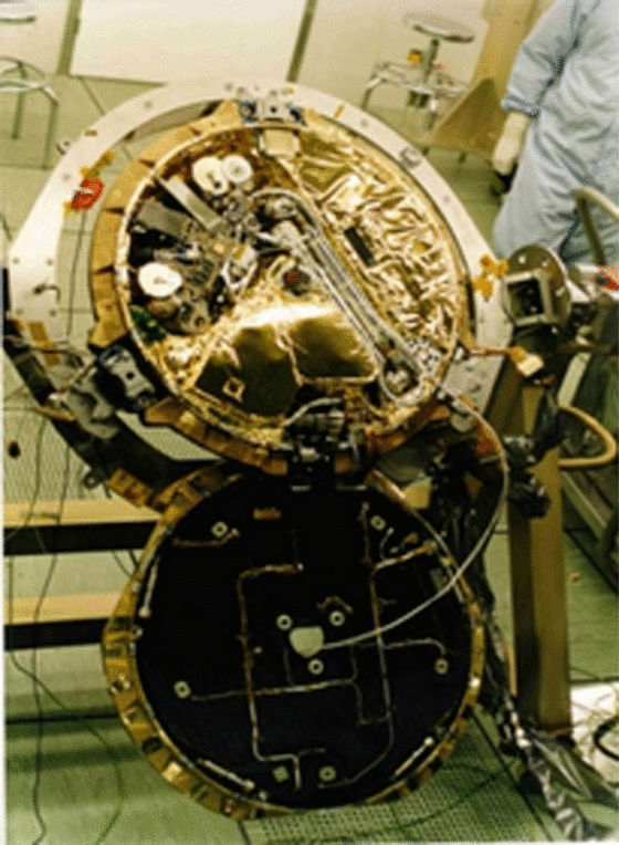 Source: Bridges et al. 2017, Royal Society Open Science, figure 4 [5]; CC BY 4.0.
The problem
Section titled “The problem”A Mars lander arm has to put instruments and sampling tools on rock and soil it has seen only in stereo images, with no human able to correct a placement in real time. A UHF relay pass gives a few contacts per sol, so every arm sequence is planned a sol ahead and executed blind [8]. Contact with an unseen surface cannot be rehearsed, so the arm either carries a force sensor or detects contact by another means and stops. The soil is not what orbital data suggest: Viking measured drift material at 1,200 kg/m3 with 0.7 to 3.0 kPa cohesion, and crusty or cloddy material behaves differently under a tool [13]. InSight later found a duricrust at the HP3 site with penetration resistance of 0.5 to 1.2 MPa and cohesion of 4 to 25 kPa [18].
Beagle 2 added a mass constraint: the lander was 33 kg on a 69 kg probe limit, and the program aimed at the highest ratio of payload to support systems flown to Mars, which meant an integrated design and minimal or zero redundancy [9]. ESA’s mission description makes the same point: the volume was set by the aeroshell, and no supplier makes boxes at that scale [14]. The consequence for the arm was an architecture in which the instruments sit on the wrist, so the arm exists to point a payload.
What has flown
Section titled “What has flown”Beagle 2 ARM and PAW (never exercised). The Anthropomorphic Robotic Manipulator has five degrees of freedom and 109 cm of reach [9]. It ends in the Position Adjustable Workbench, a fixed cluster of stereo cameras, microscope, X-ray spectrometer, Mossbauer spectrometer, rock corer grinder, wind sensor, torch, spoon and the launch tube for the PLUTO mole [9]. The lander reached Isidis Planitia on 25 December 2003 and never communicated [11]. HiRISE imaging identified it in 2014 and 2015, and the object is consistent with lid deployment and partial solar panel deployment, which would have left the UHF antenna covered [5]. The ARM, PAW and PLUTO were therefore never operated on Mars, and every number for them is an as-built or as-tested value [9].
Mars Surveyor 2001 and Phoenix arms. The Mars Surveyor 2001 lander arm was a 4 degree of freedom back-hoe design with graphite epoxy links, canceled before flight [1]. Its MVACS-class lineage produced the Phoenix arm and, refurbished, the InSight arm [2]. The Phoenix arm, flown in 2008, is a 2.4 m back-hoe with a scoop, dual blades and a rasp, built to acquire dry and icy soil for the deck instruments [3]. Over more than 150 sols it executed 53 dig sequences across 10 trenching areas and delivered 18 samples to instruments [4].
InSight Instrument Deployment Arm (2018 to 2022). The arm has 4 degrees of freedom and 1.8 m reach [15]. It placed the wind and thermal shield over the seismometer to within 1.5 cm of the intended position, the first robotic stacking of one instrument over another [15]. When the HP3 mole stalled, the arm took part in an anomaly recovery campaign that included pinning the mole with the scoop, which gained 5 cm of penetration, and pushing on the mole back cap [16]. Scoop pushes and indentation tests near the pit were reduced to soil cohesion of 3 to 14.5 kPa and friction angle of 30 to 34 degrees [17].
Perseverance arm (2021). The arm has 5 actuators over two titanium links and a redundant 6 degree of freedom force-torque sensor at the wrist [21]. Resolver angles on sol 11 agreed with pre-launch values within 5 mrad. The first surface contact came 2 mm early at about 30 N, and docking to the bit carousel, the first on another planet, succeeded on the first attempt [21]. Of the force-corrected dockings on Mars analyzed, 9 of 9 succeeded [22]. Sensor-level calibration reached 3 sigma residuals below 67 N and 7.5 Nm, and the two-stage system calibration met the 65 N and 16 Nm absolute accuracy requirement [23].
Beagle 2 design
Section titled “Beagle 2 design”With the instruments on a workbench at the end of the arm [14], every instrument placement is an arm placement, and the requirements on the ARM are optical rather than mechanical. Digital elevation model construction needs two or three perspectives with targets in focus, the multispectral panorama needs the PAW pointed straight up and rotated, and the close-up lens standoff constrains orientation [9]. The piezoelectric washer is quiet during gentle motion, so it works as a contact event detector and not as a force sensor. Advance toward a target proceeds until contact or a timeout, after which the sequence aborts to a safe position [9].
JPL’s Planetary Dexterous Manipulators task took a different path with ultrasonic actuation and camera-guided autonomous control of rover arms [6]. A lander replica at JPL had already demonstrated vision-based positioning with a two meter gas-deployed telescopic arm [10].
The stereo camera system is a pair of CCD micro-cameras with 48 degree optics and a 209 mm baseline, each behind a twelve-position filter wheel, and one position holds the close-up lens giving 60 micrometer per pixel at 80 mm [7]. The wide angle mirror is a deployment safety device: it enters the right camera’s field of view after the lid opens, so planners can unstow the PAW without collision [9]. The rock corer grinder removes weathering rind, then cores the ground patch by combined hammering and rotation [9].
PLUTO is a tethered mole derived from a Russian self-burying penetrometer, driven by an internal inertial hammer so that it needs no reaction force from the lander after initial penetration [9]. Communication was UHF only, through antennas in the lid [8].
What is being tried now
Section titled “What is being tried now”Force sensing and contact handling. Beagle 2 detected contact with a piezoelectric load washer used as an event trigger and then drove on for a short interval [9]. The Perseverance arm measures six-axis force and moment and verified it in flight, with better than 37 percent margin to a plus or minus 65 N and plus or minus 16 N m accuracy requirement [21]. Both approaches have flown.
Arm safety and motion planning. Operations teams automate the check that the arm will not hit terrain or load an unstable rover. Curiosity ran the Slip Risk Assessment Process 1258 times with a 93.6 percent go rate, falling to 71.4 percent at parking tilts above 25 degrees [24]. Proximeter, a JPL tool, computes worst-case clearance between the arm model and a stereo terrain mesh in under 50 ms per placement [25]. A sampling-based planner for Perseverance arm sequencing cut mean viapoints from 3.86 to 1.08, because each viapoint is an arm command a rover planner reviews by hand [26]. The slip-risk process and Proximeter are operational tools on flown missions; the planner is a published method for them.
Autonomous science targeting. PIXL on Perseverance re-bins each spectrum into 22 pseudo-intensities and extends the dwell on points matching rules trained on Earth, adding 30 s to a 10 s standard dwell [27]. AEGIS has selected SuperCam targets autonomously, reaching 170 targets in flight with no rover-level safety protections triggered [28]. Both have flown. Causal-curiosity reinforcement learning for classifying unknown objects with a planetary manipulator is a simulation study only [29].
Pneumatic sampling. PlanetVac replaces scoop and arm delivery with a gas jet. On Blue Ghost Mission 1 at Mare Crisium in March 2025 it collected 6.5 volume units of regolith in a 5 second acquisition [30][31]. This has flown.
Rotary-percussive drills. TRIDENT is a 1 m class drill of 26.5 kg with 2 J blows, built for PRIME-1 and VIPER [32]. In field campaigns at Haughton Crater it drilled 7.80 m in total, 2.4 m of it into ice or ice-cemented breccia, and five fault states were observed and recovered [33]. An Antarctic campaign of 15 boreholes showed that drill telemetry alone can detect the depth of ice-rock and frozen-ground boundaries [34]. ExoMars carries a drill with a 2 m depth goal that has not flown [35]. These are ground-tested for Mars or lunar use.
Autonomous excavation and sampling. The Europa Lander sampling autonomy campaign ran 58 field tests on the Matanuska Glacier [36]. The Mars Sample Return arm testbed Bradbury is a 7 degree of freedom, 2.3 m arm built to reproduce the flight arm’s loads [37]. OWLAT, a lander-manipulator testbed, tests autonomy for ocean world landers [38]. These are ground demonstrations.
Cold-capable arms. COLDArm is a 4 degree of freedom, 2 m arm with bulk metallic glass gear actuators for lunar operations, tested in thermal, dust seal and regolith simulant campaigns [39]. It has been ground tested.
Soil properties from the arm. Perseverance’s abrading bit has been used on Earth as a pressure-sinkage and shear instrument for fitting soil strength parameters [40]. Microgravity penetrometry has been run in parabolic flight in support of the MMX sampler, with Phobos simulants [41]. Both are ground results.
Mole-type penetrators. PLUTO was the first self-penetrating mole designed for a lander arm, and it never ran on Mars [9]. The InSight HP3 mole used the same hammering principle and reached only 37 cm tip depth against a 3 to 5 m requirement, because a cohesive duricrust denied the hull friction the hammer recoil needed [12]. The nominal recoil is 5.4 N [12]. The flight model is 400 mm long and 0.93 kg [19]. HP3 still measured soil temperature to about 36 cm [20]. The hammer principle has flown once and did not reach depth.
The numbers
Section titled “The numbers”| Parameter | Value |
|---|---|
| ARM degrees of freedom | 5, PAW permanently attached at the wrist |
| ARM length, fully extended | 109 cm |
| Joint actuator | DC brushed motor through a 100:1 harmonic gearbox |
| Typical joint speed | 0.6 deg/s, axes 1 to 3 |
| Contact sensing | piezoelectric load washer, 3 pC/N, stop delay about 100 ms |
| ARM mass | 2.11 kg |
| PAW mass | 2.75 kg |
| Rock corer grinder | 348 g, 6 W, grinding up to 6 mm of rind, 10 mm patch |
| PLUTO | 890 g, 3 W, vertical sampling depth 1.5 m baselined, about 0.20 cm3 sample |
| Landed mass | 33.18 kg, of which payload 8.896 kg |
Beagle 2 values from [9].
| Arm | Year | Reach and degrees of freedom | Source |
|---|---|---|---|
| Phoenix | 2008 | 2.4 m, back-hoe | [3] |
| InSight IDA | 2018 | 1.8 m, 4 | [15] |
| Perseverance | 2021 | 2 m class, 5 | [21] |
| COLDArm | ground test | 2 m, 4 | [39] |
| Beagle 2 | lost 2003 | 1.09 m, 5 | [9] |
| Event | Result | Source |
|---|---|---|
| InSight shield placement | within 1.5 cm | [15] |
| HP3 mole tip depth | 37 cm | [12] |
| Curiosity slip-risk go rate | 93.6 percent | [24] |
| Perseverance force-corrected dockings | 9 of 9 | [22] |
| TRIDENT at Haughton Crater | 7.80 m total drilled | [33] |
| Phoenix dig sequences | 53 | [4] |
What is not established
Section titled “What is not established”Beagle 2 never communicated, so no ARM, PAW or PLUTO performance exists from Mars [11]. Every specification above is an as-designed or as-tested value from the hardware program, not an as-landed measurement [9]. The identification in orbital imagery rests on visual and morphological interpretation of an object of order 1.5 m at 25 to 30 cm per pixel, with no in situ confirmation; the candidate rear cover and main parachute are inconclusive, and the partial panel deployment is inferred from the image [5]. The design-stage mass and diameter in the ESA mission description are pre-launch values [14].
The PLUTO hammering principle was never tested against Martian soil, and the HP3 outcome does not transfer to it directly [12]. Beagle 2 published no accuracy budget comparable to the Perseverance arm calibration [23]. The InSight shield placement is a single measurement, not a demonstrated repeatability [15].
References
- Bonitz, R., Nguyen, T. and Kim, W. (2000). The Mars Surveyor 2001 Rover and Robotic Arm
. IEEE Aerospace Conference. Source
BibTeX
@inproceedings{bonitz2000mars, title = {The Mars Surveyor 2001 Rover and Robotic Arm}, author = {Bonitz, R. and Nguyen, T. and Kim, W.}, booktitle = {IEEE Aerospace Conference}, publisher = {JPL Open Repository}, year = {2000}, url = {https://dataverse.jpl.nasa.gov/dataset.xhtml?persistentId=hdl:2014/18730} } - Bonitz, R., Slostad, J., Bon, B., Braun, D., Brill, R., Buck, C. W., Fleischner, R., Haldeman, A., Herman, J., Hertzel, M., Noon, D. E., Pixler, G., Schenker, P., Ton, T., Tucker, C. and Zimmerman, W. (2000). MVACS Robotic Arm
. JPL Open Repository. Source
BibTeX
@inproceedings{bonitz2000mvacs, title = {MVACS Robotic Arm}, author = {Bonitz, R. and Slostad, J. and Bon, Bruce and Braun, D. and Brill, R. and Buck, Carl W. and Fleischner, Richard and Haldeman, A. and Herman, J. and Hertzel, M. and Noon, Don E. and Pixler, G. and Schenker, P. and Ton, T. and Tucker, Curtis and Zimmerman, Wayne}, publisher = {JPL Open Repository}, year = {2000}, url = {https://dataverse.jpl.nasa.gov/dataset.xhtml?persistentId=hdl:2014/13866} } - Bonitz, R. G., Shiraishi, L., Robinson, M., Arvidson, R. E., Chu, P. C., Wilson, J. J., Davis, K. R., Paulsen, G., Kusack, A. G., Archer, D. and Smith, P. (2008). NASA Mars 2007 Phoenix Lander Robotic Arm and Icy Soil Acquisition Device
. Journal of Geophysical Research: Planets. Source
BibTeX
@article{bonitz2008nasa, title = {NASA Mars 2007 Phoenix Lander Robotic Arm and Icy Soil Acquisition Device}, author = {Bonitz, Robert G. and Shiraishi, Lori and Robinson, Matthew and Arvidson, Raymond E. and Chu, P. C. and Wilson, J. J. and Davis, K. R. and Paulsen, G. and Kusack, A. G. and Archer, Doug and Smith, Peter}, journal = {Journal of Geophysical Research: Planets}, volume = {113}, pages = {E00A01}, publisher = {American Geophysical Union (AGU)}, year = {2008}, doi = {10.1029/2007je003030}, abstract = {The primary purpose of the Mars 2007 Phoenix Lander Robotic Arm (RA) and associated Icy Soil Acquisition Device (ISAD) is to acquire samples of Martian dry and icy soil (DIS) by digging, scraping, and rasping, and delivering them to the Thermal Evolved Gas Analyzer and the Microscopy, Electrochemistry, and Conductivity Analyzer. The RA will also position (1) the Thermal and Electrical Conductivity Probe (TECP) in the DIS; (2) the TECP at various heights above the surface for relative humidity measurements, and (3) the Robotic Arm Camera to take images of the surface, trench, DIS samples within the ISAD scoop, magnetic targets, and other objects of scientific interest within its workspace. The RA/ISAD will also be used to generate DIS piles for monitoring; conduct DIS scraping, penetration, rasping, and chopping experiments; perform compaction tests; and conduct trench cave‐in experiments. Data from the soil mechanics experiments will yield information on Martian DIS properties such as angle of repose, cohesion, bearing strength, and grain size distribution.} } - Bonitz, R., Shiraishi, L., Robinson, M., Carsten, J., Volpe, R., Trebi-Ollennu, A., Arvidson, R. E., Chu, P. C., Wilson, J. J. and Davis, K. R. (2009). The Phoenix Mars Lander Robotic Arm
. IEEE Aerospace Conference. Source
BibTeX
@inproceedings{bonitz2009phoenix, title = {The Phoenix Mars Lander Robotic Arm}, author = {Bonitz, Robert and Shiraishi, Lori and Robinson, Matthew and Carsten, Joseph and Volpe, Richard and Trebi-Ollennu, Ashitey and Arvidson, Raymond E. and Chu, P. C. and Wilson, J. J. and Davis, K. R.}, booktitle = {IEEE Aerospace Conference}, pages = {1-12}, organization = {Jet Propulsion Laboratory, California Institute of Technology}, address = {Big Sky, Montana}, year = {2009}, doi = {10.1109/aero.2009.4839306}, abstract = {The Phoenix Mars Lander Robotic Arm (RA) has operated for 149 sols since the Lander touched down on the north polar region of Mars on May 25, 2008. During its mission it has dug numerous trenches in the Martian regolith, acquired samples of Martian dry and icy soil, and delivered them to the Thermal Evolved Gas Analyzer (TEGA) and the Microscopy, Electrochemistry, and Conductivity Analyzer (MECA). The RA inserted the Thermal and Electrical Conductivity Probe (TECP) into the Martian regolith and positioned it at various heights above the surface for relative humidity measurements. The RA was used to point the Robotic Arm Camera to take images of the surface, trenches, samples within the scoop, and other objects of scientific interest within its workspace. Data from the RA sensors during trenching, scraping, and trench cave-in experiments have been used to infer mechanical properties of the Martian soil. This paper describes the design and operations of the RA as a critical component of the Phoenix Mars Lander necessary to achieve the scientific goals of the mission.} } - Bridges, J. C., Clemmet, J., Croon, M., Sims, M. R., Pullan, D., Muller, H. G. M., Tao, Y., Xiong, S.-T., Putri, A. R., Parker, T., Turner, S. M. R. and Pillinger, J. M. (2017). Identification of the Beagle 2 lander on Mars
. Royal Society Open Science, 10. Source
BibTeX
@article{bridges2017identification, title = {Identification of the Beagle 2 lander on Mars}, author = {Bridges, John C. and Clemmet, Jim and Croon, Mark and Sims, Mark R. and Pullan, Derek and Muller, Howell G. M. and Tao, Yu and Xiong, Si-Ting and Putri, Alfiah R. and Parker, Tim and Turner, Simon M. R. and Pillinger, Jeremy M.}, journal = {Royal Society Open Science}, volume = {4}, number = {10}, pages = {170785}, year = {2017}, doi = {10.1098/rsos.170785}, abstract = {The 2003 Beagle 2 Mars lander has been identified in Isidis Planitia at 90.43° E, 11.53° N, close to the predicted target of 90.50° E, 11.53° N. Beagle 2 was an exobiology lander designed to look for isotopic and compositional signs of life on Mars, as part of the European Space Agency Mars Express (MEX) mission. The 2004 recalculation of the original landing ellipse from a 3-sigma major axis from 174 km to 57 km, and the acquisition of Mars Reconnaissance Orbiter High Resolution Imaging Science Experiment (HiRISE) imagery at 30 cm per pixel across the target region, led to the initial identification of the lander in 2014. Following this, more HiRISE images, giving a total of 15, including red and blue-green colours, were obtained over the area of interest and searched, which allowed sub-pixel imaging using super high-resolution techniques. The size (approx. 1.5 m), distinctive multilobed shape, high reflectivity relative to the local terrain, specular reflections, and location close to the centre of the planned landing ellipse led to the identification of the Beagle 2 lander. The shape of the imaged lander, although to some extent masked by the specular reflections in the various images, is consistent with deployment of the lander lid and then some or all solar panels. Failure to fully deploy the panels—which may have been caused by damage during landing—would have prohibited communication between the lander and MEX and commencement of science operations. This implies that the main part of the entry, descent and landing sequence, the ejection from MEX, atmospheric entry and parachute deployment, and landing worked as planned with perhaps only the final full panel deployment failing.} } - Das, H., Bao, X., Bar-Cohen, Y., Bonitz, R., Lindemann, R., Maimone, M., Nesnas, I. and Voorhees, C. (1999). Robot Manipulator Technologies for Planetary Exploration
. NASA Jenkins Pre-doctoral Fellowship Project. Source
BibTeX
@inproceedings{das1999robot, title = {Robot Manipulator Technologies for Planetary Exploration}, author = {Das, H. and Bao, X. and Bar-Cohen, Yoseph and Bonitz, R. and Lindemann, R. and Maimone, M. and Nesnas, I. and Voorhees, C.}, booktitle = {NASA Jenkins Pre-doctoral Fellowship Project}, publisher = {JPL Open Repository}, year = {1999}, url = {https://dataverse.jpl.nasa.gov/dataset.xhtml?persistentId=hdl:2014/16780} } - Griffiths, A. D., Coates, A. J., Josset, J.-L., Paar, G., Hofmann, B. A., Pullan, D., Rüffer, P., Sims, M. R. and Pillinger, C. T. (2005). The Beagle 2 Stereo Camera System
. Planetary and Space Science, 14-15. Source
BibTeX
@article{griffiths2005beagle, title = {The {Beagle 2} Stereo Camera System}, author = {Griffiths, Andrew D. and Coates, Andrew J. and Josset, Jean-Luc and Paar, Gerhard and Hofmann, Beda A. and Pullan, Derek and Rüffer, P. and Sims, Mark R. and Pillinger, Colin T.}, journal = {Planetary and Space Science}, volume = {53}, number = {14-15}, pages = {1466--1482}, year = {2005}, doi = {10.1016/j.pss.2005.07.007} } - Koktas, E. and Basar, E. (2024). Communications for the Planet Mars: Past, Present, and Future
. IEEE Aerospace and Electronic Systems Magazine, 5. Source
BibTeX
@article{koktas2024communications, title = {Communications for the Planet {Mars}: Past, Present, and Future}, author = {Koktas, Enes and Basar, Ertugrul}, journal = {IEEE Aerospace and Electronic Systems Magazine}, volume = {39}, number = {5}, pages = {216--258}, year = {2024}, doi = {10.1109/maes.2024.3396117}, abstract = {Space exploration has been on the rise since the 1960s and Mars plays a significant role in the history of space exploration. As the amount of data collected from science instruments around and on Mars increased, the need for fast and reliable communication between Earth and space probes has emerged. However, communicating over deep space has always been a big challenge due to the propagation characteristics of radio waves. Nowadays, the collaboration of private companies like SpaceX with space agencies to make Mars colonization a reality, introduces even more challenges, such as providing high data rate, low-latency, energy-efficient, and mobility-resistant communication infrastructures in the Martian environment. Propagation medium and wireless channel characteristics of Mars should be extensively studied to achieve these goals. This survey article presents a comprehensive overview of the Mars missions and channel modeling studies of the near-Earth, interstellar, and near-planet links. Studies featuring three-dimensional (3d) channel modeling simulations on the Martian surface are reviewed. Novel computer simulations considering various scenarios based on realistic 3D Martian terrains using the Wireless Insite software are presented. Path loss exponent, power delay profile, and root-mean-square delay spread for these scenarios are calculated and tabularized in this study.} } - Pullan, D., Sims, M. R., Wright, I. P., Pillinger, C. T. and Trautner, R. (2004). Beagle 2: the Exobiological Lander of Mars Express
. Mars Express: The Scientific Payload, ESA SP-1240. Source
BibTeX
@incollection{pullan2004beagle, title = {Beagle 2: the Exobiological Lander of Mars Express}, author = {Pullan, Derek and Sims, Mark R. and Wright, Ian P. and Pillinger, Colin T. and Trautner, Roland}, booktitle = {Mars Express: The Scientific Payload, ESA SP-1240}, pages = {165--204}, publisher = {ESA Publications Division}, year = {2004}, url = {https://sci.esa.int/documents/33745/35957/1567255011803-BeagleWeb.pdf} } - Schenker, P. S., Blaney, D. L., Brown, D. K., Bar-Cohen, Y., Lih, S.-S., Lindemann, R. A., Paljug, E. D., Slostad, J. T., Tharp, G. K., Tucker, C. E., Voorhees, C. J., Weisbin, C., Baumartner, E. T., Singer, R. B. and Reid, R. (1995). Mars Lander Robotics and Machine Vision Capabilities for <i>in situ</i> Planetary Science
. IEEE Aerospace Conference. Source
BibTeX
@inproceedings{schenker1995mars, title = {Mars Lander Robotics and Machine Vision Capabilities for <i>in situ</i> Planetary Science}, author = {Schenker, Paul S. and Blaney, D. L. and Brown, D. K. and Bar-Cohen, Yoseph and Lih, Shyh-Shiuh and Lindemann, Randel A. and Paljug, E. D. and Slostad, J. T. and Tharp, G. K. and Tucker, C. E. and Voorhees, Chris J. and Weisbin, C. and Baumartner, E. T. and Singer, R. B. and Reid, R.}, booktitle = {IEEE Aerospace Conference}, volume = {2588}, pages = {159-170}, publisher = {JPL Open Repository}, year = {1995}, doi = {10.1117/12.222667}, abstract = {We overview our recent progress in lander-based robotics for Mars planetary science. Utilizing a 1:1 scale laboratory replica of the NASA Mar Surveyor '98 mission, JPL engineers and Mars science colleagues have demonstrated approaches to lander science functions such as robotic sample acquisition and deposition, end-effector based microscopic viewing, hand- carried science instrument data collection, and science instrument emplacement by a robot. Some of the significant technical advances underlying this simulated Mars flight capability include JPL's innovation of a new lightweight, mechanically stiff, gas deployed telescopic two meter robot arm, and cooperative engineering work with Michigan Tech colleagues on automated visual positioning control of robotic sampling. University of Arizona and JPL have further developed complementary advances in lander-based imaging spectroscopy and its robotic enablement. We outline this work, summarizing its key technical features, and illustrating experimental progress with photographs and an accompanying conference videotape.} } - Siddiqi, A. A. (2018). Beyond Earth: A Chronicle of Deep Space Exploration, 1958-2016
. NASA, NASA SP-2018-4041. Source
BibTeX
@book{siddiqi2018beyond, title = {Beyond Earth: A Chronicle of Deep Space Exploration, 1958-2016}, author = {Siddiqi, Asif A.}, number = {NASA SP-2018-4041}, publisher = {NASA}, year = {2018}, url = {https://www.nasa.gov/wp-content/uploads/2018/09/beyond-earth-tagged.pdf} } - Spohn, T., Hudson, T. L., Witte, L., Wippermann, T., Wisniewski, L., Kedziora, B., Vrettos, C., Lorenz, R. D., Golombek, M., Lichtenheldt, R., Grott, M., Knollenberg, J., Krause, C., Fantinati, C., Krueger, T. and Grygorczuk, J. (2022). The InSight-HP3 Mole on Mars: Lessons Learned from Attempts to Penetrate to Depth in the Martian Soil
. Advances in Space Research, 8. Source
BibTeX
@article{spohn2022insight, title = {The InSight-HP3 Mole on Mars: Lessons Learned from Attempts to Penetrate to Depth in the Martian Soil}, author = {Spohn, Tilman and Hudson, Troy L. and Witte, Lars and Wippermann, Torben and Wisniewski, Lukasz and Kedziora, Bartosz and Vrettos, Christos and Lorenz, Ralph D. and Golombek, Matthew and Lichtenheldt, Roy and Grott, Matthias and Knollenberg, Joerg and Krause, Christian and Fantinati, Cinzia and Krueger, Torsten and Grygorczuk, Jerzy}, journal = {Advances in Space Research}, volume = {69}, number = {8}, pages = {3140--3163}, year = {2022}, doi = {10.1016/j.asr.2022.02.009}, abstract = {The NASA InSight lander mission to Mars payload includes the Heat Flow and Physical Properties Package HP3 to measure the surface heat flow. The package was designed to use a small penetrator - nicknamed the mole - to implement a vertical string of temperature sensors in the soil to a depth of 5 m. The mole itself is equipped with sensors to measure a thermal conductivity-depth profile as it proceeds to depth. The heat flow is calculated from the product of the temperature gradient and the thermal conductivity. To avoid the perturbation caused by annual surface temperature variations, the measurements need to be taken at a depth between 3 m and 5 m. The mole is designed to penetrate cohesionless soil similar in rheology to quartz sand which is expected to provide a good analogue material for Martian sand. The sand would provide friction to the buried mole hull to balance the remaining recoil of the mole hammer mechanism that drives the mole forward. Unfortunately, the mole did not penetrate more than 40 cm, roughly a mole length. The failure to penetrate deeper is largely due to a cohesive duricrust of a few tens of centimeter thickness that failed to provide the required friction. Although a suppressor mass and spring as part of the mole hammer mechanism absorb much of the recoil, the available mass did not allow designing a system that fully eliminated the recoil. The mole penetrated to 40 cm depth benefiting from friction provided by springs in the support structure from which it was deployed and from friction and direct support provided by the InSight Instrument Deployment Arm. In addition, the Martian soil provided unexpected levels of penetration resistance that would have motivated designing a more powerful mole. The low weight of the mole support structure was not sufficient to guide the mole penetrating vertically. Roughly doubling the overall mass of the instrument package would have allowed to design a more robust system with little or no recoil, more energy of the mole hammer mechanism and a more massive support structure. In addition, to cope with duricrust a mechanism to support the mole to a depth of about two mole lengths should be considered.} } - Yahnker, C. R., Brinkman, A., Hendry, M. L., Jasper, J. D., Shiraishi, L. R., Hofmann, A. E., Siegel, K. J. and Tevere, E. L. (2018). Introduction to Tools and Techniques for Surface Sampling on Europa
. ASCE Earth and Space Conference. Source
BibTeX
@inproceedings{yahnker2018introduction, title = {Introduction to Tools and Techniques for Surface Sampling on Europa}, author = {Yahnker, Christopher R. and Brinkman, Alexander and Hendry, Morgan L. and Jasper, Jay D. and Shiraishi, Lori R. and Hofmann, Amy E. and Siegel, Katherine J. and Tevere, Erica L.}, booktitle = {ASCE Earth and Space Conference}, pages = {501-511}, publisher = {American Society of Civil Engineers}, year = {2018}, doi = {10.1061/9780784481899.048}, abstract = {The NASA Jet Propulsion Laboratory (JPL) is studying excavation and collection of a sample from an icy surface for a potential landed mission to Europa. Europa presents unique challenges in planetary sampling. Very little is known about the local topography and material composition of the surface. The environmental conditions of being cryogenically cold (80-130 K), low gravity (~1/7th Earth), no atmosphere, low lighting conditions, and limited ground in the loop opportunities have forced JPL to look at sampling differently than past missions. Interacting with the surface of the Jovian moon requires a sampling system that is robust to local topography on the scale of the lander and/or the tool. In addition, the sampling system must be capable both of detecting faults and automatically adjusting to them to achieve the mission objectives without ground in the loop feedback. Presented here is an overview of a sampling system concept that involves a two-stage approach for collecting a sample. The first stage uses an excavation tool to prepare the surface site for sample collection by removing the top layer of irradiated material and clearing tailings from the hole. The second stage then generates and collects a sample for delivery to instruments on-board a lander. Also presented is an introduction for how autonomy and sensing technologies might be employed to enable mission success.} } - (2026). ESA: Beagle 2 lander. sci.esa.int/web/mars-express/-/31157-beagle-2-lander
BibTeX
@misc{esabeagle,
  title = {ESA: Beagle 2 lander},
  organization = {sci.esa.int},
  year = {2026},
  url = {https://sci.esa.int/web/mars-express/-/31157-beagle-2-lander}
}