Dextre
Program pages CSA: Dextre
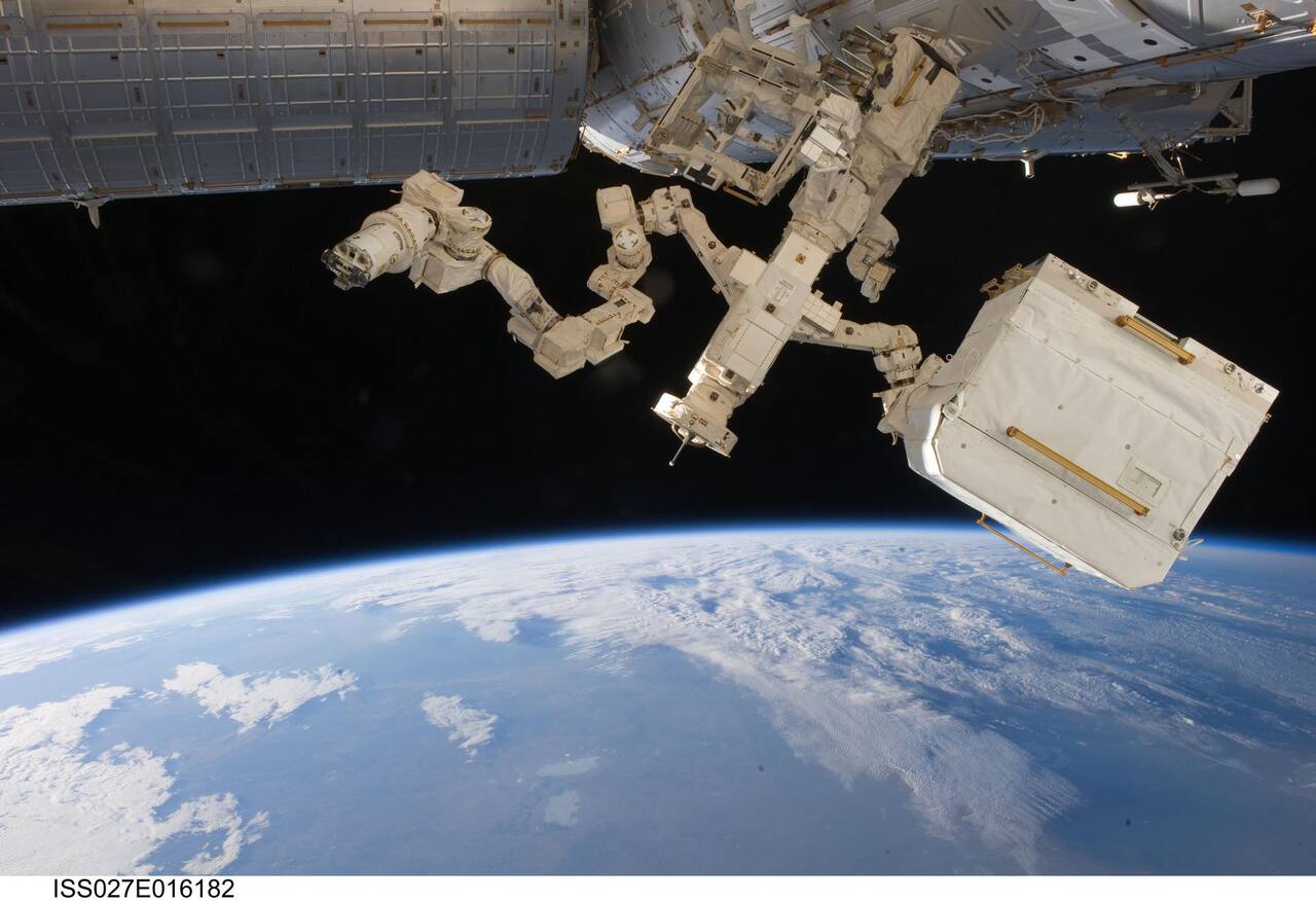 NASA. Public domain (NASA / US government work).
Overview
Section titled “Overview”A station the size of the ISS accumulates failed boxes, worn cables and jammed hinges faster than a spacewalk schedule can absorb them, and every hour of extravehicular activity carries suit consumables, crew fatigue and depressurization risk that a robot does not. Dextre, formally the Special Purpose Dexterous Manipulator, was built to take that maintenance load off the crew: inserting and extracting orbital replacement units, actuating hinge-like mechanisms on the truss, and manipulating and inspecting payloads that would otherwise need a suited astronaut at the work site [1].
The requirement that shaped the design was commonality, not novelty. Dextre mounts on Canadarm2 or on a station grapple fixture and shares that arm’s Power Data Grapple Fixture interface and Latching End Effector design, so it can be carried by Canadarm2 or anchor itself directly to the station [3]. The Space Station Remote Manipulator System whose joints and end effectors Dextre’s interfaces were built to match was itself still a preliminary design when its mechanism specification was written, with detail design in progress and force-moment sensing still under investigation [9]; the convergence on shared interfaces across both arms was a program decision to avoid a second qualification campaign, not a discovery made through flight experience.
Specifications
Section titled “Specifications”| Parameter | Value | Source |
|---|---|---|
| Arms | 2, 7 joints each | [1], [2] |
| Arm reach | 3.3 m straight-arm | [1] |
| Payload capacity per arm | 600 kg | [2], [1] |
| Body roll joint | 1 DOF at the waist | [2] |
| Motion resolution requirement | 2 mm | [2] |
| Joints total, including the flight spare arm | 21 | [3] |
Mission profile
Section titled “Mission profile”| Parameter | Value | Source |
|---|---|---|
| Host | International Space Station, on Canadarm2 or a station grapple fixture | [2] |
| Launch configuration | 9 separate components | |
| On-orbit assembly | about 6 h of EVA | |
| Station orbital replacement units designated for robotic servicing | about 250 | [2] |
| Of those, compatible with Dextre interfaces | about 200 |
Rows with no marker are from [3].
Each arm has three joints at the shoulder, one pitch at the elbow and three at the wrist [2].
End effector and tools
Section titled “End effector and tools”Each arm terminates in an ORU/Tool Changeout Mechanism carrying a parallel-jaw gripper compatible with H fixtures and micro fixtures, a retractable 7/16 inch socket drive, an extendable umbilical passing power, data and video to the grasped unit, a two-stop zoom camera and two lights [2]. A body-mounted tool holder carries four tools that the arms exchange without crew involvement, and two outriggers carry camera and light pan-tilt assemblies.
Payload interfaces are typed. The standard interface is a micro fixture, whose normal operating loads of 100 N and 85 N m bound the peak transient contact forces and moments allowed during a grasp; units with a micro-conical interface, such as the 6B avionics boxes, are handled instead through a separate Robot Micro-Conical Tool, whose offset makes the force-moment accommodation problem harder [1]. Heavier payloads are grasped directly at a grasp fixture. A dedicated H fixture on the station stabilizes the body during two-arm work [2].
Only one arm moves at a time, a power limit rather than a control limit [1]. The other holds a fixed grasp to provide a stable reference, since two arms sharing a compliant base would couple their position errors, and the 2 mm motion resolution requirement [2] does not survive that coupling.
Force-moment accommodation
Section titled “Force-moment accommodation”Each arm carries a six-axis force-moment sensor on the OTCM [1]. Force-Moment Accommodation closes an outer loop on that sensor so the arm complies with contact rather than driving through it. Commanded steady-state limits are 4 N of lateral force and 3.1 N m of lateral moment, excluding transients, within a user-selectable range of 0 to 111 N and 0 to 54 N m [1].
| Parameter | Value |
|---|---|
| Teleoperated positioning accuracy | 6 mm, 2.0 deg |
| Automatic incremental adjustment | 2 mm, 0.1 deg |
| ORU capture envelope | 5 cm lateral, 8 deg about any axis |
| Micro fixture operating limits | 100 N, 85 N m |
| Guide design load | 50 N, 50 N m |
| Transient force limit during bolt following | 12 N peak |
| Insertion force and moment resolution | 4 N, 2.37 N m |
| Gripper jaw closure | 15 to 20 s |
| Operator guideline on peak transients | 5 s maximum duration |
Source: [1].
The case for the control law is measurable. Three operators inserted a DDCU orbital replacement unit on the SPDM ground testbed with and without Force-Moment Accommodation [1]:
| Operator | Without FMA | With FMA |
|---|---|---|
| 1 | 1.5 mm/s, 5 min, peak 200 N and 12 N m | 5.5 mm/s, 2.0 min, peak 18 N and 25 N m |
| 2 | 0.5 mm/s, 17.5 min, peak 190 N and 45 N m | 5.5 mm/s, 2.0 min, peak 19 N and 24 N m |
| 3 | 1.5 mm/s, over 15 min, peak 220 N and 37 N m | 4.2 mm/s, 2.5 min, peak 16 N and 20 N m |
Source: [1].
Peak contact force falls by roughly an order of magnitude and insertion time by a factor of three to eight. Since orbital replacement units cannot be repaired on orbit, the peak force column is the binding number, not the time column, and the requirements verification program was built around demonstrating those interface loads rather than around task speed [3]. Ground testing is run inside a gravity envelope of plus or minus 3 degrees of attitude, within which gravity compensation holds residual force below 3 N and residual moment below 1 N m [1]; the testbed travels 5 ft vertically, 3 ft along the insertion axis and 1 ft laterally.
Thermal
Section titled “Thermal”Dextre and its payloads are maintained by heaters sized against eclipse. The Robotic Refueling Mission payload it hosts illustrates the allocations: two Shuttle heater feeds totalling 230 W at maximum voltage, about 216 W at nominal, each circuit controlled by two Elmwood mechanical thermostats in series switching between +25 and +30 C [4]. On ELC-4 the station provides two feeds totalling 290 W at maximum voltage, about 245 W nominal. Tool heaters are separately powered through the OTCM: 5 W per tool camera with two cameras per tool, and 10 W per tool electronics box, with thermostat set points of -25/-16 C for the cameras and -32/-26 C for the electronics [4].
Robotic Refueling Mission
Section titled “Robotic Refueling Mission”Dextre hosted the Robotic Refueling Mission series, which operated on representative satellite fuel valves including wire-locked caps, cutting safety wire, removing caps and transferring fluid [5]. RRM3 extended this to cryogenics.
| RRM3 parameter | Value | Source |
|---|---|---|
| Source and receiver dewar volume | 50 L and 10 L | [6], [19] |
| Methane load at launch | about 19 kg | [6] |
| Zero boil-off duration, ground plus orbit | 6 months | |
| Demonstrated on-orbit storage | 4 months | |
| Receiver dewar temperature | below 82 K | |
| Methane triple point | 90.7 K | |
| No-vent transfers demonstrated on the ground | 5 | |
| Autogenous pressurization cycle | 20 min | |
| Ground supply dewar | 450 liter DOT-rated Chart Microfueler | [7] |
| Methane purity requested / delivered | 99.9 / 98.2 percent | [7] |
| Launch | 5 December 2018 | [7] |
Rows with no marker are from [6].
Ground servicing with liquid methane imposed a 150 ft dynamic hazard control zone during testing, a 50 ft continuous control zone, a vent stack 35 ft from the work building and an 18 ft standoff for the command trailer [7]. Machine vision calibration for RRM3 held below 2 mm of error [5], and telerobotic operation required a minimum of 10 frames per second of video, with 24 preferred. Operations ran 16 to 20 hours per day with a three-person flight controller team and about twelve supporting staff at Goddard.
A related payload on the same servicing project, the Dextre Pointing Package, would have mounted rendezvous and docking sensors (a triangulation and time-of-flight lidar, a star tracker and a 6-DOF inertial measurement unit) on the arm to give closed-loop tracking of visiting vehicles on-orbit exposure that a laboratory testbed cannot reproduce, since a realistic rendezvous envelope spans kilometers of range and nearly the full sphere of attitude, tractable in a lab only below about 25 m [10]. The package did not fly.
The Canadian Space Agency operates Dextre jointly with NASA and is the organization responsible for its public technical information [12].
Ground operations
Section titled “Ground operations”Round-trip communication delay to the station is 5 to 6 seconds or more [8], so continuous force-reflecting teleoperation is not available and the Force-Moment Accommodation loop has to close on orbit rather than on the ground. Procedures are developed against a six-degree-of-freedom industrial robot at Goddard and an MDA ground trainer carrying SPDM-representative hardware [5]. A parallel line of work proposed running station arm operations from the ground entirely, driven by a task-level programming and control framework rather than direct teleoperation, on the reasoning that crew time is the scarcer resource when an arm moves slowly over long displacements [8]; that architecture was demonstrated only against a simulator, and nothing in the corpus shows it flown against the Mobile Servicing System.
Robotic cargo operations are long by EVA standards but cost no crew time. Dextre’s role inside the broader on-orbit servicing landscape, alongside other short-reach station manipulators, is one entry in NASA’s periodic survey of servicing, assembly and manufacturing capability, whose 2021 edition set the capability taxonomy that later editions still use [11].
Place in the Mobile Servicing System
Section titled “Place in the Mobile Servicing System”Canadarm2 supplies the reach. The agency table gives it 17 m, 1497 kg, seven joints with 540 deg of rotation each, and tip speeds of 37 cm/s unloaded and 2 cm/s loaded under ground control, against 15 m and 410 kg for the Shuttle arm [15]. Its seventh joint makes it kinematically redundant and symmetric about the elbow, so either end can be the base, which lets it walk between power-data grapple fixtures,. Closed-form inverse kinematics for the arm split the arm into three six-joint subchains with at most eight configurations each, solved by quadratics [14]. A 1987 trade study for the Mobile Transporter that carries the arm along the truss fixed the requirements to traverse every truss face and handle payloads over 100,000 kg, at a time when the arm design was still open [30]. The Spar simulation facility built for the Canadian Space Agency modeled both the SSRMS and the SPDM with flexible multibody contact dynamics, but reports no validation error [13]. Operator interfaces were compared on a Space Station mockup in 1994 with ten astronauts, a controls and displays test that measured nothing about arm performance [29].
Heritage and drive components
Section titled “Heritage and drive components”Dextre was verified largely as an assembly of previously qualified parts. The Shuttle arm end effector it descends from closes a three-cable snare by turning a ring through 80 deg and tolerates 4 in of lateral and axial misalignment, with the figures given as design requirements [28]. A 1987 survey of electromechanical drives for space manipulators compared ten transmission families on backlash, friction and stiffness, from untraceable prior tests [31]. The European Robotic Arm, the other station arm built to the same generation of interface thinking, uses a redundant motor driving a 454 to 1 epicyclic stage with torque ripple cut from roughly 15 percent to under 0.3 percent, qualified at unit level before the arm flew [27].
Other manipulators and servicing approaches
Section titled “Other manipulators and servicing approaches”Dextre is one of several flown or planned station manipulators, and the sources group them by what they were built to handle [21], [22].
- Large station arms. The European Robotic Arm serves the Russian segment because Canadarm2 and the Japanese arm cannot reach its base point and payload interfaces [26]. The Chinese station carries a core module arm and an experiment module arm; the design paper gives the core arm 10.5 m, 738 kg and 25,000 kg payload [24], while a state-run article gives 10.2 m [25], and NASA’s catalog carries both arms [23].
- Humanoid and free-flying robots. Robonaut 2 flew with 42 degrees of freedom, six checkout operations and first crew teleoperation in April 2013, with no task success rates reported [19]. A SPHERES docking and servicing payload set was tested only on a flat floor and in a reduced gravity aircraft [35]. Neither replaces external maintenance.
- Crew and ground teleoperation. Bilateral force-feedback control from the station to ground robots measured 20 to 30 ms round trip over S-band across 23 sessions [20], and three astronauts drove a rover over 11 hours from the station [34]. Dextre’s 5 to 6 s ground delay rules this approach out for contact operations.
- Next-generation arm. Canadarm3 for the Gateway is a proposed 8.5 m, 715 kg (estimated) design that has not been built [15], [33].
- Propellant transfer. A heated-wick pressurization concept for RRM3 was developed with liquid nitrogen at one g [18], and a hydrazine transfer subsystem for a servicing spacecraft was characterized with surrogate fluids [32].
RRM3 held methane for 165 days without venting, but its five ground transfers moved 9.5, 1, 8.5, 0.8 and over 10 liters, the second and fourth failing and the fifth ending in a liquid lock that ruptured a burst disk [17]. No cryogen was transferred on orbit.
What is not established
Section titled “What is not established”The Force-Moment Accommodation comparison is a single run per operator per condition, run without repetition because operators did not want to repeat the unassisted case, so the without-FMA numbers are as much a record of operator frustration as of a controlled baseline [1]. The SPDM ground testbed’s claimed match to a zero-gravity simulation rests on one comparison plot described only qualitatively, with no residual error reported [1]. The interface commonality argument between Dextre and Canadarm2, that clearing shared items by environment comparison alone is sufficient, is stated as the verification plan rather than shown to have worked, since the paper describing it was written while verification was still underway [3]. The proposed ground-control architecture for the Mobile Servicing System has no flight demonstration and no reported task times, delay compensation error or operator study [8]. RRM3’s central objective, cryogenic transfer in microgravity, was itself never exercised: fluid management at the transfer line inlet, no-vent transfer and freezing behavior of methane in zero g remain unanswered, and most of the ground campaign substituted argon and nitrogen for methane because of facility limits [6]. The Dextre Pointing Package’s pointing and sensor performance figures are simulation only, since the payload never flew [10]. The Canadarm3 figures are design targets, and the agency tables for Canadarm2 give no payload mass for the quoted speeds [15]. The agency pages carry no independently verified specification [16], and the two Chinese arm length figures are unreconciled [24], [25].
References
- Mukherji, R., Rey, D. A., Stieber, M. and Lymer, J. (2001). Special Purpose Dexterous Manipulator (SPDM) Advanced Control Features and Development Test Results
. International Symposium on Artificial Intelligence, Robotics and Automation in Space. Source
BibTeX
@inproceedings{mukherji2001special, title = {Special Purpose Dexterous Manipulator (SPDM) Advanced Control Features and Development Test Results}, author = {Mukherji, R. and Rey, D. A. and Stieber, M. and Lymer, John}, booktitle = {International Symposium on Artificial Intelligence, Robotics and Automation in Space}, address = {St-Hubert, Quebec}, year = {2001}, url = {https://roboshare.esa.int/i-SAIRAS/isairas2001/papers/Paper_AM104.pdf} } - Stieber, M. E., Hunter, D. G. and Abramovici, A. (1999). Overview of the Mobile Servicing System for the International Space Station
. International Symposium on Artificial Intelligence, Robotics and Automation in Space. Source
BibTeX
@inproceedings{stieber1999overview, title = {Overview of the Mobile Servicing System for the International Space Station}, author = {Stieber, M. E. and Hunter, D. G. and Abramovici, A.}, booktitle = {International Symposium on Artificial Intelligence, Robotics and Automation in Space}, address = {ESTEC, Noordwijk}, year = {1999}, url = {http://robotics.estec.esa.int/i-SAIRAS/isairas1999/s02-01.pdf} } - Bassett, D. A. and Abramovici, A. (1999). Special Purpose Dexterous Manipulator (SPDM) Requirements Verification
. International Symposium on Artificial Intelligence, Robotics and Automation in Space. Source
BibTeX
@inproceedings{bassett1999special, title = {Special Purpose Dexterous Manipulator (SPDM) Requirements Verification}, author = {Bassett, D. A. and Abramovici, A.}, booktitle = {International Symposium on Artificial Intelligence, Robotics and Automation in Space}, address = {ESTEC, Noordwijk}, year = {1999}, url = {http://robotics.estec.esa.int/i-SAIRAS/isairas1999/s02-02.pdf} } - Gregory, T. H. and Newman, M. (2011). Thermal Design Considerations of the Robotic Refueling Mission (RRM)
. International Conference on Environmental Systems, 20110013452. Source
BibTeX
@inproceedings{gregory2011thermal, title = {Thermal Design Considerations of the Robotic Refueling Mission (RRM)}, author = {Gregory, Teri H. and Newman, Miles}, booktitle = {International Conference on Environmental Systems}, number = {20110013452}, institution = {NASA}, year = {2011}, doi = {10.2514/6.2011-5072}, abstract = {The Robotic Refueling Mission (RRM) is a flight demonstration of the tasks required to perform robotic refueling of orbiting spacecraft. RRM will be mounted to an ExPress Adapter Plate (ExPA) for launch and installed onto the International Space Station (ISS) Express Logistics Carrier 4 (ELC4). RRM operations will be conducted using the Special Purpose Dexterous Manipulator (SPDM) robotic arm on the ISS with the ORU/Tool Changeout Mechanism (OTCM) for grasping tools and completing the refueling demonstration tasks. This paper presents the thermal considerations and design of the RRM including the tools required for the tasks.} } - Tomlinson, Z., Gallagher, W., Cassidy, J., Roberts, B., Facciol, K. and Easley, J. (2021). Lessons for Future In-Space Telerobotic Servicing from Robotic Refueling Mission
. IEEE Aerospace Conference, 20210022255. Source
BibTeX
@inproceedings{tomlinson2021lessons, title = {Lessons for Future In-Space Telerobotic Servicing from Robotic Refueling Mission}, author = {Tomlinson, Zakiya and Gallagher, William and Cassidy, Justin and Roberts, Brian and Facciol, Kristen and Easley, Joseph}, booktitle = {IEEE Aerospace Conference}, number = {20210022255}, pages = {1-17}, institution = {NASA}, year = {2021}, doi = {10.1109/aero53065.2022.9843499}, abstract = {The Robotic Refueling Mission (RRM) was a multi-phased technology development effort by the National Aeronautics & Space Administration (NASA) and the Canadian Space Agency (CSA). The program leveraged the existing robotic systems and expertise of the International Space Station (ISS) program and the tool design and satellite servicing expertise of NASA's Exploration & In-space Services (NExIS) Projects Division at Goddard Space Flight Center (GSFC) to evaluate new hardware and techniques for on-orbit telerobotic servicing. Between 2011 and 2022, two external ISS payloads housed over a dozen robotic tools and adapters designed to service a variety of existing and novel satellite interfaces. Robot operators at NASA's Johnson Space Center (JSC) and CSA used the Special Purpose Dexterous Manipulator (SPDM) to retrieve and operate these tools for tasks such as cutting wires or multi-layer insulation blanketing, removing valve caps, mating electrical connectors, transferring fluids, and performing visual inspections inside a vehicle. Each phase of RRM involved years of preparation. Tool and interface designs were prototyped and evaluated using both NASA and Canadian ground robotic systems. Procedures were developed by GSFC engineers and vetted in partnership with JSC and CSA robot operators. GSFC engineers were trained to provide real-time support during on-orbit operations. These preparatory efforts and the successful on-orbit evaluations yielded an array of lessons for future in-space telerobotic missions. Designing robotic tools for the space environment requires special consideration of materials, indicators, and differences between ground and flight use cases and environments. When there is a limited window for on-orbit operations, devoting time and high-fidelity hardware to ground testing can be critical. Needs during potential troubleshooting are more essential to camera view quality, frame rate, and position requirements than nominal operations. Detailed hardware manuals, nominal and contingency procedures, along with clearly defined operations team roles and protocols are vital for efficiency. RRM also demonstrated how the ISS can be utilized to increase the technology readiness levels required for future missions and led to additional technology partnerships between NExIS and the ISS program. The lessons from RRM are currently being applied to designs, operations concepts, and ground test methodology for missions such as On-orbit Servicing, Assembly, and Manufacturing 1 (OSAM-1) and Mars Sample Return.} } - Breon, S. R., Boyle, R. F., Francom, M. B., DeLee, C. H., Francis, J. J., Mustafi, S., Barfknecht, P. W., McGuire, J. M., Krenn, A. G., Zimmerli, G. A. and Hauser, D. M. (2020). Robotic Refueling Mission-3---an overview
. IOP Conference Series: Materials Science and Engineering. Source
BibTeX
@inproceedings{breon2020robotic, title = {Robotic Refueling Mission-3---an overview}, author = {Breon, S. R. and Boyle, R. F. and Francom, M. B. and DeLee, C. H. and Francis, J. J. and Mustafi, Shuvo and Barfknecht, P. W. and McGuire, J. M. and Krenn, A. G. and Zimmerli, G. A. and Hauser, D. M.}, booktitle = {IOP Conference Series: Materials Science and Engineering}, volume = {755}, pages = {012002}, year = {2020}, doi = {10.1088/1757-899x/755/1/012002}, abstract = {Abstract Robotic Refueling Mission-3 (RRM3) is an external payload on the International Space Station (ISS) to demonstrate the techniques for storing and transferring a cryogenic fuel on orbit. RRM3 was designed and built at the National Aeronautics and Space Administration/Goddard Space Flight Center (NASA/GSFC). Initial testing was performed at GSFC using liquid nitrogen and liquid argon. Final testing and flight fill of methane was performed at the NASA Kennedy Space Center (KSC) to take advantage of KSC’s facilities and expertise for handling a combustible cryogen. This paper gives an overview of the process and challenges of developing the payload and the results of its on-orbit performance.} } - Krenn, A., Stewart, M., Mitchell, D., Dixon, K. L., Mierzwa, M. and Breon, S. (2019). Flight Servicing of Robotic Refueling Mission 3
. IOP Conference Series: Materials Science and Engineering. Source
BibTeX
@inproceedings{krenn2019flight, title = {Flight Servicing of Robotic Refueling Mission 3}, author = {Krenn, Angela and Stewart, M. and Mitchell, D. and Dixon, Kyle L. and Mierzwa, M. and Breon, Susan}, booktitle = {IOP Conference Series: Materials Science and Engineering}, year = {2019}, url = {https://ntrs.nasa.gov/citations/20190027566}, abstract = {The Robotic Refueling Mission 3 (RRM3) payload launched aboard a SpaceX rocket en route to the International Space Station on December 5th, 2018. The Goddard Space Flight Center designed payload carried approximately 50 liters of liquid methane onboard, with a mission to demonstrate long term storage and transfer of the cryogenic fluid in microgravity. Kennedy Space Center (KSC) was tasked to design, fabricate, test, and operate a system equipped to fill an RRM3 dewar with liquid methane prior to launch. Though KSC has a rich history of fueling rockets and payloads, no such operations had previously been accomplished using liquid methane. As such, all of the hardware and processes had to be developed from scratch. The completed ground system design, along with the verification and validation testing will be outlined in this paper. Several challenges that were met and overcome during procurement of the high purity methane are described. In addition, budget restrictions prohibited fueling operations from occurring in traditional processing facilities. The unique and creative solutions which were required to maintain payload cleanliness during cryogenic servicing are also detailed.} } - Landzettel, K., Brunner, B., Schreiber, G., Steinmetz, B.-M. and Dupuis, E. (2001). MSS Ground Control Demo with MARCO
. International Symposium on Artificial Intelligence, Robotics and Automation in Space. Source
BibTeX
@inproceedings{landzettel2001mss, title = {MSS Ground Control Demo with MARCO}, author = {Landzettel, Klaus and Brunner, Bernhard and Schreiber, Gerhard and Steinmetz, Bernhard-Michael and Dupuis, Eric}, booktitle = {International Symposium on Artificial Intelligence, Robotics and Automation in Space}, address = {St-Hubert, Quebec}, year = {2001}, url = {https://roboshare.esa.int/i-SAIRAS/isairas2001/papers/Paper_EU047.pdf} } - Kumar, R. and Hayes, R. (1991). System requirements and design features of Space Station Remote Manipulator System mechanisms
. Aerospace Mechanisms Symposium, 19910015291. Source
BibTeX
@inproceedings{kumar1991system, title = {System requirements and design features of Space Station Remote Manipulator System mechanisms}, author = {Kumar, Rajnish and Hayes, Robert}, booktitle = {Aerospace Mechanisms Symposium}, number = {19910015291}, institution = {NASA}, year = {1991}, url = {https://ntrs.nasa.gov/citations/19910015291}, abstract = {The Space Station Remote Manipulator System (SSRMS) is a long robotic arm for handling large objects/payloads on the International Space Station Freedom. The mechanical components of the SSRMS include seven joints, two latching end effectors (LEEs), and two boom assemblies. The joints and LEEs are complex aerospace mechanisms. The system requirements and design features of these mechanisms are presented. All seven joints of the SSRMS have identical functional performance. The two LEES are identical. This feature allows either end of the SSRMS to be used as tip or base. As compared to the end effector of the Shuttle Remote Manipulator System, the LEE has a latch and umbilical mechanism in addition to the snare and rigidize mechanisms. The latches increase the interface preload and allow large payloads (up to 116,000 Kg) to be handled. The umbilical connectors provide power, data, and video signal transfer capability to/from the SSRMS.} } - Naasz, B. J., Strube, M., Van Eepoel, J., Barbee, B. W. and Getzandanner, K. M. (2011). Satellite Servicing's Autonomous Rendezvous and Docking Testbed on the International Space Station
. Annual AAS Rocky Mountain Section Guidance and Control Conference, 20180000044. Source
BibTeX
@inproceedings{naasz2011satellite, title = {Satellite Servicing's Autonomous Rendezvous and Docking Testbed on the International Space Station}, author = {Naasz, Bo J. and Strube, Matthew and Van Eepoel, John and Barbee, Brent W. and Getzandanner, Kenneth M.}, booktitle = {Annual AAS Rocky Mountain Section Guidance and Control Conference}, number = {20180000044}, institution = {NASA}, address = {Breckenridge, CO}, year = {2011}, url = {https://ntrs.nasa.gov/citations/20180000044}, abstract = {The Space Servicing Capabilities Project (SSCP) at NASA's Goddard Space Flight Center (GSFC) has been tasked with developing systems for servicing space assets. Starting in 2009, the SSCP completed a study documenting potential customers and the business case for servicing, as well as defining several notional missions and required technologies. In 2010, SSCP moved to the implementation stage by completing several ground demonstrations and commencing development of two International Space Station (ISS) payloads-the Robotic Refueling Mission (RRM) and the Dextre Pointing Package (DPP)--to mitigate new technology risks for a robotic mission to service existing assets in geosynchronous orbit. This paper introduces the DPP, scheduled to fly in July of 2012 on the third operational SpaceX Dragon mission, and its Autonomous Rendezvous and Docking (AR&D) instruments. The combination of sensors and advanced avionics provide valuable on-orbit demonstrations of essential technologies for servicing existing vehicles, both cooperative and non-cooperative.} } - Arney, D., Sutherland, R., Mulvaney, J., Steinkoenig, D., Stockdale, C. and Farley, M. (2021). On-orbit Servicing, Assembly, and Manufacturing (OSAM) State of Play, 2021 Edition
. NASA, 20210022660. Source
BibTeX
@techreport{arney2021orbit, title = {On-orbit Servicing, Assembly, and Manufacturing (OSAM) State of Play, 2021 Edition}, author = {Arney, Dale and Sutherland, Richard and Mulvaney, John and Steinkoenig, Devon and Stockdale, Christopher and Farley, Mason}, number = {20210022660}, institution = {NASA}, year = {2021}, url = {https://ntrs.nasa.gov/citations/20210022660}, abstract = {This document compiles and organizes the current state of OSAM missions, capabilities, and developments. Understanding where the set of capabilities currently stand will help mission designers incorporate OSAM technologies into their concepts, create the starting point for technology development plans and roadmaps, and provide technologists a survey of the field they are developing. The authors recognize that this capability is broad and that they are unlikely to have captured everything that has been or is being done in the area on the first attempt. As a result, a new version of the OSAM State of Play will be released periodically (perhaps annually).} } - Ma, O., Buhariwala, K., Roger, N., MacLean, J. and Carr, R. (1997). MDSF — A generic development and simulation facility for flexible, complex robotic systems
. Robotica. Source
BibTeX
@article{ma1997mdsf, title = {MDSF — A generic development and simulation facility for flexible, complex robotic systems}, author = {Ma, Ou and Buhariwala, Kerman and Roger, Neil and MacLean, John and Carr, Robert}, journal = {Robotica}, volume = {15}, pages = {49-62}, year = {1997}, doi = {10.1017/s0263574797000076}, abstract = {MDSF is a generic manipulator development and simulation facility developed by Spar Aerospace Limited, as a prime contractor to the Canadian Space Agency. It is an integral part of Canada's contribution to the International Space Station (ISS) program. MDSF is capable of simulating general robotic systems with complex and flexible structures undergoing all kinds of tasks including payload hand-over and contact with the environment. Rigorous validation and configuration control have been imposed throughout the development course of the simulation facility. Examples of current applications in the ISS program are included.} } - Crane, C. D. I., Duffy, J. and Carnahan, T. (1991). A kinematic analysis of the Space Station remote manipulator system (SSRMS)
. Journal of Robotic Systems, 19910069677. Source
BibTeX
@article{crane1991kinematic, title = {A kinematic analysis of the Space Station remote manipulator system (SSRMS)}, author = {Crane, Carl D., III and Duffy, Joseph and Carnahan, Tim}, journal = {Journal of Robotic Systems}, volume = {8}, number = {19910069677}, pages = {637-658}, institution = {NASA}, year = {1991}, doi = {10.1002/rob.4620080505}, abstract = {Abstract An efficient reverse analysis of three 6‐degree‐of‐freedom (dof) subchains of the 7‐dof SSRMS is presented. The first subchain is formed by locking the seventh joint. The second subchain is formed by locking the second joint, while the third subchain is formed by locking the first joint (the grounded joint is counted as the first joint in the chain). There are a maximum of eight different arm configurations in each of the three subchains, and these were determined by employing a computer‐efficient algorithm, which required the rooting of only at most quadratic polynomials. The algorithms were implemented, and the SSRMS was employed in an animated environment to perform and practice a number of useful tasks for space station servicing. The locking of the second joint has the advantage in that an operator could, at the outset, choose the orientation of the plane that contains the two longest links (the upper arm and forearm) so as to avoid collisions with obstacles. However, it has the disadvantage that when the second joint angle equals 0° or 180°, the manipulator is in a singularity configuration (a singularity analysis of the SSRMS is presented in a second article). It is interesting to note that this plane can also be oriented by specifying the first joint angle. This has the distinct advantage that the plane can be oriented arbitrarily and, in this way, the singularity is avoided.} } - (2026). CSA: Comparative table of Canadarm, Canadarm2 and Canadarm3. asc-csa.gc.ca/eng/iss/canadarm2/canadarm-canadarm2-canadarm3-comparat...
BibTeX
@misc{csacomparative, title = {CSA: Comparative table of Canadarm, Canadarm2 and Canadarm3}, organization = {asc-csa.gc.ca}, year = {2026}, url = {https://www.asc-csa.gc.ca/eng/iss/canadarm2/canadarm-canadarm2-canadarm3-comparative-table.asp} } - (2026). CSA: Canadarm2. asc-csa.gc.ca/eng/iss/canadarm2
BibTeX
@misc{csacanadarm2, title = {CSA: Canadarm2}, organization = {asc-csa.gc.ca}, year = {2026}, url = {https://www.asc-csa.gc.ca/eng/iss/canadarm2/} } - Boyle, R., Breon, S., Francom, M., DeLee, H., Francis, J., Mustafi, S., Barfknecht, P., McGuire, J., Krenn, A. and Zimmerli, G. (2019). Robotic Refueling Mission 3: Cryogenic Demonstration Subsystem Operations, 20190027535. ntrs.nasa.gov/citations/20190027535
BibTeX
@misc{boyle2019robotic, title = {{Robotic Refueling Mission 3}: Cryogenic Demonstration Subsystem Operations}, author = {Boyle, Rob and Breon, Susan and Francom, Matt and DeLee, Hudson and Francis, John and Mustafi, Shuvo and Barfknecht, Pete and McGuire, Jill and Krenn, Angela and Zimmerli, Greg}, howpublished = {Presentation at the NASA Goddard Space Flight Center}, number = {20190027535}, year = {2019}, url = {https://ntrs.nasa.gov/citations/20190027535}, abstract = {The Robotic Refueling Mission 3 (RRM3) payload was installed on the International Space Station (ISS) in December 2018. Its Cryogenic Demonstation Subsystem (CDS) was loaded with 19 kilograms of liquid methane, for demonstration of on-orbit storage and transfer. We provide a short description of the design and ground testing of the CDS, and then discuss the on-orbit operations through the first half of 2019.} } - Boyle, R., DiPirro, M., Tuttle, J., Francis, J., Mustafi, S., Li, X., Barfknecht, P., DeLee, C. H. and McGuire, J. (2015). Cryogenic Autogenous Pressurization Testing for Robotic Refueling Mission 3, 20150016072. ntrs.nasa.gov/citations/20150016072
BibTeX
@misc{boyle2015cryogenic, title = {Cryogenic Autogenous Pressurization Testing for {Robotic Refueling Mission 3}}, author = {Boyle, Rob and DiPirro, M. and Tuttle, J. and Francis, John and Mustafi, Shuvo and Li, X. and Barfknecht, Pete and DeLee, C. H. and McGuire, Jill}, howpublished = {Presentation at the NASA Goddard Space Flight Center}, number = {20150016072}, year = {2015}, url = {https://ntrs.nasa.gov/citations/20150016072}, abstract = {A wick-heater system has been selected for use to pressurize the Source Dewar of the Robotic Refueling Mission Phase 3 on-orbit cryogen transfer experiment payload for the International Space Station. Experimental results of autogenous pressurization of liquid argon and liquid nitrogen using a prototype wick-heater system are presented. The wick-heater generates gas to increase the pressure in the tank while maintaining a low bulk fluid temperature. Pressurization experiments were performed in 2013 to characterize the performance of the wick heater. This paper describes the experimental setup, pressurization results, and analytical model correlations.} } - Ahlstrom, T. D., Diftler, M. E., Berka, R. B., Badger, J. M., Yayathi, S., Curtis, A. W. and Joyce, C. A. (2013). Robonaut 2 on the International Space Station: Status Update and Preparations for IVA Mobility
. AIAA SPACE Conference. Source
BibTeX
@inproceedings{ahlstrom2013robonaut, title = {Robonaut 2 on the International Space Station: Status Update and Preparations for IVA Mobility}, author = {Ahlstrom, Thomas D. and Diftler, Myron E. and Berka, Reginald B. and Badger, Julia M. and Yayathi, Sandeep and Curtis, Andrew W. and Joyce, Charles A.}, booktitle = {AIAA SPACE Conference}, address = {San Diego, California}, year = {2013}, doi = {10.2514/6.2013-5340}, abstract = {Robotics engineers, ground controllers and International Space Station (ISS) crew have been running successful experiments using Robonaut 2 (R2) on-board the ISS for more than a year. This humanoid upper body robot continues to expand its list of achievements and its capabilities to safely demonstrate maintenance and servicing tasks while working alongside human crewmembers. The next phase of the ISS R2 project will transition from a stationary Intra Vehicular Activity (IVA) upper body using a power/data umbilical, to an IVA mobile system with legs for repositioning, a battery backpack power supply, and wireless communications. These upgrades will enable the R2 team to evaluate hardware performance and to develop additional control algorithms and control verification techniques with R2 inside the ISS in preparation for the Extra Vehicular Activity (EVA) phase of R2 operations. As R2 becomes more capable in assisting with maintenance tasks, with minimal supervision, including repositioning itself to different work sites, the ISS crew will be burdened with fewer maintenance chores, leaving them more time to conduct other activities. R2's developers at the Johnson Space Center (JSC) are preparing the R2 IVA mobility hardware and software upgrades for delivery to the ISS in late 2013. This paper summarizes R2 ISS achievements to date, briefly describes the R2 IVA mobility upgrades, and discusses the R2 IVA mobility objectives and plans.} } - Artigas, J., Riecke, C., Weber, B., Stelzer, M., Balachandran, R., Schaetzle, S., Bayer, R., Steinmetz, B.-M., Vogel, J., Brunner, B., Albu-Schäffer, A., Guk, M., Zaborovskyi, V., Kondratiev, A., Muliukha, V., Silinenko, A. and Shmakov, O. (2016). Force-Feedback Teleoperation of On-Ground Robots from the International Space Station in the Frame of the KONTUR-2 Experiment
. International Symposium on Artificial Intelligence, Robotics and Automation in Space. Source
BibTeX
@inproceedings{artigas2016force, title = {Force-Feedback Teleoperation of On-Ground Robots from the International Space Station in the Frame of the KONTUR-2 Experiment}, author = {Artigas, Jordi and Riecke, Cornelia and Weber, Bernhard and Stelzer, Martin and Balachandran, Ribin and Schaetzle, Simon and Bayer, Ralph and Steinmetz, Bernhard-Michael and Vogel, Jörg and Brunner, Bernhard and Albu-Schäffer, Alin and Guk, M. and Zaborovskyi, V. and Kondratiev, A. and Muliukha, V. and Silinenko, A. and Shmakov, O.}, booktitle = {International Symposium on Artificial Intelligence, Robotics and Automation in Space}, pages = {1166-1173}, year = {2016}, doi = {10.1109/icra.2016.7487246}, abstract = {This paper presents a new robot controller for space telerobotics missions specially designed to meet the requirements of KONTUR-2, a German & Russian telerobotics mission that addressed scientific and technological questions for future planetary explorations. In KONTUR-2, Earth and ISS have been used as a test-bed to evaluate and demonstrate a new technology for real-time telemanipulation from space. During the August 2015' experiments campaign, a cosmonaut teleoperated a robot manipulator located in Germany, using a force-feedback joystick from the Russian segment of the International Space Station (ISS). The focus of the paper is on the design and performance of the bilateral controller between ISS joystick and Earth robot. The controller is based on a 4-Channels architecture in which stability is guaranteed through passivity and the Time Delay Power Network (TDPN) concept. We show how the proposed approach successfully fulfills mission requirements, specially those related to system operation through space links and internet channels, involving time delays and data losses of different nature.} } - Alizadeh, A. and Zhu, Z. H. (2024). A comprehensive survey of space robotic manipulators for on-orbit servicing
. Frontiers in Robotics and AI. Source
BibTeX
@article{alizadeh2024comprehensive, title = {A comprehensive survey of space robotic manipulators for on-orbit servicing}, author = {Alizadeh, Ali and Zhu, Zheng H.}, journal = {Frontiers in Robotics and AI}, volume = {11}, pages = {1470950}, year = {2024}, doi = {10.3389/frobt.2024.1470950}, abstract = {On-Orbit Servicing (OOS) robots are transforming space exploration by enabling vital maintenance and repair of spacecraft directly in space. However, achieving precise and safe manipulation in microgravity necessitates overcoming significant challenges. This survey delves into four crucial areas essential for successful OOS manipulation: object state estimation, motion planning, and feedback control. Techniques from traditional vision to advanced X-ray and neural network methods are explored for object state estimation. Strategies for fuel-optimized trajectories, docking maneuvers, and collision avoidance are examined in motion planning. The survey also explores control methods for various scenarios, including cooperative manipulation and handling uncertainties, in feedback control. Additionally, this survey examines how Machine learning techniques can further propel OOS robots towards more complex and delicate tasks in space.} } - Papadopoulos, E., Aghili, F., Ma, O. and Lampariello, R. (2021). Robotic Manipulation and Capture in Space: A Survey
. Frontiers in Robotics and AI. Source
BibTeX
@article{papadopoulos2021robotic, title = {Robotic Manipulation and Capture in Space: A Survey}, author = {Papadopoulos, Evangelos and Aghili, Farhad and Ma, Ou and Lampariello, Roberto}, journal = {Frontiers in Robotics and AI}, volume = {8}, pages = {686723}, year = {2021}, doi = {10.3389/frobt.2021.686723}, abstract = {Space exploration and exploitation depend on the development of on-orbit robotic capabilities for tasks such as servicing of satellites, removing of orbital debris, or construction and maintenance of orbital assets. Manipulation and capture of objects on-orbit are key enablers for these capabilities. This survey addresses fundamental aspects of manipulation and capture, such as the dynamics of space manipulator systems (SMS), i.e., satellites equipped with manipulators, the contact dynamics between manipulator grippers/payloads and targets, and the methods for identifying properties of SMSs and their targets. Also, it presents recent work of sensing pose and system states, of motion planning for capturing a target, and of feedback control methods for SMS during motion or interaction tasks. Finally, the paper reviews major ground testing testbeds for capture operations, and several notable missions and technologies developed for capture of targets on-orbit.} } - Mulvaney, J., Arney, D., Williams, C., Morel, J., Stockdale, C., Whitlock, C. and Balaji, V. (2025). In-Space Servicing, Assembly, and Manufacturing (ISAM) State of Play, 2025 Edition
. NASA, 20250008988. Source
BibTeX
@techreport{nasa2025space, title = {In-Space Servicing, Assembly, and Manufacturing (ISAM) State of Play, 2025 Edition}, author = {Mulvaney, John and Arney, Dale and Williams, Christina and Morel, Jose and Stockdale, Christopher and Whitlock, Christopher and Balaji, Vishruth}, number = {20250008988}, institution = {NASA}, year = {2025}, url = {https://ntrs.nasa.gov/citations/20250008988}, abstract = {The future of spaceflight will yield increasingly more ambitious missions to support civil, national security, and commercial space sectors. Achieving some of these missions will not be feasible by launching an integrated, fully functioning system on a single launch vehicle. Future science and human exploration missions will require payloads that are larger than any foreseeable launch vehicle fairing, national security missions will require persistent assets that are mobile and resilient, and commercial space missions will require cost-effective ways to update to the latest technology on orbit. In-space Servicing, Assembly, and Manufacturing (ISAM) can vastly expand the performance, availability, and lifetime of space systems compared to the traditional paradigm of launching an asset with no intent to ever interact with it again. ISAM capabilities foster an ecosystem that changes the space operations paradigm, creating the foundation for sustainable exploration and serving as a multiplier for other capabilities like space logistics, power generation, and reusability. Previous achievements in ISAM have enabled ambitious human and robotic space missions. The assembly, operation, and maintenance of NASA’s International Space Station (ISS); servicing missions to the Hubble Space Telescope (HST); and Northrop Grumman’s Mission Extension Vehicle (MEV) demonstrate the dramatic operational missions that can be achieved using ISAM capabilities. Many current and upcoming flight demonstrations are advancing areas that will enable the next generation of civil, national security, and commercial space missions. This document describes the current state of ISAM missions, activities, and technologiesto the best ability of the authors. Compiling and organizing the available ISAM capabilities will help mission designers incorporate ISAM technologies into their concepts, create the starting point for technology development plans and roadmaps, and provide technologists a survey of the field they are developing. This document divides the ISAM capabilities into 11 functional capability areas that describe the functions or activities that can be performed in space using ISAM.} } - Li, D. and Wang, Y. (2015). Overview of the Chinese Space Station Manipulator
. AIAA SPACE Conference. Source
BibTeX
@inproceedings{li2015overview, title = {Overview of the Chinese Space Station Manipulator}, author = {Li, Daming and Wang, Yaobing}, booktitle = {AIAA SPACE Conference}, year = {2015}, doi = {10.2514/6.2015-4540}, abstract = {The Chinese Space Station Manipulator system (CSSM) is designed for the missions of relocking spacecraft sections, docking assistance, installing equipment, and maintaining the space station. Therefore, it will lay a foundation for the construction of the Chinese Space Station (CSS). The CSSM system, consisting of two robotic arms, is featured with a high degree of manipulation accuracy, reliability and load capability. Since it is a highly integrated robotic system, combining technologies of mechanics, electronics, thermotics, vision and computer control, the development of the Space Station faces many technical challenges and, therefore, the design and implementation of the robotic system is also challenging. This paper presents an introduction of the Core Space Station Cabin’s Manipulator (CSSCM) which is also referred to as the Chinese Space Station Manipulator. As the major arm of the two-arm CSSM system, the manipulator is a seven degree-of-freedom redundant arm with a distributed control system and movable base system. The paper also describes highlights of eight key technologies of the robotic arm, such as a high-precision servo control and a multi-constrained trajectory planning capability. Our study has shown that the CSSCM design has satisfactorily completed and the program has entered into the manufacturing phase.} } - (2026). CNSA: The two robotic arms of the China Space Station. cnsa.gov.cn/n6758968/n6758973/c10388340/content.html
BibTeX
@misc{cnsatwo, title = {CNSA: The two robotic arms of the China Space Station}, organization = {cnsa.gov.cn}, year = {2026}, url = {https://www.cnsa.gov.cn/n6758968/n6758973/c10388340/content.html} } - European Space Agency. (2021). European Robotic Arm: The International Space Station's Latest Upgrade
. ESA Human and Robotic Exploration. Source
BibTeX
@techreport{esa2021european, title = {European Robotic Arm: The International Space Station's Latest Upgrade}, author = {{European Space Agency}}, institution = {ESA Human and Robotic Exploration}, year = {2021}, url = {https://esamultimedia.esa.int/docs/science/ERA_brochure_EN.pdf} } - Baker, F. C., Favre, E., Mozzon, J.-M., Crausaz, A. and Juriens, P. (1999). European Robotic Arm (ERA) Manipulator Joint System Motor Unit and Tribological Brake
. European Space Mechanisms and Tribology Symposium. Source
BibTeX
@inproceedings{baker1999european, title = {European Robotic Arm (ERA) Manipulator Joint System Motor Unit and Tribological Brake}, author = {Baker, F. C. and Favre, E. and Mozzon, J.-M. and Crausaz, A. and Juriens, P.}, booktitle = {European Space Mechanisms and Tribology Symposium}, address = {Toulouse}, year = {1999}, url = {https://www.esmats.eu/esmatspapers/pastpapers/pdfs/1999/baker.pdf} } - Daniell, R. G. and Sachdev, S. S. (1982). The Design and Development of an End Effector for the Shuttle Remote Manipulator System
. Aerospace Mechanisms Symposium, 19820015473. Source
BibTeX
@inproceedings{daniell1982design, title = {The Design and Development of an End Effector for the Shuttle Remote Manipulator System}, author = {Daniell, R. G. and Sachdev, S. S.}, booktitle = {Aerospace Mechanisms Symposium}, number = {19820015473}, institution = {NASA}, year = {1982}, url = {https://ntrs.nasa.gov/citations/19820015473}, abstract = {The design requirements, the design, and qualification and development test problems encountered on the Remote Manipulator End Effector are described. The constraints and interfaces with the arm, the Orbiter, and the payload are identified. The design solution to meet the requirements is a unique device that provides a soft-docking feature termed capture and a hard-docking feature termed rigidization.} } - Ehrenstrom, W. A., Forrester, P. and Swaney, C. (1994). International Space Station Alpha Remote Manipulator System Workstation Controls Test Report
. NASA Johnson Space Center, NASA TM-104796. Source
BibTeX
@techreport{ehrenstrom1994international, title = {International Space Station Alpha Remote Manipulator System Workstation Controls Test Report}, author = {Ehrenstrom, William A. and Forrester, Patrick and Swaney, Colin}, number = {NASA TM-104796}, institution = {NASA Johnson Space Center}, year = {1994}, url = {https://ntrs.nasa.gov/citations/19940030975}, abstract = {Previous development testing for the space station remote manipulator system workstation controls determined the need for hardware controls for the emergency stop, brakes on/off, and some camera functions. This report documents the results of an evaluation to further determine control implementation requirements, requested by the Canadian Space Agency (CSA), to close outstanding review item discrepancies. This test was conducted at the Johnson Space Center's Space Station Mockup and Trainer Facility in Houston, Texas, with nine NASA astronauts and one CSA astronaut as operators. This test evaluated camera iris and focus, back-up drive, latching end effector release, and autosequence controls using several types of hardware and software implementations. Recommendations resulting from the testing included providing guarded hardware buttons to prevent accidental actuation, providing autosequence controls and back-up drive controls on a dedicated hardware control panel, and that 'latch on/latch off', or on-screen software, controls not be considered. Generally, the operators preferred hardware controls although other control implementations were acceptable. The results of this evaluation will be used along with further testing to define specific requirements for the workstation design.} } - Carroll, T. W. (1987). The design and development of a mobile transporter system for the Space Station Remote Manipulator System
. NASA, 19870020432. Source
BibTeX
@techreport{carroll1987design, title = {The design and development of a mobile transporter system for the Space Station Remote Manipulator System}, author = {Carroll, Thomas W.}, number = {19870020432}, institution = {NASA}, year = {1987}, url = {https://ntrs.nasa.gov/citations/19870020432}, abstract = {The analyses, selection process, and conceptual design of potential candidate Mobile Transporter (MT) systems to move the Space Station Remote Manipulator System (SSRMS) about the exposed faces of the Space Station truss structure are described. The actual requirements for a manipulator system on the space station are discussed, including potential tasks to be performed. The SSRMS operating environment and control methods are analyzed with potential design solutions highlighted. Three general categories of transporter systems are identified and analyzed. Several design solution have emerged that will satisfy these requirements. Their relative merits are discussed, and unique variations in each system are rated for functionality.} } - Chun, W. and Brunson, P. (1987). Actuators for a Space Manipulator
. NASA, 19890000730. Source
BibTeX
@techreport{chun1987actuators, title = {Actuators for a Space Manipulator}, author = {Chun, W. and Brunson, P.}, number = {19890000730}, institution = {NASA}, year = {1987}, url = {https://ntrs.nasa.gov/citations/19890000730}, abstract = {The robotic manipulator can be decomposed into distinct subsytems. One particular area of interest of mechanical subsystems is electromechanical actuators (or drives). A drive is defined as a motor with an appropriate transmission. An overview is given of existing, as well as state-of-the-art drive systems. The scope is limited to space applications. A design philosophy and adequate requirements are the initial steps in designing a space-qualified actuator. The focus is on the d-c motor in conjunction with several types of transmissions (harmonic, tendon, traction, and gear systems). The various transmissions will be evaluated and key performance parameters will be addressed in detail. Included in the assessment is a shuttle RMS joint and a MSFC drive of the Prototype Manipulator Arm. Compound joints are also investigated. Space imposes a set of requirements for designing a high-performance drive assembly. Its inaccessibility and cryogenic conditions warrant special considerations. Some guidelines concerning these conditions are present. The goal is to gain a better understanding in designing a space actuator.} } - Coll, G. T., Webster, G. K., Pankiewicz, O. K., Schlee, K. L., Aranyos, T. J., Nufer, B. M., Fothergill, J. B., Tamasy, G. J., Kandula, M., Felt, A. M. and Hicks, N. G. (2020). NASA's Exploration and In-Space Services (NExIS) Division OSAM-1 Propellant Transfer Subsystem Progress 2020
. AIAA Propulsion and Energy Forum, 20205004116. Source
BibTeX
@inproceedings{coll2020nasa, title = {NASA's Exploration and In-Space Services (NExIS) Division OSAM-1 Propellant Transfer Subsystem Progress 2020}, author = {Coll, Gregory T. and Webster, Graham K. and Pankiewicz, Oliver K. and Schlee, Keith L. and Aranyos, Thomas J. and Nufer, Brian M. and Fothergill, Jenna B. and Tamasy, Gabor J. and Kandula, Max and Felt, Amy M. and Hicks, Neil G.}, booktitle = {AIAA Propulsion and Energy Forum}, number = {20205004116}, institution = {NASA}, year = {2020}, doi = {10.2514/6.2020-3795}, abstract = {National Aeronautics and Space Administration (NASA)’s Exploration and In-Space Services (NExIS) Division of Goddard Space Flight Center has been developing technology for the On-orbit Servicing, Assembly and Manufacturing Mission 1 (OSAM-1) to robotically refuel heritage and new satellites on-orbit. OSAM-1, formerly known as Restore-L, successfully passed an important NASA milestone called Key Decision Point-C (KDP-C), receiving agency-level approval for its implementation. The decision point also establishes the mission’s official schedule and budget. The OSAM-1 spacecraft, Servicing Payload and the Space Infrastructure Dexterous Robot (SPIDER) payload will refuel a satellite in space, assemble a communications antenna and manufacture a beam. By demonstrating these capabilities, the mission is advancing never-before tested technologies for use in future missions (by NASA and other government organizations and private industry). The mission is funded by the Technology Demonstration Missions program within NASA’s Space Technology Mission Directorate. This paper covers a review of servicing extensibility and critical technologies that are being developed within NExIS with a focus on the fluid transfer refueling technology within the framework of the Propellant Transfer Subsystem (PTS). An overview of the planned initial technology demonstration servicing mission via the OSAM-1 Space Vehicle is provided as an extension of the technology development progress reported in 20181, and 20192. The general objectives, challenges, and key technologies are presented as an introduction to the context of the OSAM-1 mission, and a precursor to the OSAM-1 PTS specific development status. Development and progress of the Hose Management Assembly (HMA) and Propellant Transfer Assembly (PTA) are discussed. HMA risk reduction test results including those of thermal vacuum testing are presented. Important analytical results are discussed and progress of drawings and procedures developed for the fabrication and testing phase are shown. A summary of the PTS overall verification status and design activities prepared for the critical design peer review are presented. Procurement progress is shown with status on long, medium, and short term efforts to acquire the hardware required to support the mission objectives. Technology development, challenges, and testing status are discussed with particular regard to the OSAM-1 specific key assemblies including the PTA and HMA along with the overall integrated flight mockup of the spacecraft to client fluid transfer testing conducted in the servicing testbeds. The paper concludes with key milestones leading to the goal of on-orbit refueling to be demonstrated in 2024. The overall mission Launch Readiness Date (LRD) has been realigned to accommodate budget profiles and incorporation of additional on-orbit assembly and manufacturing demonstration efforts.} } - (2020). CSA: About Canadarm3. asc-csa.gc.ca/eng/canadarm3/about.asp
BibTeX
@misc{csaabout, title = {CSA: About Canadarm3}, organization = {asc-csa.gc.ca}, year = {2020}, url = {https://www.asc-csa.gc.ca/eng/canadarm3/about.asp} } - Bualat, M., Schreckenghost, D., Pacis, E., Fong, T., Kalar, D. and Beutter, B. (2014). Results from Testing Crew-Controlled Surface Telerobotics on the International Space Station
. iSAIRAS - International Symposium on Artificial Intelligence, Robotics and Automation in Space, 20150007985. Source
BibTeX
@inproceedings{bualat2014results, title = {Results from Testing Crew-Controlled Surface Telerobotics on the International Space Station}, author = {Bualat, Maria and Schreckenghost, Debra and Pacis, Estrellina and Fong, Terrence and Kalar, Donald and Beutter, Brent}, booktitle = {iSAIRAS - International Symposium on Artificial Intelligence, Robotics and Automation in Space}, number = {20150007985}, institution = {NASA}, address = {Montreal, Quebec}, year = {2014}, url = {https://ntrs.nasa.gov/citations/20150007985}, abstract = {During Summer 2013, the Intelligent Robotics Group at NASA Ames Research Center conducted a series of tests to examine how astronauts in the International Space Station (ISS) can remotely operate a planetary rover. The tests simulated portions of a proposed lunar mission, in which an astronaut in lunar orbit would remotely operate a planetary rover to deploy a radio telescope on the lunar far side. Over the course of Expedition 36, three ISS astronauts remotely operated the NASA "K10" planetary rover in an analogue lunar terrain located at the NASA Ames Research Center in California. The astronauts used a "Space Station Computer" (crew laptop), a combination of supervisory control (command sequencing) and manual control (discrete commanding), and Ku-band data communications to command and monitor K10 for 11 hours. In this paper, we present and analyze test results, summarize user feedback, and describe directions for future research.} } - Miller, D. L. (2015). Development of Resource-Constrained Sensors and Actuators for In-Space Satellite Docking and Servicing. Source
BibTeX
@mastersthesis{miller2015development, title = {Development of Resource-Constrained Sensors and Actuators for In-Space Satellite Docking and Servicing}, author = {Miller, Duncan L.}, school = {Massachusetts Institute of Technology}, type = {S.M. thesis}, year = {2015}, url = {https://dspace.mit.edu/handle/1721.1/98805} } - (2026). CSA: Dextre. asc-csa.gc.ca/eng/iss/dextre
BibTeX
@misc{csadextre,
  title = {CSA: Dextre},
  organization = {asc-csa.gc.ca},
  year = {2026},
  url = {https://www.asc-csa.gc.ca/eng/iss/dextre/}
}