Surveyor Soil Mechanics Surface Sampler
Program pages NASA: Surveyor 3 NASA: Surveyor 7
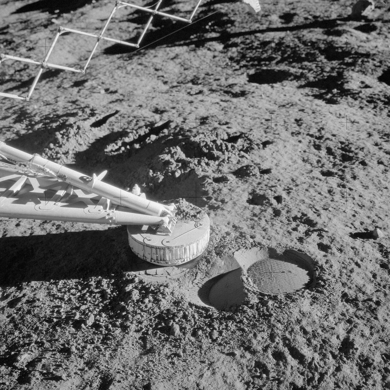 NASA. Public domain (NASA / US government work).
The problem
Section titled “The problem”A lander arm that tests soil has to act on a surface of unknown strength with a mechanism whose loads can be reconstructed, from a fixed base, through a command link that allows one motion at a time followed by a television picture. The environment adds no atmosphere to carry heat and a lunar night that the hardware must survive or be lost [9], [10]. Before Surveyor, strength estimates were passive: footpad penetration, crushable block imprints and the tracks of rolling fragments [11], plus optical, thermal, radio and radar inference of a low-density, highly porous surface of under 1 g/cm3 that Surveyor 1 footpad data and television particle counts overturned [11], [8].
What has flown
Section titled “What has flown”The Soil Mechanics Surface Sampler was a motorized scoop on an extending arm, flown on Surveyor 3 and Surveyor 7 and operated successfully on both [3], [10]. The program flew five successful landers between June 1966 and January 1968, and only these two carried the sampler; Surveyor 4 was lost before landing [3], [12], [13].
Surveyor 3 (20 April 1967). The lander came to rest tilted 12.5 degrees in the southeast of Oceanus Procellarum, a mare site [3]. The sampler ran for 18 h 22 min and performed 8 bearing tests, 14 impact tests, 4 trenches and the handling and dumping of material onto a footpad [9]. The touchdown telemetry anomaly invalidated the motor-current channel, so television was the only source and forces were bounded by deliberately stalling motors against preflight calibration [11]. The spacecraft never responded after its first lunar night, with compartments cooled to 0 F.
Surveyor 7 (10 January 1968). The lander sat on the ejecta blanket north of Tycho, in the southern highlands [10]. The mechanism was identical to the Surveyor 3 unit except for two horseshoe magnets in the scoop door bearing plate, a 30 degree rotation of the mounting, and an interface that let the sampler pick up the deployed alpha-scattering sensor head [3]. The current was sampled at a much higher rate across several commutator frames, which resolved the current pulse and gave a more accurate force [10]. The motors operated normally from 180 F down to minus 167 F after sunset, and the mechanism survived a lunar night across two lunar days. When the alpha-scattering head jammed in its background position, the sampler released it and relocated it to a rock and later to subsurface material, the first recovery of a failed instrument deployment by a robotic arm on another world. A rock was weighed at a density between 2.4 and 3.1 g/cm3 and another was broken by a moderately hard blow [10].
Specifications.
| Parameter | Value | Source |
|---|---|---|
| Configuration | scoop on a lazy-tongs extendable linkage with elevation, azimuth, extension and door axes, each driven by a small DC motor commanded by timed pulses | [3] |
| Tong extension | 64 in (1.63 m) with 54 degrees of vertical and 112 degrees of azimuth motion, as reported for Surveyor 3; 148 cm on the Surveyor 7 calibration | [9], [10] |
| Mass | 20.05 lb on Surveyor 3, 21.20 lb on Surveyor 7 | [3] |
| Force measurement | none fitted; applied force recovered from motor current | [3], [10] |
| Position measurement | position potentiometers, strain gages and accelerometers deleted | [3] |
The force-measuring instruments and potentiometers were deleted so that the sampler could replace the approach television camera on an unmodified spacecraft; two flight units were authorized in August 1966 and a spare was added to Surveyor VII in May 1967 [3]. The Hughes-built unit had no onboard computation: motion used timed motor pulses, a single motion needed several commands, and television could not be taken while the arm moved [3], [9], [10]. The two reach figures differ, 1.63 m against 1.48 m, and the sources do not reconcile them [9], [10].
Later lunar samplers and soil probes. The Apollo crews used a self-recording penetrometer, core tubes, a drill and the Lunar Roving Vehicle as soil probes, and the S-200 synthesis from those data replaced the Surveyor values as the reference model [5], [6]. Apollo 15 track depth averaged about 1.25 cm at a wheel load of about 290 N, and a trafficability parameter set with 35 degree friction reproduced measured rover energy consumption on Apollo 15, 16 and 17 [5], [6]. Chang’e-5 and Chang’e-6 scooped and returned samples with a four-degree-of-freedom arm [17], [18]. Lunar PlanetVac, a pneumatic sampler, acquired regolith on the Firefly Blue Ghost lander at Mare Crisium on 3 March 2025 in a five-second sequence, and the head sat in an off-nominal position [14], [15]. Yutu-2 gave the first rover-derived terramechanical characterization of farside regolith in 2024 [26].
What is being tried now
Section titled “What is being tried now”Soil properties from returned and in situ material (flown, analyzed on the ground). The Chang’e-6 scooped farside regolith has D60 of 48.4 um, volume-averaged sphericity of 0.58 against 0.69 for Apollo 11 and 14, and static and dynamic angles of repose of 52.9 and 70.4 degrees, above any Chang’e-5 or Apollo simulant measured, so it is markedly more cohesive than nearside soil [16]. Physical, mineralogical and geochemical characterization of those samples was compared against Chang’e-5 and Apollo material [18]. From the Yutu-2 wheel tracks, sinkage averaged about 8 mm, bearing capacity was near 4 kPa against 2 to 3 kPa along the Lunokhod-1 traverse, and cohesion was 520 to 3154 Pa with friction angle 21.5 to 42.0 degrees [26]. These replace an inference from one scoop with inversions from wheel motion and returned grains.
Autonomous sampling (flown). Chang’e-6 scooping selected sample points from a binocular point cloud against slope, relief and obstacle criteria, and replaced the manual fine-tuning used on Chang’e-5 with a 6D pose estimate by point cloud registration [17]. The four-degree-of-freedom arm alone had about 30 mm and 2 degrees of absolute end-effector error from flexible deformation, and soil sink under the touching disc of 5 to 20 mm was compensated separately [17]. Surveyor had no such loop: every step was an Earth-evaluated television picture [10].
Dedicated in situ strength instruments (ground test). The SPARTA toolkit combines a vane shear tester, cone penetrometer, thermal conductivity probe and dielectric probe, and has completed three phases of testing [22]. It fills the role the Surveyor sampler filled by improvisation, with force measured directly.
Strength in reduced gravity (ground test). Static cone penetration at 1/6 g, 1 g and 2 g on a magnetic levitation rig found that resistance at 1/6 g is about 29.1 percent below 1 g at 40 percent relative density but only about 8.8 percent below at 76 percent, so the lunar reduction at depth is likely smaller than assumed [19]. A drop tower shear and compression cell was built to obtain cohesion, friction angle and tensile strength at lunar and small-body acceleration [20]. Granular flow in a drop tower jammed at 0.19 g where it flowed freely at 1 g, because cohesion becomes comparable to weight [32]. Gravity offload by mass reduction gives overoptimistic trafficability because the grains are still under Earth gravity, and single-wheel drawbar pull measured in parabolic flight shows reduced-weight testing overstates mobility [33].
Simulants and databases (ground test). Cohesion of simulants grows exponentially with bulk density and spans 0.185 to 1.672 kPa for lunar types [21]. Particle size distribution alone does not set fidelity: simulants within one standard deviation of the lunar average differ substantially in shear strength, and the selected Mines testbed simulant has cohesion about 355 percent above the highland estimate [23]. NASA’s guide scores fourteen simulants and concludes no simulant reproduces every aspect of lunar regolith [24]. An open database consolidates lunar and simulant properties by measurement method [25]. Facility simulants are characterized for abrasion and density [29], a dust-suppressed cohesive simulant exists [31], and a DEM scaling study of a grousered wheel in FJS-1 simulant targets slip, sinkage and power at lunar gravity from Earth-gravity runs [30].
Simulation and gravity scaling (ground test). A smoothed-particle continuum model inside the Chrono multibody simulator reproduces discrete-element and physical single-wheel tractive force and torque curves at lower cost and was applied to a six-wheel Yutu model under lunar gravity [28]. Vertical vibration kept lunar simulant flowing through hoppers at lunar gravity in vacuum across 60 parabolas, where it otherwise arches and stops [34]. None of these has flown. The same boulder-track bearing technique that Apollo used has been applied to asteroid Didymos, giving a mean bearing capacity of 70 N/m2 [27].
The numbers
Section titled “The numbers”Surveyor bearing strength profile.
| Depth | Bearing strength | Evidence | Source |
|---|---|---|---|
| Uppermost millimeter | less than 0.1 N/cm2 | imprints of small rolling fragments | [11] |
| 1 to 2 mm | 0.2 N/cm2 | alpha-scattering sensor head imprint | [11] |
| 1 to 2 cm | 1.8 N/cm2 | crushable block imprints | [11] |
| averaged to 6 cm | 4 to 6 N/cm2 | footpad penetration | [11] |
Strength rises by nearly two orders of magnitude in the first few centimeters [11]. Footpad-derived static bearing strength at the Surveyor 7 site averaged 3.4 N/cm2, similar to Surveyors 1, 3 and 5 [10].
Soil parameters by source.
| Quantity | Value | Source |
|---|---|---|
| Surveyor cohesion | 0.035 to 0.05 N/cm2 | [11] |
| Surveyor friction angle | 35 to 37 degrees | [11] |
| Surveyor density | about 1.5 g/cm3, porosity 0.4 to 0.5 | [11] |
| Surveyor 7 Tycho soil | 37 to 39 degrees friction, about 1.5 g/cm3 | [10] |
| Apollo density, 0 to 15 cm | 1.50 g/cm3 | [6] |
| Apollo density, 30 to 60 cm | 1.74 g/cm3 | [6] |
| Apollo friction angle | 35 to 50 degrees | [6] |
| Apollo cohesion | 0.1 to 1.0 kN/m2 | [6] |
| Reference shear, 0 to 15 cm | 42 degrees, 0.52 kPa | [24] |
| Reference shear, 30 to 60 cm | 54 degrees, 3.0 kPa | [24] |
| Compiled database range | density 0.7 to 2.3 g/cm3, friction 20 to 55 degrees, cohesion up to about 5 kPa | [25] |
| Yutu-2 cohesion | 520 to 3154 Pa | [26] |
Surface debris from lander television was fitted to cumulative particle counts from 1 mm to 10 cm and beyond, with a stated factor of two on K and 0.2 on the exponent, fits made by eye to preliminary data [8]. The surface at 45 degrees latitude runs from a mean of 350 K at noon to 89 K before sunrise [2]. Mare and highland sites differ in failure mode rather than strength: Surveyor 3 soil cracked into relatively large chunks, Surveyor 7 material was more deformable and less brittle, and soil depth near Surveyor 7 varied from 1 to at least several inches over rock [10], [11].
What is not established
Section titled “What is not established”The Surveyor 3 forces rest on image interpretation and stall calibration, not on a recorded current history, and the program report presents bearing and cohesion values as brackets rather than values with uncertainties [9], [11]. Every Surveyor number is inferred from an action not designed as a soil test, so it carries the assumptions of its reduction model [11]. Reach figures are not reconciled. The Apollo model’s density and porosity conversions rest on few specific-gravity and void-ratio measurements and its trafficability parameters were fitted to energy consumption, so agreement with Surveyor is a consistency check, not a validation [6]. Farside soil is more cohesive than any nearside sample, so the nearside values do not transfer [16], [26]. The reduced-gravity effect on strength depends on relative density and is not settled for the lunar subsurface [19]. All in situ data are from equatorial and mid-latitude sites; polar regolith strength has no in situ reference measurement.
References
Section titled “References”References
- Heiken, G. H., Vaniman, D. T. and French, B. M. (1991). Lunar Sourcebook: A User's Guide to the Moon
. Endeavour. Source
BibTeX
@book{heiken1991lunar, title = {Lunar Sourcebook: A User's Guide to the Moon}, author = {Heiken, Grant H. and Vaniman, David T. and French, Bevan M.}, journal = {Endeavour}, volume = {16}, pages = {96}, publisher = {Cambridge University Press}, year = {1991}, doi = {10.1016/0160-9327(92)90014-g} } - Jet Propulsion Laboratory. (1969). Surveyor Project Final Report, Part 1: Project Description and Performance
. Jet Propulsion Laboratory, NASA-CR-105302. Source
BibTeX
@techreport{jpl1969surveyor, title = {Surveyor Project Final Report, Part 1: Project Description and Performance}, author = {{Jet Propulsion Laboratory}}, number = {NASA-CR-105302}, institution = {Jet Propulsion Laboratory}, year = {1969}, url = {https://ntrs.nasa.gov/citations/19690026375}, abstract = {The <i>Surveyor</i> Project planned and conducted seven unmanned lunar missions for which spacecraft were launched between May 1966 and January 1968. Each of the spacecraft was successfully launched with the then newly developed <i>Atlas/Centaur</i> vehicle which utilized for the first time a high-specific-impulse, liquid hydrogen/liquid oxygen fueled stage. Five of the spacecraft successfully soft-landed and returned a great quantity of engineering and scientific data on extensive postlanding operations, accomplishing all mission and project objectives. Four of the spacecraft soft-landed at selected mare sites to provide data which were required to support the <i>Apollo</i> Program. The final spacecraft was then successfully used for scientific investigation of a contrasting site in the rugged lunar highlands. <i>Surveyor</i> was a fully attitude-stabilized spacecraft designed to receive and execute a wide variety of earth commands, as well as to perform certain automatic functions including the critical terminal-descent and soft-landing sequences. Significant new and advanced subsystems that were developed and/or used in combination to enable <i>Surveyor</i> to execute the complex terminal phase of flight were: (1) a solid-propellant main retro motor, (2) throttlable liquid-propellant vernier engines (also used for midcourse velocity correction), (3) highly sensitive velocity- and altitude-sensing radars, and (4) an automatic closed-loop guidance and control system. The first <i>Surveyor</i> spacecraft carried a survey television camera which, together with other engineering instrumentation, obtained in-flight and postlanding data. The complement of instruments carried on later missions included various combinations of the following additional devices: (1) a soil mechanics/surface sampler instrument for picking, digging, and handling lunar surface material; (2) an alpha scattering instrument for performing a chemical analysis of the lunar surface material; and (3) magnets attached to the spacecraft for determining magnetic properties of the soil.} } - Mitchell, J. K., Bromwell, L. G., Carrier, W. D. I., Costes, N. C., Houston, W. N. and Scott, R. F. (1972). Soil mechanics experiment
. NASA, 19720015171. Source
BibTeX
@techreport{mitchell1972soil, title = {Soil mechanics experiment}, author = {Mitchell, James K. and Bromwell, L. G. and Carrier, W. D., III and Costes, Nicholas C. and Houston, William N. and Scott, Ronald F.}, number = {19720015171}, institution = {NASA}, year = {1972}, url = {https://ntrs.nasa.gov/citations/19720015171}, abstract = {The Apollo 15 soil-mechanics experiment has offered greater opportunity for study of the mechanical properties of the lunar soil than previous missions, not only because of the extended lunar-surface stay time and enhanced mobility provided by the lunar roving vehicle (rover), but also because four new data sources were available for the first time. These sources were: (1) the self-recording penetrometer (SRP), (2) new, larger diameter, thin-walled core tubes, (3) the rover, and (4) the Apollo lunar-surface drill (ALSD). These data sources have provided the best bases for quantitative analyses thus far available in the Apollo Program.} } - Mitchell, J. K., Carrier, W. D. I., Costes, N. C., Houston, W. N., Scott, R. F. and Hovland, H. J. (1974). Apollo soil mechanics experiment S-200
. NASA, NASA-CR-134306. Source
BibTeX
@techreport{mitchell1974apollo, title = {Apollo soil mechanics experiment S-200}, author = {Mitchell, James K. and Carrier, W. D., III and Costes, Nicholas C. and Houston, William N. and Scott, Ronald F. and Hovland, H. John}, number = {NASA-CR-134306}, institution = {NASA}, year = {1974}, url = {https://ntrs.nasa.gov/citations/19740019219}, abstract = {The physical and mechanical properties of the unconsolidated lunar surface material samples that were obtained during the Apollo missions were studied. Sources of data useful for deduction of soil information, and methods used to obtained the data are indicated. A model for lunar soil behavior is described which considers soil characteristics, density and porosity, strength, compressibility, and trafficability parameters. Lunar history and processes are considered, and a comparison is made of lunar and terrestrial soil behavior. The impact of the findings on future exploration and development of the moon are discussed, and publications resulting from lunar research by the soil mechanics team members are listed.} } - Shoemaker, E. M. and Morris, E. C. (1968). Size-Frequency Distribution of Fragmental Debris
. Surveyor Project Final Report, Part 2: Science Results, JPL Technical Report 32-1265. Source
BibTeX
@incollection{shoemaker1968size, title = {Size-Frequency Distribution of Fragmental Debris}, author = {Shoemaker, E. M. and Morris, E. C.}, booktitle = {Surveyor Project Final Report, Part 2: Science Results}, number = {JPL Technical Report 32-1265}, pages = {86--101}, institution = {Jet Propulsion Laboratory}, chapter = {III}, year = {1968}, url = {https://ntrs.nasa.gov/citations/19690019967}, abstract = {This two-part document constitutes the Project Final Report on the Surveyor spacecraft. Part I of this Technical Report consists of a technical description and an evaluation of engineering results of the systems used on Surveyor. Part II presents the science data derived from the lunar soft-landing missions, and the scientific analyses conducted by the Surveyor Scientific Evaluation Advisory Team, the Surveyor Investigator Teams, and the associated Working Croups. Results given in this part of this Technical Report are based on data evaluation before June 15, 1968. It is expected that future evaluations and analyses will provide additional science results.} } - Surveyor Investigator Teams. (1967). Surveyor III Mission Report, Part II: Scientific Results
. Jet Propulsion Laboratory, NASA-CR-88952. Source
BibTeX
@techreport{surveyor1967surveyor, title = {Surveyor III Mission Report, Part II: Scientific Results}, author = {{Surveyor Investigator Teams}}, number = {NASA-CR-88952}, institution = {Jet Propulsion Laboratory}, year = {1967}, url = {https://ntrs.nasa.gov/citations/19670028832}, abstract = {Television observations, soil sampling, lunar surface mechanical properties, lunar temperature and thermal characteristics, and other scientific results from Surveyor III mission} } - Surveyor Investigator Teams. (1968). Surveyor VII Mission Report, Part II: Science Results
. Jet Propulsion Laboratory, NASA-CR-97347. Source
BibTeX
@techreport{surveyor1968surveyor, title = {Surveyor VII Mission Report, Part II: Science Results}, author = {{Surveyor Investigator Teams}}, number = {NASA-CR-97347}, institution = {Jet Propulsion Laboratory}, year = {1968}, url = {https://ntrs.nasa.gov/citations/19680028774}, abstract = {Chemical analysis of rocks and soil and other scientific results obtained for Tycho landing site by Surveyor 7 lunar probe} } - Surveyor Scientific Evaluation Advisory Team. (1968). Surveyor Project Final Report, Part 2: Science Results
. Jet Propulsion Laboratory, NASA-CR-101584. Source
BibTeX
@techreport{surveyor1968surveyorb, title = {Surveyor Project Final Report, Part 2: Science Results}, author = {{Surveyor Scientific Evaluation Advisory Team}}, number = {NASA-CR-101584}, institution = {Jet Propulsion Laboratory}, year = {1968}, url = {https://ntrs.nasa.gov/citations/19690019967} } - (2017). NASA: Surveyor 3. science.nasa.gov/mission/surveyor-3
BibTeX
@misc{nasasurveyor, title = {NASA: Surveyor 3}, organization = {science.nasa.gov}, year = {2017}, url = {https://science.nasa.gov/mission/surveyor-3/} } - (2017). NASA: Surveyor 7. science.nasa.gov/mission/surveyor-7
BibTeX
@misc{nasasurveyor2,
  title = {NASA: Surveyor 7},
  organization = {science.nasa.gov},
  year = {2017},
  url = {https://science.nasa.gov/mission/surveyor-7/}
}
Further reading
- Costes, N. C., Farmer, J. E. and George, E. B. (1972). Mobility Performance of the Lunar Roving Vehicle: Terrestrial Studies --- Apollo 15 Results . Conference of the International. Source
- Mitchell, J. K., Houston, W. N., Scott, R. F., Costes, N. C., Carrier, W. D. and Bromwell, L. G. (1972). Mechanical properties of lunar soil: Density, porosity, cohesion, and angle of internal friction . Lunar Science Conference. Source
- NASA. (1969). Apollo 11 Preliminary Science Report . NASA Manned Spacecraft Center. Source