NASA LaRC Landing and Impact Research Facility
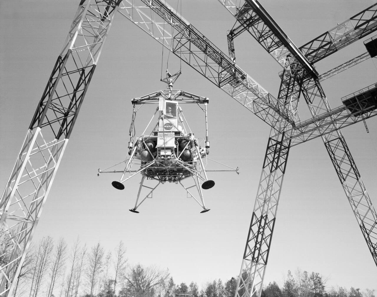
NASA Bob Nye. Public domain (NASA / US government work).
A 240 ft steel A-frame gantry at NASA LaRC, built in 1965 as the Lunar Landing Research Facility to fly Apollo crews through the last 150 ft of a lunar descent under a suspension carrying five sixths of the vehicle weight, converted at the end of Apollo into a full-scale aircraft crash test facility, and now the Landing and Impact Research Facility used for spacecraft landing attenuation, airframe crashworthiness and water impact [1][3].
Laboratory data
Section titled “Laboratory data”| Parameter | Value |
|---|---|
| Operator | NASA LaRC, Research Directorate [1][6] |
| Location | Hampton, Virginia, United States [1] |
| Commissioned | Gantry completed 1965; hydro impact basin added 2011 [1][6] |
| Type | Outdoor A-frame gantry, water impact basin and four drop towers |
| Floor area | Impact strip 121 x 9.0 m; basin 35 x 27 m [2][6] |
| Capabilities | Gantry, Hydro Impact Basin, drop towers [6] |
| Simulant or terrain | No simulant. Reinforced concrete strip and an adjacent soft soil area [1][2] |
| Instrumentation | Photogrammetry: Phantom 9 cameras, 1000 fps at 1632 x 1200 [3][6] |
| Ground truth | Painted 1.0 m grid on the strip; 30 x 12 m gridded backboard on rails [2] |
| Fidelity limits | Pitch angle accuracy 4.25 degrees; uncompensated umbilical moment |
| Access | Named point of contact; no fee schedule or lead time published [6] |
| Cited by | Apollo Lunar Module descent training [1], Orion landing attenuation [3][5] |
Capabilities
Section titled “Capabilities”Gantry
Section titled “Gantry”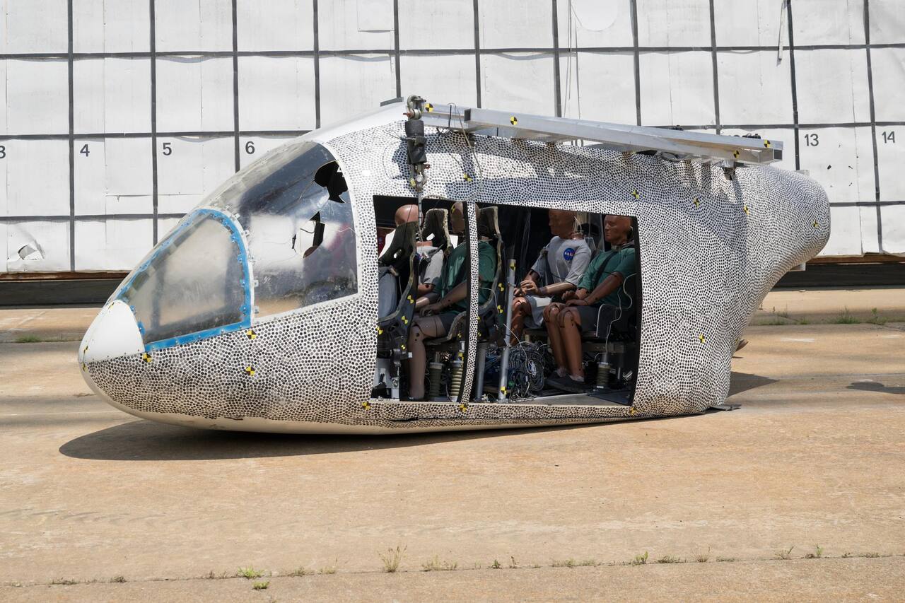
NASA Mark Knopp. Public domain (NASA / US government work).
| Parameter | Value |
|---|---|
| Working volume | 240 ft (73 m) high, 400 ft (122 m) long, 265 ft (81 m) wide at the base [1][6] |
| Test article limits | Maximum bridge crane load 65,000 lb (29,500 kg) [6] |
| Vacuum | Not applicable. Outdoor structure at ambient pressure |
| Temperature | Not applicable. No thermal control; Virginia outdoor conditions |
| Illumination | Not published. Historic LLRF tests were run at night |
| Simulant or terrain | Reinforced concrete strip 121 x 9.0 m, 0.2 m thick, plus a soft soil area [1][2] |
| Slope | Not applicable. The impact surface is level |
| Gravity offload | Not offered. The historic 5/6 suspension is not a current capability [6] |
| Instrumentation | Phantom 9 cameras, 1000 fps at 1632 x 1200, on 24 mm lenses [3] |
The gantry is a steel A-frame of truss elements with three sets of inclined legs giving vertical and lateral support and one set at the east end giving longitudinal support, with legs 81 m apart at the ground narrowing to 20 m apart at the 66 m level, where a movable bridge traverses the full length [1][2][6]. An enclosed elevator, a stairway and catwalks give access to the overhead work platforms [1][2][6]. Maximum drop height is approximately 200 ft (61 m).
Impact conditions are set independently of article mass: flight path angles to -60 degrees from swing cable length, suspension height to a 49 m maximum giving impact velocity along the flight path up to 27 m/s, and up to about 30 degrees in angle of attack and roll from suspension cable lengths, with only small yaw adjustment possible because of clearance between the pullback harness and the empennage [2]. Achieved accuracy is flight path within 8 percent, velocity within 6 percent and pitch angle to 4.25 degrees [2].
The operator’s current article figure is a maximum bridge crane load of 65,000 lb (29,500 kg), which supersedes the 30,000 lb (13,600 kg) article limit given in the 2013 history [6]. The original cable systems were operated with aircraft of 2721 kg nominal gross mass at a 2 g dynamic swing load; with block and tackle cable arrangements to reduce winch forces, the system could crash test aircraft to 14,000 kg gross mass [1][2][6].
The historic partial-gravity suspension is not part of the current capability. It supported five sixths of the total weight of the Lunar Excursion Module Simulator, leaving one sixth on the vehicle’s own thrusters, so that crews flew the last 150 ft of a lunar descent in a dynamically correct gravity field [1]. NASA now describes that arrangement only in the past tense, and it appears in neither the operator’s current Gantry Key Features nor its Other Facility Equipment list; whether the hardware was physically removed is not published [1][2][6].
Hydro Impact Basin
Section titled “Hydro Impact Basin”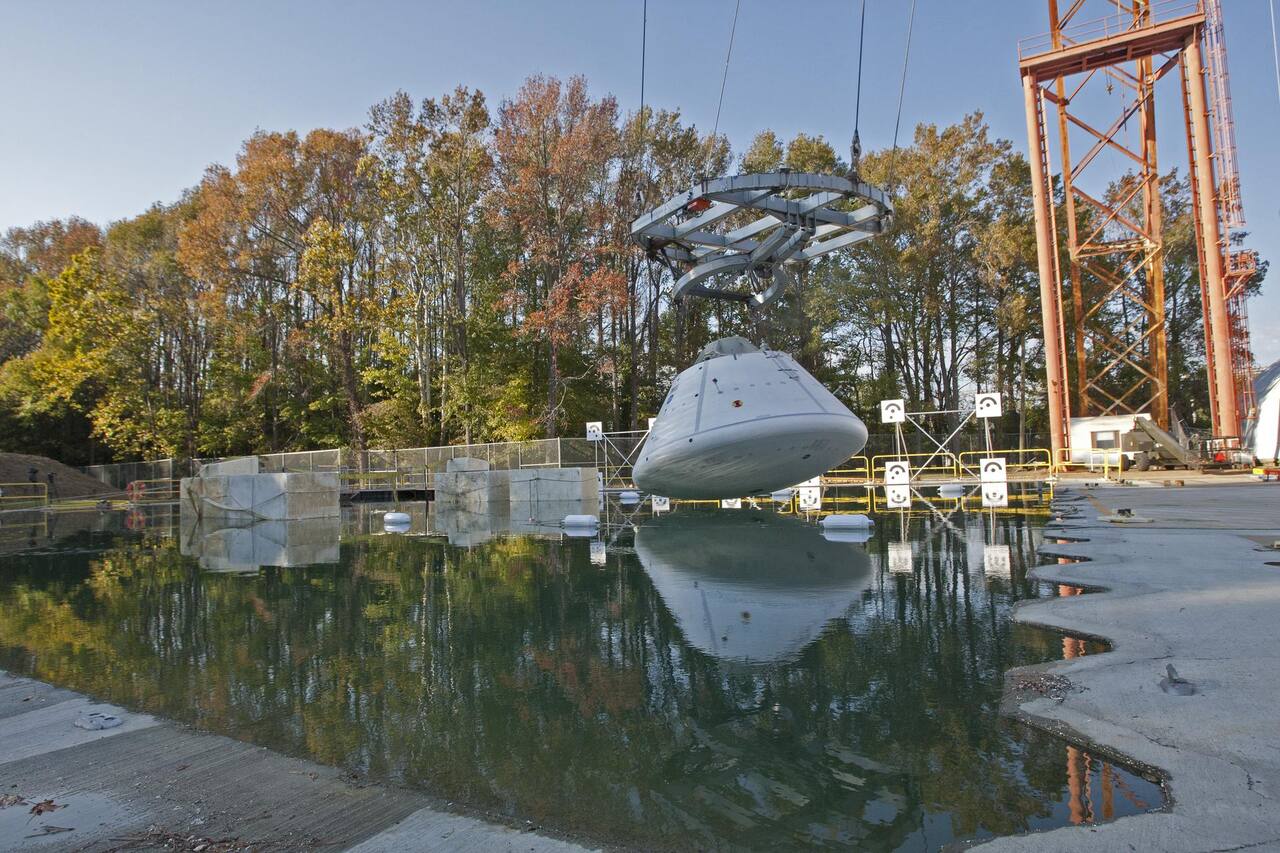
Sean Smith. Public domain (NASA / US government work).
| Parameter | Value |
|---|---|
| Working volume | 115 x 90 x 20 ft deep (35 x 27 x 6 m) [6] |
| Test article limits | Shares the gantry’s 65,000 lb maximum bridge crane load |
| Simulant or terrain | Water |
| Gravity offload | Not offered. Articles are released into free flight at 1 g |
| Instrumentation | Shared photogrammetry and data acquisition [3][6] |
The basin was added in 2011 at the west end of the gantry and is where the water landing tests are run [6]. Orion crew vehicle water landings, and land impact testing of the capsule that will return Mars samples to Earth, have been run at the complex.
Drop towers
Section titled “Drop towers”| Parameter | Value |
|---|---|
| Working volume | 72 ft outdoor; 50 ft three-rail outdoor; 30 ft four-rail and 15 ft two-rail indoor [6] |
| Instrumentation | Portable photogrammetric backboard, 16 coded targets in a 10 x 6 ft array [3] |
Four towers cover the vertical-only drops that do not need the gantry’s pendulum swing: a 72 ft outdoor tower, a 50 ft three-rail outdoor tower, a 30 ft four-rail indoor tower and a 15 ft two-rail indoor tower [6]. The portable rolling calibration backboard was built for vertical drops under the 70 ft tower [3].
The operator’s current instrumentation list for the complex is anthropomorphic test devices, materials testing machines, high-speed cameras, ruggedized data acquisition systems, three-dimensional scanners, accelerometers, load cells and string potentiometers.
How a swing test is run
Section titled “How a swing test is run”In its original configuration the facility was a partial-gravity flight trainer: the suspension supported five sixths of the total weight of the Lunar Excursion Module Simulator, so that the vehicle’s own thrusters worked against the remaining one sixth and the pilot flew the last 150 ft of a lunar descent in a dynamically correct gravity field [1]. The ground beneath the gantry was reshaped to resemble lunar terrain, and many tests were run at night to reproduce the lighting of the actual landing [1].
After Apollo the same structure became a crash test facility. Two pivot-point platforms at the west end carry 26.7 kN winches and sheave systems controlling swing cable length, with cable locks protecting the winches from overload and dynamic reaction; a pullback platform under the movable bridge carries a third 26.7 kN winch for the pullback cable, and the bridge is positioned so that the pullback and swing cables meet at the required 90 degrees [2].
The test sequence is three pyrotechnic events. The article, suspended on two swing cables and drawn back and up by the pullback cable, is released from the pullback harness and swings pendulum style toward the impact surface; the swing cables are pyrotechnically separated a short distance above the surface so that the article is completely unrestrained through the impact; and the umbilical cable is separated at a predetermined time after swing-cable separation, during the post-impact skid [1][2]. Flight path angle up to -60 degrees comes from swing cable length; velocity along the flight path, up to 27 m/s, comes from the 49 m maximum suspension height.
The suspension geometry is set so that the swing and pullback cable force vectors both pass through the article’s center of gravity, leaving it free to pitch about its own center of gravity, with two sets of pitch cables restraining the planned angle of attack during preparation and swing. A 0.76 cm steel support cable is sandwiched into the umbilical wiring to carry load and protect the data wires from unintended tensile loads; it passes through the top of the fuselage and attaches to the main spar near the center of gravity, while the data wires connect 1.1 m above the center of gravity [2].
The impact surface is the reinforced concrete strip, with a painted 1.0 m grid, backed by a 30 m by 12 m gridded photographic backboard on rails so it can be moved to whichever point along the strip a test uses [1][2]. A soft soil area exists alongside, and impact surface was a standard test variable in the general aviation crash program [1][2].
Instrumentation
Section titled “Instrumentation”Measurement at the facility is photogrammetric rather than contact-based wherever possible. The high-speed cameras are Phantom 9 units run at 1000 frames per second at the full 1632 x 1200 sensor [3]. Swing tests use 24 mm lenses with the cameras at least 50 ft from the test article and 80 to 90 ft from the calibration backboard, focused at infinity so that article and backboard are both sharp, which gives a calibrated volume of roughly 62 ft wide by 45 ft tall and more than 30 ft deep.
Calibration is the part that outdoor work at this scale changes. Handheld panels are useless over a 50 ft field, so the facility uses two custom objects instead: a large fixed backboard with 24 coded targets in a 50 x 36 ft array for gantry swing tests, and a portable backboard on rollers with 16 coded targets in a 10 x 6 ft array for vertical drops under the 70 ft tower [3]. The backboard is held still and the cameras are moved, 16 to 25 images each, from as much as 40 degrees off axis and 30 to 120 ft away. Sunlight is the dominant nuisance: sharp contrast and hard shadows defeat the software’s target recognition, so images are artificially flattened on bright days and camera settings held identical between calibration and test [3].
Some targets on the backboard are left inside the test field of view and reused for the coordinate reference frame. Because the backboard does not move, the residual displacement the software computes for its targets is the measurement noise: about plus or minus 0.05 in, a 0.10 in range across a 62 ft field, or 0.01 percent [3]. Vehicle pitch, yaw and roll are recovered as projection angles between lines drawn on the vehicle and lines on the backboard, and differentiated for angular rates at impact. Every camera and data system is tied to an IRIG-B time code generator so that otherwise incompatible systems share one time stamp [3].
The same photogrammetric approach was applied to crew exploration vehicle airbag landing attenuation systems, measuring the deforming airbag and the capsule together during impact [5].
What it does not reproduce
Section titled “What it does not reproduce”Pitch, exactly. The swing cable catenary introduces pitch error into the system, and the pitching velocity of the article at swing cable separation is a consequence of it [2]. Published accuracy is flight path within 8 percent, velocity within 6 percent, and pitch angle to 4.25 degrees [2]. The pitch figure is an absolute angle, not a percentage, and is the loosest of the three.
The umbilical. The mass of the umbilical acting 1.1 m above the article’s center of gravity creates a pitching moment that varies with drag on the umbilical, and it is not compensated for during the swing phase [2]. Analytical predictions of the swing do not consider aerodynamic forces after swing-cable separation nor catenary effects [2].
Yaw. Only small yaw adjustments are possible because of the clearance between the pullback harness and the article’s empennage. Additional yaw requires removing the stabilizers and simulating them with concentrated masses, which changes the structure being tested [2].
Velocity above the pendulum limit. The 27 m/s ceiling set by the 49 m suspension height was sufficient for the take-off and landing speeds of small general aviation aircraft, 81 to 88 fps, but not for the larger pressurized aircraft tested in the early 1980s, for which a Velocity Augmentation System using rockets had to be added [1].
Article mass. The operator’s current figure is a 65,000 lb maximum bridge crane load [6]; the 2013 history gives an article limit of 30,000 lb or less [1]. The original cable systems were rated for a 2721 kg article at a 2 g dynamic swing load, extended to 14,000 kg only with block and tackle arrangements to reduce winch forces [2].
Gravity, except in the original configuration. The five sixths weight relief that made the LLRF a lunar simulator applied to a tethered vehicle in powered descent, and it relieved five sixths of Earth weight rather than producing five sixths of lunar gravity [1]. It is not offered today: NASA writes about it only in the past tense and lists it among neither the gantry’s key features nor its other facility equipment [6]. A crash test article in free flight after swing-cable separation is at 1 g, and impact accelerations measured on the concrete or the soil are terrestrial.
Soil. The soft soil area is terrestrial soil, not a regolith simulant, and its preparation is not described in the facility literature [1][2]. Soft soil impacts were run specifically to study modifications that would let an aircraft skid along the surface rather than decelerate longitudinally [1], which is a crashworthiness question rather than a terramechanics one.
Campaigns run there
Section titled “Campaigns run there”Apollo Lunar Module descent training, 1965 to end of Apollo. Crews flew a Lunar Excursion Module Simulator tethered to the gantry through the final 150 ft of descent, at five sixths weight relief, over a reshaped lunar-looking surface, frequently at night [1].
General aviation crash test program, 1974 to 1983. Thirty-three full-scale crash tests in ten years [1]. Test articles were mostly Piper Aztecs and Cherokees obtained for scrap aluminum value because they had been submerged in a flood at the Piper plant and could not be certified, retrofitted or sold; later tests used Cessna 172s and larger pressurized Piper Navajos [1]. Variables were impact velocity, airframe attitude at impact, and impact surface, hard or soft soil. The stated purpose was definitive data on structural response and on the loads transmitted to occupants, for correlation with analytical prediction and for evaluating crashworthy structure, seat and restraint concepts [1].
Rotorcraft crash testing. Helicopters are tested with lower forward and higher vertical velocity than fixed wing aircraft; the 1999 crash test of a Sikorsky prototype ran at 31.5 fps forward and 38 fps vertical, against 82 fps forward and 31 fps vertical for the 1994 Lear Fan 2100 test [1]. A series was conducted on both soft soil and concrete, and a further set on soft soil across a range of roll, pitch and yaw angles, on articles of nominal 9,000 lb gross weight including external fuel system, simulated fuel, swing fixture and instrumentation [1].
Orion and crew exploration vehicle landing, 2003 onward. The Constellation program ran five swing tests in the summer of 2009 on a 5146 lb, 8 ft diameter subscale Orion boilerplate into a 4 ft high by 20 ft wide by 78 ft long sand bed, varying vertical and horizontal velocity to assess abort land landing conditions; the sand bed obscured the bottom row of calibration targets and the cameras had to be tilted so the calibrated cube sat on the sand surface [3]. Water landing tests of the Orion crew vehicle, and land impact testing of the capsule that will return Mars samples to Earth, have since been run at the complex [6]. Photogrammetric measurement of airbag landing attenuation systems characterized airbag and capsule deformation through impact [5]. Numerical modeling of space capsule ground landings was correlated against the facility’s drop test data [4].
MD-500 helicopter crash test, 2009. A full-scale MD-500 mass simulator was swung into the impact surface and its conditions recovered photogrammetrically at 27.1 ft/s horizontal and 17.5 ft/s vertical with 1.8 degrees pitch, 6.7 degrees yaw and 3.4 degrees roll, against planned conditions of 28 ft/s horizontal, 18.2 ft/s vertical and zero attitude angles [3]. A later test in the series added a speckle pattern for full-field strain, which resolved a strain field on the tail skin but at an effective gauge length of about 6 in, too coarse to match a strain gauge rosette painted underneath it [3].
Current work. The complex is equipped for coupon through airframe testing with indoor and outdoor drop towers, anthropomorphic test devices, materials testing machines and three-dimensional scanners alongside the gantry [6].
Other ways landing and impact are tested
Section titled “Other ways landing and impact are tested”The Langley gantry reproduces impact at 1 g with a free-flying article [1][2]. Other facilities answer different parts of the landing question, and the differences set what each can and cannot say about a lander or rover.
Aircraft crash history. The facility’s crash programs from 1974 onward are surveyed separately from the history cited above, including helicopter qualification work, fuselage section drops, crew escape capsule drops and component work for the Mars Sample Return Earth Entry Vehicle [7].
Robot-held touchdown. DLR’s Landing and Mobility Test Facility in Bremen suspends the test object from a heavy-duty industrial robot on a linear rail through a weight offloading suspension, and used it for Philae landing gear touchdown testing [8]. The same facility dropped and dragged instrumented lander footpads onto prepared sand for a European lunar lander study [9], and has run drop tests of a preliminary model of the MMX rover [10]. The Philae work shows an offload rig contaminating the measurement it exists to make [8]. The robot approach controls release conditions more finely than the pendulum, at much smaller article mass.
Subscale dynamic similitude. JPL’s Mars Sample Return lander tests used a 3/8 scale article with length, acceleration and stress scaled by similitude, because a full-scale drop would need both a gravity offload and a very heavy article [16]. This trades fidelity of mass and velocity for feasibility, where Langley drops full-scale articles.
Airbag landing under Mars conditions. Mars Exploration Rover airbag loads were characterized in full-scale drops inside a vacuum chamber at Martian pressure, then turned into a qualification specification for a shaker rather than a centrifuge or pull tower [17][18]. Mars Pathfinder’s lander deployment actuators were qualified for the righting sequence after airbag landing [30]. Langley’s Orion airbag work measured the bag and capsule with photogrammetry in ambient air on soil [5].
Chinese landing test field. China reported hover and obstacle-avoidance tests of its first Mars lander at a Hebei test field with simulated Martian gravity [19], and a landing and take-off verification of the Lanyue crewed lander at the same field [20]. Both are press items; instrumentation and gravity method are not described in them.
Flight reconstruction of touchdown. On-orbit and surface data serve as the only full-fidelity check of ground landing tests. Philae’s four contacts with comet 67P were reconstructed from landing gear data, with a first-touchdown energy partly absorbed by the soil [21], and its rotational motion was fitted with a multibody model using solar panel power [22]. Huygens’ first seconds on Titan were reconstructed from accelerometry and photometry [23]. A rocket-borne flight test of terrain relative navigation with a Doppler lidar gave truth against DGPS for landing navigation rather than impact loads [29].
Small-body and low-gravity impact. Regolith response to slow contact changes with gravity level, as parabolic, shuttle and suborbital experiments showed [25]. Granular force laws fitted in laboratory gravity were extended numerically to a 1300 kg spacecraft pressing on asteroid regolith at about 10 cm/s [24], and a large crater from the Hayabusa2 impactor was reproduced only by simulation, since the regime cannot be reached on Earth [26]. A shear and compression cell built for drop tower falls measures regolith strength at small-body, lunar and Titan accelerations [27]. The Bremen drop tower supplies the free-fall time those experiments use [11]. The SLIM lunar lander’s results, with crushable porous metal shock absorbers, are reviewed by its project lead [28]. None of these reproduce an impact of a lander-class article on a hard surface at Earth gravity, which the gantry does.
Gravity offload for crew and rovers. The Langley suspension relieved five sixths of weight on a vehicle in powered descent [1]. Later offload systems target walking and manipulation instead. A pneumatic constant-force rig held reference lift to within 2.2 to 10 percent of command, degrading with the dynamic content of motion [12]. ARGOS offloads a suited subject with three active translational axes, and its fidelity depends on a gimbal pivot placed within a few centimeters of the combined center of gravity [13][14]. A student overhead trolley tracks a rover-mounted infrared beacon over a simulant sandbox [15].
Historical environment simulation. The Apollo-era vacuum chambers at Johnson Space Center, documented in a monograph, were built for thermal and vacuum work and not for landing dynamics [31].
What is not established
Section titled “What is not established”NASA Langley closed the Impact Dynamics Research Facility in September 2003 with demolition planned for 2007 [1]. The later Orion campaigns and the operator’s 2022 page show the gantry in use under the LandIR name [3][5][6]; the corpus holds no document describing the interval or what was refurbished, so whether the pre-2003 cable systems and instrumentation are the current ones is not established.
The gantry load figure differs by source: 64,000 lb (284.7 kN) in the 2009 Orion correlation paper [4] and 65,000 lb in the operator’s page [6]. Neither states the largest article that can be dropped under the swing arrangement, and the operator’s page gives a maximum drop height of about 200 ft without an achievable velocity, release-condition accuracy or calibration statement for its listed instruments [6].
The soil is characterized only as a sand and clay mixture standing in for a dry lakebed in the Orion airbag series [5]; its density, depth and reconditioning between drops are not given. The soil-vehicle friction coefficient of 0.45 is back-calculated by matching simulated to measured stopping distance, so it absorbs other modeling error [4]. The photogrammetric uncertainty (angle bias 0.06 degrees, 2-sigma precision 0.006 degrees) is derived from target pixel geometry and fit residuals rather than an independent reference [5]. No water basin wave, current or temperature capability is published [6].
References
- Jackson, K. E., Boitnott, R. L., Fasanella, E. L., Jones, L. E. and Lyle, K. H. (2004). A History of Full-Scale Aircraft and Rotorcraft Crash Testing and Simulation at NASA Langley Research Center
. Triennial International Aircraft and Cabin Safety Research Conference, 20040191337. Source
BibTeX
@inproceedings{jackson2004history, title = {A History of Full-Scale Aircraft and Rotorcraft Crash Testing and Simulation at NASA Langley Research Center}, author = {Jackson, Karen E. and Boitnott, Richard L. and Fasanella, Edwin L. and Jones, Lisa E. and Lyle, Karen H.}, booktitle = {Triennial International Aircraft and Cabin Safety Research Conference}, number = {20040191337}, institution = {NASA}, address = {Lisbon}, year = {2004}, url = {https://ntrs.nasa.gov/citations/20040191337}, abstract = {This paper summarizes 2-1/2 decades of full-scale aircraft and rotorcraft crash testing performed at the Impact Dynamics Research Facility (IDRF) located at NASA Langley Research Center in Hampton, Virginia. The IDRF is a 240-ft.-high steel gantry that was built originally as a lunar landing simulator facility in the early 1960's. It was converted into a full-scale crash test facility for light aircraft and rotorcraft in the early 1970 s. Since the first full-scale crash test was preformed in February 1974, the IDRF has been used to conduct: 41 full-scale crash tests of General Aviation (GA) aircraft including landmark studies to establish baseline crash performance data for metallic and composite GA aircraft; 11 full-scale crash tests of helicopters including crash qualification tests of the Bell and Sikorsky Advanced Composite Airframe Program (ACAP) prototypes; 48 Wire Strike Protection System (WSPS) qualification tests of Army helicopters; 3 vertical drop tests of Boeing 707 transport aircraft fuselage sections; and, 60+ crash tests of the F-111 crew escape module. For some of these tests, nonlinear transient dynamic codes were utilized to simulate the impact response of the airframe. These simulations were performed to evaluate the capabilities of the analytical tools, as well as to validate the models through test-analysis correlation. In September 2003, NASA Langley closed the IDRF facility and plans are underway to demolish it in 2007. Consequently, it is important to document the contributions made to improve the crashworthiness of light aircraft and rotorcraft achieved through full-scale crash testing and simulation at the IDRF.} } - Vaughan, V. L. J. and Alfaro-Bou, E. (1976). Impact dynamics research facility for full-scale aircraft crash testing
. NASA, NASA-TN-. Source
BibTeX
@techreport{vaughan1976impact, title = {Impact dynamics research facility for full-scale aircraft crash testing}, author = {Vaughan, V. L. J. and Alfaro-Bou, E.}, number = {NASA-TN-}, institution = {NASA}, year = {1976}, url = {https://ntrs.nasa.gov/citations/19760014085}, abstract = {An impact dynamics research facility (IDRF) was developed to crash test full-scale general aviation aircraft under free-flight test conditions. The aircraft are crashed into the impact surface as free bodies; a pendulum swing method is used to obtain desired flight paths and velocities. Flight paths up to -60 deg and aircraft velocities along the flight paths up to about 27.0 m/s can be obtained with a combination of swing-cable lengths and release heights made available by a large gantry. Seven twin engine, 2721-kg aircraft were successfully crash tested at the facility, and all systems functioned properly. Acquisition of data from signals generated by accelerometers on board the aircraft and from external and onboard camera coverage was successful in spite of the amount of damage which occurred during each crash. Test parameters at the IDRF are controllable with flight path angles accurate within 8 percent, aircraft velocity accurate within 6 percent, pitch angles accurate to 4.25 deg, and roll and yaw angles acceptable under wind velocities up to 4.5 m/s.} } - Littell, J. D. (2010). Large Field Photogrammetry Techniques in Aircraft and Spacecraft Impact Testing
. Society of Experimental Mechanics Annual Meeting, 20100024230. Source
BibTeX
@inproceedings{littell2010large, title = {Large Field Photogrammetry Techniques in Aircraft and Spacecraft Impact Testing}, author = {Littell, Justin D.}, booktitle = {Society of Experimental Mechanics Annual Meeting}, number = {20100024230}, pages = {55-67}, publisher = {Society for Experimental Mechanics}, institution = {NASA}, address = {Indianapolis, Indiana}, year = {2010}, doi = {10.1007/978-1-4419-8228-5_9}, abstract = {The Landing and Impact Research Facility (LandIR) at NASA Langley Research Center is a 240 ft. high A-frame structure which is used for full-scale crash testing of aircraft and rotorcraft vehicles. Because the LandIR provides a unique capability to introduce impact velocities in the forward and vertical directions, it is also serving as the facility for landing tests on full-scale and sub-scale Orion spacecraft mass simulators. Recently, a three-dimensional photogrammetry system was acquired to assist with the gathering of vehicle flight data before, throughout and after the impact. This data provides the basis for the post-test analysis and data reduction. Experimental setups for pendulum swing tests on vehicles having both forward and vertical velocities can extend to 50 x 50 x 50 foot cubes, while weather, vehicle geometry, and other constraints make each experimental setup unique to each test. This paper will discuss the specific calibration techniques for large fields of views, camera and lens selection, data processing, as well as best practice techniques learned from using the large field of view photogrammetry on a multitude of crash and landing test scenarios unique to the LandIR.} } - Heymsfield, E. and Fasanella, E. L. (2009). Using Numerical Modeling to Simulate Space Capsule Ground Landings
. Transportation Research Board Annual Meeting, 20090007688. Source
BibTeX
@inproceedings{heymsfield2009numerical, title = {Using Numerical Modeling to Simulate Space Capsule Ground Landings}, author = {Heymsfield, Ernie and Fasanella, Edwin L.}, booktitle = {Transportation Research Board Annual Meeting}, number = {20090007688}, institution = {NASA}, address = {Washington, DC}, year = {2009}, url = {https://ntrs.nasa.gov/citations/20090007688}, abstract = {Experimental work is being conducted at the National Aeronautics and Space Administration s (NASA) Langley Research Center (LaRC) to investigate ground landing capabilities of the Orion crew exploration vehicle (CEV). The Orion capsule is NASA s replacement for the Space Shuttle. The Orion capsule will service the International Space Station and be used for future space missions to the Moon and to Mars. To evaluate the feasibility of Orion ground landings, a series of capsule impact tests are being performed at the NASA Langley Landing and Impact Research Facility (LandIR). The experimental results derived at LandIR provide means to validate and calibrate nonlinear dynamic finite element models, which are also being developed during this study. Because of the high cost and time involvement intrinsic to full-scale testing, numerical simulations are favored over experimental work. Subsequent to a numerical model validated by actual test responses, impact simulations will be conducted to study multiple impact scenarios not practical to test. Twenty-one swing tests using the LandIR gantry were conducted during the June 07 through October 07 time period to evaluate the Orion s impact response. Results for two capsule initial pitch angles, 0deg and -15deg , along with their computer simulations using LS-DYNA are presented in this article. A soil-vehicle friction coefficient of 0.45 was determined by comparing the test stopping distance with computer simulations. In addition, soil modeling accuracy is presented by comparing vertical penetrometer impact tests with computer simulations for the soil model used during the swing tests.} } - Barrows, D. A., Burner, A. W., Berry, F. C., Dismond, H. R. and Cate, K. H. (2008). Photogrammetric Measurements of CEV Airbag Landing Attenuation Systems
. AIAA Aerospace Sciences Meeting, 20080008867. Source
BibTeX
@inproceedings{barrows2008photogrammetric, title = {Photogrammetric Measurements of CEV Airbag Landing Attenuation Systems}, author = {Barrows, Danny A. and Burner, Alpheus W. and Berry, Felecia C. and Dismond, Harriett R. and Cate, Kenneth H.}, booktitle = {AIAA Aerospace Sciences Meeting}, number = {20080008867}, institution = {NASA}, year = {2008}, doi = {10.2514/6.2008-846}, abstract = {High-speed photogrammetric measurements are being used to assess the impact dynamics of the Orion Crew Exploration Vehicle (CEV) for ground landing contingency upon return to earth. Test articles representative of the Orion capsule are dropped at the NASA Langley Landing and Impact Research (LandIR) Facility onto a sand/clay mixture representative of a dry lakebed from elevations as high as 62 feet (18.9 meters). Two different types of test articles have been evaluated: (1) half-scale metal shell models utilized to establish baseline impact dynamics and soil characterization, and (2) geometric full-scale drop models with shock-absorbing airbags which are being evaluated for their ability to cushion the impact of the Orion CEV with the earth s surface. This paper describes the application of the photogrammetric measurement technique and provides drop model trajectory and impact data that indicate the performance of the photogrammetric measurement system.} } - NASA Langley Research Center. (2022). Landing and Impact Research Facility (LandIR). researchdirectorate.larc.nasa.gov/landing-and-impact-research-facilit...
BibTeX
@misc{larc2022landir, title = {Landing and Impact Research Facility (LandIR)}, author = {{NASA Langley Research Center}}, organization = {researchdirectorate.larc.nasa.gov}, year = {2022}, url = {https://researchdirectorate.larc.nasa.gov/landing-and-impact-research-facility-landir/} } - Jackson, K. E. and Fasanella, E. L. (2003). A Survey of Research Performed at NASA Langley Research Center's Impact Dynamics Research Facility
. AIAA/ASME/ASCE/AHS/ASC Structures, Structural Dynamics, and Materials Conference, 20030032354. Source
BibTeX
@inproceedings{jackson2003survey, title = {A Survey of Research Performed at NASA Langley Research Center's Impact Dynamics Research Facility}, author = {Jackson, Karen E. and Fasanella, Edwin L.}, booktitle = {AIAA/ASME/ASCE/AHS/ASC Structures, Structural Dynamics, and Materials Conference}, number = {20030032354}, institution = {NASA}, year = {2003}, doi = {10.2514/6.2003-1896}, abstract = {The Impact Dynamics Research Facility (IDRF) is a 240-ft-high gantry structure located at NASA Langley Research Center in Hampton, Virginia. The facility was originally built in 1963 as a lunar landing simulator, allowing the Apollo astronauts to practice lunar landings under realistic conditions. The IDRF was designated a National Historic Landmark in 1985 based on its significant contributions to the Apollo Program. In 1972, the facility was converted to a full-scale crash test facility for light aircraft and rotorcraft. Since that time, the IDRF has been used to perform a wide variety of impact tests on full-scale aircraft and structural components in support of the General Aviation (GA) aircraft industry, the US Department of Defense, the rotorcraft industry, and NASA in-house aeronautics and space research programs. The objective of this paper is to describe most of the major full-scale crash test programs that were performed at this unique, world-class facility since 1974. The past research is divided into six sub-topics: the civil GA aircraft test program, transport aircraft test program, military test programs, space test programs, basic research, and crash modeling and simulation.} } - Schröder, S., Biele, J., Block, J., Roll, R., Ulamec, S. and Witte, L. (2013). Philae Landing Test at the Landing and Mobility Test Facility (LAMA)
. International Astronautical Congress, IAC-13, A3, 4, 3. Source
BibTeX
@inproceedings{schroder2013philae, title = {Philae Landing Test at the Landing and Mobility Test Facility (LAMA)}, author = {Schröder, Silvio and Biele, Jens and Block, Joachim and Roll, Reinhard and Ulamec, Stephan and Witte, Lars}, booktitle = {International Astronautical Congress, IAC-13, A3, 4, 3}, address = {Beijing}, year = {2013}, url = {https://elib.dlr.de/103154/} } - Schröder, S., Witte, L. and van Zoest, T. (2011). Footpad-Terrain Interaction Tests with the Robotic Landing and Mobility Test Facility (LAMA)
. International Astronautical Congress. Source
BibTeX
@inproceedings{schroder2011footpad, title = {Footpad-Terrain Interaction Tests with the Robotic Landing and Mobility Test Facility (LAMA)}, author = {Schröder, Silvio and Witte, Lars and van Zoest, Tim}, booktitle = {International Astronautical Congress}, address = {Cape Town}, year = {2011}, url = {https://elib.dlr.de/102762/} } - (2020). Drop tests in the DLR Landing and Mobility Test Facility. dlr.de/en/images/2020/3/preliminary-model-drop-test
BibTeX
@misc{dlrlamammx, title = {Drop tests in the {DLR} Landing and Mobility Test Facility}, organization = {DLR}, year = {2020}, url = {https://www.dlr.de/en/images/2020/3/preliminary-model-drop-test} } - Könemann, T. and Cornelius, M. (2024). Bremen Drop Tower: Payload User's Guide, Version 1.6
. ZARM Fallturm-Betriebsgesellschaft mbH, University of Bremen. Source
BibTeX
@techreport{konemann2024bremen, title = {Bremen Drop Tower: Payload User's Guide, Version 1.6}, author = {Könemann, Thorben and Cornelius, Merle}, institution = {ZARM Fallturm-Betriebsgesellschaft mbH, University of Bremen}, year = {2024}, url = {https://www.zarm.uni-bremen.de/fileadmin/user_upload/Research/Testing_and_Facilities/ZARM_BDT_PUG.pdf} } - Ray, D. M. (1994). Partial Gravity Simulation Using a Pneumatic Actuator with Closed Loop Mechanical Amplification
. NASA Lyndon B. Johnson Space Center, NASA TM-104798. Source
BibTeX
@techreport{ray1994partial, title = {Partial Gravity Simulation Using a Pneumatic Actuator with Closed Loop Mechanical Amplification}, author = {Ray, David M.}, number = {NASA TM-104798}, institution = {NASA Lyndon B. Johnson Space Center}, month = {June}, year = {1994}, url = {https://ntrs.nasa.gov/citations/19940029889}, abstract = {To support future manned missions to the surface of the Moon and Mars or missions requiring manipulation of payloads and locomotion in space, a training device is required to simulate the conditions of both partial and microgravity as compared to the gravity on Earth. The focus of this paper is to present the development, construction, and testing of a partial gravity simulator which uses a pneumatic actuator with closed loop mechanical amplification. Results of the testing show that this type of simulator maintains a constant partial gravity simulation with a variation of the simulated body force between 2.2 percent and 10 percent, depending on the type of locomotion inputs. The data collected using the simulator show that mean stride frequencies at running speeds at lunar and Martian gravity levels are 12 percent less than those at Earth gravity. The data also show that foot/ground reaction forces at lunar and Martian gravity are, respectively, 62 percent and 51 percent less than those on Earth.} } - Jarvis, S. L., Vu, L. Q., Gupta, G., Benson, E., Kim, K. H., Rhodes, R. and Rajulu, S. L. (2023). Development of ARGOS (Active Response Gravity Offload System) Offloading Assessments and Methodology for Lunar EVA Simulations
. International Conference on Environmental Systems, 20230002430. Source
BibTeX
@inproceedings{jarvis2023development, title = {Development of ARGOS (Active Response Gravity Offload System) Offloading Assessments and Methodology for Lunar EVA Simulations}, author = {Jarvis, Sarah L. and Vu, Linh Q. and Gupta, Garima and Benson, Elizabeth and Kim, K. Han and Rhodes, Richard and Rajulu, Sudhakar L.}, booktitle = {International Conference on Environmental Systems}, number = {20230002430}, institution = {NASA}, address = {Calgary}, year = {2023}, url = {https://ntrs.nasa.gov/citations/20230002430}, abstract = {The Active Response Gravity Offload System (ARGOS) at NASA Johnson Space Center (JSC) is an analog environment that can offload pressurized suited subjects for various reduced gravity simulations. The suit is suspended from a robotic overhead crane by a cable connected to the suit via a gimbal with an adjustable pivot point (i.e. offload attachment). There has been increased interest in providing planetary pressurized suited training at ARGOS in preparation for lunar missions. Determination of the appropriate gimbal pivot point location for a given subject is vital for a high-fidelity functional lunar simulation. Interactions between the pivot point location and human-spacesuit center of gravity (CG) can result in righting moments that may lead to artificially stable or unrealistically challenging configurations. Changing the pivot point location is time consuming and repeated adjustment can result in loss of valuable pressurized suited time. This paper aims to share knowledge obtained from the offloading characterization efforts during pressurized suited testing at ARGOS and document the ongoing process to define an appropriate pivot point location through iterative quantitative and qualitative assessments. Human-spacesuit CG locations for the ARGOS lunar simulation were estimated using a 3D body scan and density model combined with spacesuit hardware CAD and specifications. Early pilot testing of the gimbal revealed that setting the pivot point coincident with the modeled CG location was not always possible due to the current gimbal design, and small pivot point shifts had noticeable effects on subject stability. Fourteen subjects performed a series of CG-related tasks in the Exploration Extravehicular Mobility Unit (xEMU) to assess simulation characteristics. Through iterative testing, this task list evolved to streamline the process needed to efficiently identify a suitable pivot point for a given subject. The developed methodology will be critical for pivot point selection during astronaut training in the ARGOS environment.} } - Bekdash, O. S., Valle, P. S., Kim, K. J., Jarvis, S. L., Dunn, J. T., Norcross, J. R. and Abercromby, A. F. J. (2020). Development and Evaluation of the Active Response Gravity Offload System as a Lunar and Martian EVA Simulation Environment
. International Conference on Environmental Systems, 20205003610. Source
BibTeX
@inproceedings{bekdash2020development, title = {Development and Evaluation of the Active Response Gravity Offload System as a Lunar and Martian EVA Simulation Environment}, author = {Bekdash, Omar S. and Valle, Paul S. and Kim, Kyoung Jae and Jarvis, Sarah L. and Dunn, Jocelyn T. and Norcross, Jason R. and Abercromby, Andrew F. J.}, booktitle = {International Conference on Environmental Systems}, number = {20205003610}, institution = {NASA}, year = {2020}, url = {https://ntrs.nasa.gov/citations/20205003610}, abstract = {In preparation for future exploration missions, NASA seeks the ability to simulate partial-gravity operations for use in ground-based research, crew training, and engineering design evaluations. The Active Response Gravity Offload System (ARGOS) at the Johnson Space Center (JSC) is designed to simulate reduced gravity environments, such as lunar, Martian, or microgravity, using a robotic system similar to an overhead bridge crane. ARGOS continuously offloads a portion of a suited human’s weight during all dynamic motions within the test facility, which can include basic functional movements such as walking, running, and jumping, as well as a wide range of planetary surface activities. This system will be used as part of a metabolic-rate task characterization study to determine the workload associated with partial-gravity extravehicular activity (EVA). Pilot testing was conducted using the MKIII prototype planetary space suit and two gimbal designs to determine the ability of the ARGOS test environment to simulate planetary EVA operations. This paper will describe the lessons learned from the feasibility testing, simulation-environment mockup design, and the results from the pilot tests and their influence into the final study design. Being able to effectively simulate partial-gravity environments and characterize the performance of crewmembers will have an impact on multiple domains including suit design, task design, thermal models, and life-support-system capacity verification plans, among others.} } - Wavrunek, T. A. (2021). Active Gravity Offloading System with Infrared Tracking for Rover Testing
. Michigan Technological University. Source
BibTeX
@mastersthesis{wavrunek2021active, title = {Active Gravity Offloading System with Infrared Tracking for Rover Testing}, author = {Wavrunek, Travis A.}, publisher = {Michigan Technological University}, school = {Michigan Technological University}, type = {Master of Science report, Mechanical Engineering}, year = {2021}, doi = {10.37099/mtu.dc.etdr/1213}, abstract = {Gravity offloading is a tool used to test how different gravitational forces will impact the mobility of rovers bound for Lunar or Martian expeditions. Previous approaches have been successful in simulating partial gravity environments, and this report details how the Infrared- Gravity offload (IRGO) system, developed for the Planetary Surface Technology Development Laboratory (PSTDL) and lunar simulant sandbox, has a similar aim. Through a series of iterations, IRGO has been developed to actively track an infrared beacon and follow a rover within the test chamber to eliminate inertial and friction forces along two horizonal axes. A portion of a rover’s weight is offloaded using a passive counterweight system to provide a third translational degree of freedom. Future plans to incorporate a lightweight gimbal as well as an active vertical axis are also discussed as solutions to improving the IRGO system.} } - Dizon, A., Karafillis, P., Montalvo, M. and Navalta, E. (2023). 3/8th Scale Testing for the MSR Sample Retrieval Lander Touchdown Event
. NASA Undergraduate Student Research Program. Source
BibTeX
@inproceedings{dizon2023scale, title = {3/8th Scale Testing for the MSR Sample Retrieval Lander Touchdown Event}, author = {Dizon, Abel and Karafillis, Pavlina and Montalvo, Morgan and Navalta, Edmund}, booktitle = {NASA Undergraduate Student Research Program}, publisher = {JPL Open Repository}, year = {2023}, doi = {10.48577/jpl.ibrov6} } - Davis, G. L., Scharton, T. D. and Tsoi, W. B. (2002). Dynamic testing techniques for qualifying Mars Exploration Rover equipment to quasi-static landing loads
. IEEE Aerospace Conference. Source
BibTeX
@inproceedings{davis2002dynamic, title = {Dynamic testing techniques for qualifying Mars Exploration Rover equipment to quasi-static landing loads}, author = {Davis, G. L. and Scharton, Terry D. and Tsoi, W. B.}, booktitle = {IEEE Aerospace Conference}, publisher = {JPL Open Repository}, year = {2002}, url = {https://dataverse.jpl.nasa.gov/dataset.xhtml?persistentId=hdl:2014/8681} } - Adams, D. (2003). Mars Exploration Rover airbag landing loads analysis. dataverse.jpl.nasa.gov/dataset.xhtml
BibTeX
@misc{adams2003mars, title = {Mars Exploration Rover airbag landing loads analysis}, author = {Adams, D.}, howpublished = {Presentation at the Spacecraft and Launch Vehicle Dynamics Environments Workshop}, year = {2003}, url = {https://dataverse.jpl.nasa.gov/dataset.xhtml?persistentId=hdl:2014/7694} } - (2019). Hovering and Obstacle Avoidance Test of the Lander for China's First Mars Exploration Mission Completed. spacechina.com/n25/n2014789/n2014804/c2783609/content.html
BibTeX
@misc{anon2019hovering, title = {Hovering and Obstacle Avoidance Test of the Lander for China's First Mars Exploration Mission Completed}, organization = {China Aerospace Science and Technology Corporation}, year = {2019}, url = {https://www.spacechina.com/n25/n2014789/n2014804/c2783609/content.html} } - (2025). Comprehensive Landing and Take-off Verification Test of the Lanyue Lunar Lander Completed Successfully. cnsa.gov.cn/n6758823/n6758838/c10694156/content.html
BibTeX
@misc{anon2025comprehensive, title = {Comprehensive Landing and Take-off Verification Test of the Lanyue Lunar Lander Completed Successfully}, organization = {China National Space Administration}, year = {2025}, url = {https://www.cnsa.gov.cn/n6758823/n6758838/c10694156/content.html} } - Biele, J., Ulamec, S., Maibaum, M., Roll, R., Witte, L., Jurado, E., Muñoz, P., Arnold, W., Auster, H.-U., Casas, C., Faber, C., Fantinati, C., Finke, F., Fischer, H.-H., Geurts, K., Güttler, C., Heinisch, P., Herique, A., Hviid, S., Kargl, G., Knapmeyer, M., Knollenberg, J., Kofman, W., Kömle, N., Kührt, E., Lommatsch, V., Mottola, S., Pardo de Santayana, R., Remetean, E., Scholten, F., Seidensticker, K. J., Sierks, H. and Spohn, T. (2015). The Landing(s) of Philae and Inferences about Comet Surface Mechanical Properties
. Science, 6247. Source
BibTeX
@article{biele2015landings, title = {The Landing(s) of {Philae} and Inferences about Comet Surface Mechanical Properties}, author = {Biele, Jens and Ulamec, Stephan and Maibaum, Michael and Roll, Reinhard and Witte, Lars and Jurado, Eric and Muñoz, Pablo and Arnold, Walter and Auster, Hans-Ulrich and Casas, Carlos and Faber, Claudia and Fantinati, Cinzia and Finke, Felix and Fischer, Hans-Herbert and Geurts, Koen and Güttler, Carsten and Heinisch, Philip and Herique, Alain and Hviid, Stubbe and Kargl, Günter and Knapmeyer, Martin and Knollenberg, Jörg and Kofman, Wlodek and Kömle, Norbert and Kührt, Ekkehard and Lommatsch, Valentina and Mottola, Stefano and Pardo de Santayana, Ramon and Remetean, Emile and Scholten, Frank and Seidensticker, Klaus J. and Sierks, Holger and Spohn, Tilman}, journal = {Science}, volume = {349}, number = {6247}, pages = {aaa9816}, year = {2015}, doi = {10.1126/science.aaa9816}, abstract = {The Philae lander, part of the Rosetta mission to investigate comet 67P/Churyumov-Gerasimenko, was delivered to the cometary surface in November 2014. Here we report the precise circumstances of the multiple landings of Philae, including the bouncing trajectory and rebound parameters, based on engineering data in conjunction with operational instrument data. These data also provide information on the mechanical properties (strength and layering) of the comet surface. The first touchdown site, Agilkia, appears to have a granular soft surface (with a compressive strength of 1 kilopascal) at least ~20 cm thick, possibly on top of a more rigid layer. The final landing site, Abydos, has a hard surface.} } - Baranyai, T., Balázs, A. and Várkonyi, P. L. (2016). Partial reconstruction of the rotational motion of Philae spacecraft during its landing on comet 67P/Churyumov-Gerasimenko
. arXiv preprint. Source
BibTeX
@article{baranyai2016partial, title = {Partial reconstruction of the rotational motion of Philae spacecraft during its landing on comet 67P/Churyumov-Gerasimenko}, author = {Baranyai, Tamás and Balázs, András and Várkonyi, Péter L.}, journal = {arXiv preprint}, year = {2016}, doi = {10.48550/arxiv.1604.04414}, abstract = {This paper presents a partial reconstruction of the rotational dynamics of the Philae spacecraft upon landing on comet 67P/Churyumov-Gerasimenko as part of ESA's Rosetta mission. We analyze the motion and the events triggered by the failure to fix the spacecraft to the comet surface at the time of the first touchdown. Dynamic trajectories obtained by numerical simulation of a 7 degree-of-freedom mechanical model of the spacecraft are fitted to directions of incoming solar radiation inferred from in-situ measurements of the electric power provided by the solar panels. The results include a lower bound of the angular velocity of the lander immediately after its first touchdown. Our study also gives insight into the effect of the programmed turn-off of the stabilizing gyroscope after touchdown; the important dynamical consequences of a small collision during Philae's journey; and the probability that a similar landing scenario harms the operability of this type of spacecraft.} } - Schröder, S. E., Karkoschka, E. and Lorenz, R. D. (2012). Bouncing on Titan: Motion of the Huygens Probe in the Seconds After Landing
. Planetary and Space Science, 1. Source
BibTeX
@article{schroder2012bouncing, title = {Bouncing on Titan: Motion of the Huygens Probe in the Seconds After Landing}, author = {Schröder, Stefan E. and Karkoschka, Erich and Lorenz, Ralph D.}, journal = {Planetary and Space Science}, volume = {73}, number = {1}, pages = {327--340}, year = {2012}, doi = {10.1016/j.pss.2012.08.007} } - Ballouz, R.-L., Walsh, K. J., Sánchez, P., Holsapple, K., Michel, P., Scheeres, D. J., Zhang, Y., Richardson, D. C., Barnouin, O. S., Nolan, M. C., Bierhaus, E. B., Connolly, J. H., Schwartz, S. R., Çelik, O., Baba, M. and Lauretta, D. S. (2021). Modified granular impact force laws for the OSIRIS-REx touchdown on the surface of asteroid (101955) Bennu
. Monthly Notices of the Royal Astronomical Society. Source
BibTeX
@article{ballouz2021modified, title = {Modified granular impact force laws for the OSIRIS-REx touchdown on the surface of asteroid (101955) Bennu}, author = {Ballouz, Ronald-Louis and Walsh, Kevin J. and Sánchez, P. and Holsapple, K.A. and Michel, Patrick and Scheeres, Daniel J. and Zhang, Y. and Richardson, Derek C. and Barnouin, Olivier S. and Nolan, Michael C. and Bierhaus, Edward B. and Connolly, Jr., H.C. and Schwartz, Stephen R. and Çelik, O. and Baba, M. and Lauretta, Dante S.}, journal = {Monthly Notices of the Royal Astronomical Society}, volume = {507}, pages = {5087--5105}, year = {2021}, doi = {10.1002/essoar.10507246.1}, abstract = {ABSTRACT The OSIRIS-REx mission collected a sample from the surface of the asteroid (101955) Bennu in 2020 October. Here, we study the impact of the OSIRIS-REx Touch-and-Go Sampling Acquisition Mechanism (TAGSAM) interacting with the surface of an asteroid in the framework of granular physics. Traditional approaches to estimating the penetration depth of a projectile into a granular medium include force laws and scaling relationships formulated from laboratory experiments in terrestrial-gravity conditions. However, it is unclear that these formulations extend to the OSIRIS-REx scenario of a 1300-kg spacecraft interacting with regolith in a microgravity environment. We studied the TAGSAM interaction with Bennu through numerical simulations using two collisional codes, pkdgrav and gdc-i. We validated their accuracy by reproducing the results of laboratory impact experiments in terrestrial gravity. We then performed TAGSAM penetration simulations varying the following geotechnical properties of the regolith: packing fraction (P), bulk density, inter-particle cohesion (σc), and angle of friction (ϕ). We find that the outcome of a spacecraft-regolith impact has a non-linear dependence on packing fraction. Closely packed regolith (P ≳ 0.6) can effectively resist the penetration of TAGSAM if ϕ ≳ 28° and/or σc ≳ 50 Pa. For loosely packed regolith (P ≲ 0.5), the penetration depth is governed by a drag force that scales with impact velocity to the 4/3 power, consistent with energy conservation. We discuss the importance of low-speed impact studies for predicting and interpreting spacecraft–surface interactions. We show that these low-energy events also provide a framework for interpreting the burial depths of large boulders in asteroidal regolith.} } - Brisset, J., Colwell, J., Dove, A., Abukhalil, S., Cox, C. and Mohammed, N. (2018). Regolith behavior under asteroid-level gravity conditions: low-velocity impact experiments
. Progress in Earth and Planetary Science, 73. Source
BibTeX
@article{brisset2018regolith, title = {Regolith behavior under asteroid-level gravity conditions: low-velocity impact experiments}, author = {Brisset, Julie and Colwell, Joshua and Dove, Adrienne and Abukhalil, Sumayya and Cox, Christopher and Mohammed, Nadia}, journal = {Progress in Earth and Planetary Science}, volume = {5}, number = {73}, year = {2018}, doi = {10.1186/s40645-018-0222-5}, abstract = {The dusty regolith covering the surfaces of asteroids and planetary satellites differs in size, shape, and composition from terrestrial soil particles and is subject to environmental conditions very different from those found on Earth. This regolith evolves in a low ambient pressure and low-gravity environment. Its response to low-velocity impacts, such as those that may accompany human and robotic exploration activities, may be completely different than what is encountered on Earth. Experimental studies of the response of planetary regolith in the relevant environmental conditions are thus necessary to facilitate future Solar System exploration activities.We combined the results and provided new data analysis elements for a series of impact experiments into simulated planetary regolith in low-gravity conditions using two experimental setups and a range of microgravity platforms. The Physics of Regolith Impacts in Microgravity Experiment (PRIME) flew on several parabolic aircraft flights, enabling the recording of impacts into granular materials at speeds of ∼ 4–230 cm/s. The COLLisions Into Dust Experiment (COLLIDE) is conceptually close to the PRIME setup. It flew on the Space Shuttle in 1998 and 2001 and more recently on the Blue Origin New Shepard rocket, recording impacts into simulated regolith at speeds between 1 and 120 cm/s.Results of these experimental campaigns found that there is a significant change in the regolith behavior with the gravity environment. In a 10 −2g environment (with g being the gravity acceleration at the surface of the Earth), only embedding of the impactor was observed and ejecta production was produced for most impacts at > 20 cm/s. Once at microgravity levels (<10−4g), the lowest impact energies also produced impactor rebound. In these microgravity conditions, ejecta started to be produced for impacts at > 10 cm/s. The measured ejecta speeds were somewhat lower than the ones measured at reduced-gravity levels, but the ejected masses were higher. In general, the mean ejecta velocity shows a power-law dependence on the impact energy with an index of ∼ 0.5. When projectile rebound occurred, we observed that its coefficients of restitution on the bed of regolith simulant decrease by a factor of 10 with increasing impact speeds from ∼ 5 up to 100 cm/s. We could also observe an increased cohesion between the JSC-1 grains compared to the quartz sand targets.} } - Jutzi, M., Raducan, S. D., Zhang, Y., Michel, P. and Arakawa, M. (2022). Constraining surface properties of asteroid (162173) Ryugu from numerical simulations of Hayabusa2 mission impact experiment
. Nature Communications. Source
BibTeX
@article{jutzi2022constraining, title = {Constraining surface properties of asteroid (162173) Ryugu from numerical simulations of Hayabusa2 mission impact experiment}, author = {Jutzi, Martin and Raducan, Sabina D. and Zhang, Yun and Michel, Patrick and Arakawa, Masahiko}, journal = {Nature Communications}, volume = {13}, pages = {7134--7134}, year = {2022}, doi = {10.1038/s41467-022-34540-x}, abstract = {Abstract The Hayabusa2 mission impact experiment on asteroid Ryugu created an unexpectedly large crater. The associated regime of low-gravity, low-strength cratering remained largely unexplored so far, because these impact conditions cannot be re-created in laboratory experiments on Earth. Here we show that the target cohesion may be very low and the impact probably occurred in the transitional cratering regime, between strength and gravity. For such conditions, our numerical simulations are able to reproduce the outcome of the impact on Ryugu, including the effects of boulders originally located near the impact point. Consistent with most recent analysis of Ryugu and Bennu, cratering scaling-laws derived from our results suggest that surfaces of small asteroids must be very young. However, our results also show that the cratering efficiency can be strongly affected by the presence of a very small amount of cohesion. Consequently, the varying ages of different geological surface units on Ryugu may be due to the influence of cohesion.} } - Duffey, C., Lea, M. and Brisset, J. (2025). Measuring regolith strength in reduced gravity environments in the laboratory
. Review of Scientific Instruments. Source
BibTeX
@article{duffey2025measuring, title = {Measuring regolith strength in reduced gravity environments in the laboratory}, author = {Duffey, C. and Lea, M. and Brisset, Julie}, journal = {Review of Scientific Instruments}, volume = {96}, year = {2025}, doi = {10.1063/5.0249495}, abstract = {This paper presents the design and development of a Shear and Compression Cell (SCC) for measuring the mechanical properties of granular materials in low-gravity environments. This research is motivated by the increasing interest in planetary exploration missions that involve surface interactions, such as those to asteroids and moons. The SCC is designed to measure key mechanical properties, including Young’s modulus, angle of internal friction, bulk cohesion, and tensile strength, under both reduced gravity and microgravity conditions. Using a drop tower with interchangeable configurations, we can simulate the gravitational environments of celestial bodies such as the Moon and Titan. The SCC, coupled with the drop tower, provides a valuable tool for understanding the behavior of regolith materials and their implications for future space exploration missions.} } - Sakai, S., Kushiki, K., Fukuda, S. and Sawai, S. (2026). Overview of the Small Lunar Lander SLIM and Its Lunar Landing Results
. IEEJ Journal of Industry Applications. Source
BibTeX
@article{sakai2026overview, title = {Overview of the Small Lunar Lander SLIM and Its Lunar Landing Results}, author = {Sakai, Shinichiro and Kushiki, Kenichi and Fukuda, Seisuke and Sawai, Shujiro}, journal = {IEEJ Journal of Industry Applications}, volume = {15}, pages = {839-848}, year = {2026}, doi = {10.1541/ieejjia.20250916}, abstract = {The Smart Lander for Investigating Moon (SLIM), which was developed by the Japan Aerospace Exploration Agency (JAXA) and launched in September 2023, successfully landed on the Moon on January 20, 2024. Postlanding evaluation confirmed that its precision landing performance was better than 10 m, making it the world's first lunar lander to achieve high-precision landing. Furthermore, the mass at landing was approximately 200 kg, making it one of the lightest landers ever to succeed in a lunar landing. This lightweightness was the result of the development and application of various new technologies for weight reduction. These technologies are expected to be applied to the weight reduction of future lunar and planetary probes, thereby contributing to more frequent lunar and planetary exploration missions. This review article aims to provide an overview of SLIM's achievements by citing or referring to previously published papers.} } - Collins, S. M., Seubert, C. R., Kourchians, A., Villalpando, C. Y. and Carson, J. M. I. (2018). Cobalt: Terrestrial Flight Test of Landing Navigation Using Lander Vision System with Navigation Doppler Lidar
. American Astronautical Society Guidance and Control Conference, Colorado Springs and Breckenridge. Source
BibTeX
@inproceedings{collins2018cobalt, title = {Cobalt: Terrestrial Flight Test of Landing Navigation Using Lander Vision System with Navigation Doppler Lidar}, author = {Collins, Steven M. and Seubert, Carl R. and Kourchians, Ara and Villalpando, Carlos Y. and Carson, John M. III}, booktitle = {American Astronautical Society Guidance and Control Conference, Colorado Springs and Breckenridge}, publisher = {JPL Open Repository}, year = {2018}, url = {https://dataverse.jpl.nasa.gov/dataset.xhtml?persistentId=hdl:2014/48039} } - Gillis-Smith, G. R. (1996). Mars Pathfinder Lander Deployment Mechanisms
. JPL Open Repository. Source
BibTeX
@inproceedings{gillissmith1996mars, title = {Mars Pathfinder Lander Deployment Mechanisms}, author = {Gillis-Smith, Greg R.}, publisher = {JPL Open Repository}, year = {1996}, url = {https://dataverse.jpl.nasa.gov/dataset.xhtml?persistentId=hdl:2014/24167} } - Walters, L. C. (2003). To Create Space on Earth: The Space Environment Simulation Laboratory and Project Apollo
. NASA, NASA/CR-2003-208933. Source
BibTeX
@techreport{walters2003create,
  title = {To Create Space on Earth: The {Space Environment Simulation Laboratory} and {Project Apollo}},
  author = {Walters, Lori C.},
  number = {NASA/CR-2003-208933},
  institution = {NASA},
  year = {2003},
  url = {https://ntrs.nasa.gov/citations/20030019356},
  abstract = {Few undertakings in the history of humanity can compare to the great technological achievement known as Project Apollo. Among those who witnessed Armstrong#s flickering television image were thousands of people who had directly contributed to this historic moment. Amongst those in this vast anonymous cadre were the personnel of the Space Environment Simulation Laboratory (SESL) at the Manned Spacecraft Center (MSC) in Houston, Texas. SESL houses two large thermal-vacuum chambers with solar simulation capabilities. At a time when NASA engineers had a limited understanding of the effects of extremes of space on hardware and crews, SESL was designed to literally create the conditions of space on Earth. With interior dimensions of 90 feet in height and a 55-foot diameter, Chamber A dwarfed the Apollo command/service module (CSM) it was constructed to test. The chamber#s vacuum pumping capacity of 1 x 10(exp -6) torr can simulate an altitude greater than 130 miles above the Earth. A "lunar plane" capable of rotating a 150,000-pound test vehicle 180 deg replicates the revolution of a craft in space. To reproduce the temperature extremes of space, interior chamber walls cool to -280F as two banks of carbon arc modules simulate the unfiltered solar light/heat of the Sun. With capabilities similar to that of Chamber A, early Chamber B tests included the Gemini modular maneuvering unit, Apollo EVA mobility unit and the lunar module. Since Gemini astronaut Charles Bassett first ventured into the chamber in 1966, Chamber B has assisted astronauts in testing hardware and preparing them for work in the harsh extremes of space.}
}