SPHERES
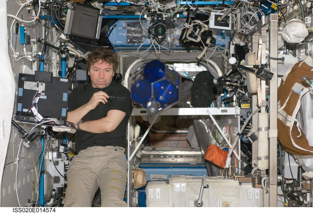 NASA. Public domain (NASA / US government work).
Overview
Section titled “Overview”A free flyer inside a crewed spacecraft has to translate and rotate in six degrees of freedom with nothing to push against, know its position in a cabin where satellite navigation is unavailable, and do both beside crew and equipment that tolerate only small forces and little noise. Ground analogs reproduce part of that. A flat floor with air-bearing platforms gives planar motion [30], the JPL Formation Control Testbed adds a spherical air bearing for three rotational degrees of freedom on a 40 ft floor [29], the Ames Personal Satellite Assistant crane gave five degrees of freedom [20], and parabolic aircraft give seconds of weightlessness at a time [10]. The station itself is not a clean free-fall environment: the quasi-steady regime lies below 0.01 Hz and the vibratory regime from 0.01 to 300 Hz, and a single ATV docking produced a 12.9 mg disturbance at the accelerometer [24]. Earlier shuttle-era measurements put crew exercise at roughly 1 to 4 Hz and pump transients near 1 mg [25]. These figures come from general station and shuttle characterization, not from SPHERES sessions.
SPHERES is a set of self-contained free-flying satellites operated inside the International Space Station as a reprogrammable testbed for guidance, navigation, control and autonomy algorithms for distributed spacecraft. Development began in a senior undergraduate class at the MIT Space Systems Laboratory in autumn 1999 [1]. Two prototypes flew parabolic campaigns on the KC-135 in February and March 2000 and November 2001, and five flight satellites were built at Payload Systems in spring 2002. The program was funded by DARPA and flown through the US Department of Defense Space Test Program [8]. It is formally the SPHERES Laboratory for Distributed Satellite Systems, and its stated purpose is a representative, risk-tolerant environment aboard the station in which metrology, control and autonomy algorithms for distributed satellite systems can be matured through repeated research cycles of increasing complexity [12]. Research supported through the Guest Scientist Program since spring 2000 covers formation flight, communications requirements, mass properties identification, autonomous rendezvous and docking, and tethered formation flight [13].
Three satellites were deployed to the station in 2006 and the facility has been operated by NASA since 2010 [5]; Astrobee was later designed to replace it [4].
Design space and lineage
Section titled “Design space and lineage”Four families of free flyer preceded or followed SPHERES, and they differ most in propulsion and in whether they ever flew.
AERCam Sprint, a 14 in, 35 lb sphere with 12 nitrogen thrusters, flew outside the shuttle on STS-87 in 1997 [21]. As of 2003 no free-flying vehicle had been deployed for operations inside a spacecraft in flight [20]. Mini AERCam was the intended successor: 7.5 in, 10 lb, 12 cold-gas thrusters in four pods, a PowerPC 740 at 266 MHz and a MEMS gyro package sampled at 300 Hz [21]. It was tested on an air-bearing table with nitrogen in place of the flight-design xenon, and ISS-relative GPS was proposed rather than flown [21]. Its autonomy software, a CLIPS expert-system sequencer with a dynamics manager for contingency maneuvers, was exercised on the ground and in hardware-in-the-loop simulation [22].
The Personal Satellite Assistant was the intravehicular line. Model 2 was a 12 in sphere with six pairs of ducted fans, Model 3 was planned with two blowers and four reaction wheels, and the autonomy framework inherited the EUROPA planner from Deep Space One [20]. The paper reports no localization accuracy, endurance or bandwidth figure [20], and its linear thrust capacity is given as 0.5 N [19].
SPHERES took the opposite propulsion choice. Cold gas gives up to 0.2 N per thruster and a 12-thruster layout with any force and torque combination, at the price of a CO2 tank that lasts about 10 minutes and crew who swap it [19]. Fans are quiet and rechargeable but weak: the first Int-Ball produced about 1 mN per fan, which was insufficient to hold pose in some regions of the station [19]. The Astrobee propulsion trade fixed a requirement of 0.6 N maximum thrust on at least one axis and 65 dBA at maximum thrust, and settled on two impellers with flapper nozzles [17]. The flown systems converged on two outcomes: gas for authority in an experiment-driven facility, fans for an assistant that must not disturb the crew.
Navigation diverged in the same way. SPHERES uses fixed ultrasonic and infrared beacons, which confine it to a 2 x 2 x 2 m volume [4]. Int-Ball2 and Astrobee use cameras. Int-Ball2 is 200 mm across and 3.3 kg, with propellers of 51 mN maximum thrust, 1.5 h of operation, visual SLAM and a magnetic docking station, and made its first on-orbit demonstration on 17 October 2023 [27]. Its flight software is ROS based, user programs run in Docker containers on a Jetson TX2, and the visual SLAM cannot run while a user program takes direct access to the navigation camera video [31]. Reinforcement-learning docking for Int-Ball2 has been studied only in simulation: a PPO policy commanding eight propeller thrusts, with success defined as under 2 cm and 2 degrees held for five timesteps [28].
Specifications
Section titled “Specifications”| Parameter | Value | Source |
|---|---|---|
| Wet mass | 4.38 kg | |
| Dry mass | 4.21 kg | |
| Maximum span | 20 x 20 x 25 cm | |
| Structure | 18-sided polyhedron | [8] |
| Wet inertia about the center of mass | 2.30, 2.42, 2.14 x 10^-2 kg m^2 | |
| Center of mass offset from geometric center, wet | (0.48, -1.19, 1.08) mm | |
| Thrusters | 12, cold gas CO2 | [1], [7] |
| Average power | 15 W | |
| Endurance per battery set | about 90 min | [2] |
| Metrology | 24 ultrasonic receivers, 12 IR receivers, 24 IR transmitters | [1], [7] |
Rows with no marker are from [1].
Published mass figures differ. The flight fact sheet dated 21 November 2002 gives 4.38 kg wet and 4.21 kg dry against a 20 x 20 x 25 cm envelope [1]; the NASA facility fact sheet gives 3.5 kg and 0.2 m diameter [8]; the VERTIGO thesis quotes 4.16 kg and 21.3 cm [6]. The fact sheet values are the CAD mass properties for the flight unit including propellant.
Mission profile
Section titled “Mission profile”| Parameter | Value | Source |
|---|---|---|
| Host | International Space Station | [12] |
| Test equipment launched | one beacon and one beacon tester, August 2003 | [1] |
| First satellite delivered | Progress 21P, 24 April 2006 | [1] |
| Second satellite delivered | STS-121, 4 July 2006 | [1] |
| Third satellite delivered | STS-116, 9 December 2006 | [1] |
| Units on orbit | 3, with 3 more retained at MIT for ground work | [7] |
| Facility operated by NASA | from 2010 | [5] |
| Test sessions | more than 50 by September 2013 | [5] |
| Superseded by | Astrobee | [4] |
Mobility
Section titled “Mobility”Translation and rotation are produced by 12 on/off solenoid thrusters fed with carbon dioxide [10]. The thrusters sit at +/-5.16 cm and +/-9.65 cm from the geometric center along the body axes, arranged so that any combination of body forces and torques in six degrees of freedom can be produced [1]. Thrust per thruster is below 0.2 N with a unit-to-unit variability of 0.01 N, and the per-thruster values measured on a single satellite fall between 0.1241 and 0.1340 N. The nozzle exit diameter is 0.838 to 0.844 mm.
The gas path runs from a custom chromoly steel cylinder of 337.5 g dry mass, through a brass pin valve carrying a burst disc that ruptures at 20.7 MPa (3000 psi), to a modified Leland regulator [2]. Tank capacity is 172.4 g of CO2 at 5.93 MPa (860 psig), the vapor pressure of liquid CO2 at 22 C. The regulator cannot be set above 379 kPa (55 psi), and the flight nominal operating pressure is 241 kPa (35 psi) [1]. Downstream of the regulator sit a 25 cm^3 stainless gas capacitor, two relief valves holding the low side below 400 kPa (58 psi), MINSTAC manifold tubing and titanium nozzles rounded to meet crew touch-safety requirements [2]. Solenoid minimum open time is 5 ms as built and is modifiable in the firing circuit, and each solenoid has a latency of about 6 ms, which is one to two orders of magnitude shorter than a typical commanded firing [10].
At the 379 kPa (55 psi) regulator setting the isentropic model gives 6.70 x 10^-4 kg/s per thruster, 0.248 N of thrust and a specific impulse of 37.7 s; at 207 kPa (30 psi) the specific impulse falls to 33.5 s [2]. The prototype propulsion budget assumed about 10 minutes of operation with two to four thrusters at 50 percent duty cycle, and noted that all 12 thrusters firing continuously empty the tank in under one minute [3].
Tests are terminated when a satellite reaches the boundary of the test volume defined by the wall beacons [1].
Power and energy
Section titled “Power and energy”Each satellite carries two packs of AA alkaline cells with a Schottky diode per pack to prevent charging [1]. Average power is 15 W, standby 13.75 W and maximum 16.25 W. Sixteen Duracell Ultra alkaline AA cells are fitted per flight satellite as two eight-packs in parallel at 12 V, giving roughly 90 minutes of operation and drawing about 13.8 W [2]. The bus is stepped to 3.3, 5.0, 12.0 and 22.0 V behind a 1.5 A Polyswitch, with a bypass capacitor sized for the transients thrown by thruster switching. The regulators are Traco TS13.3S2ROSH and TS15.0S2ROSH for the 3.3 V and 5 V rails and MAXIM MAX772, MAX776 and MAX668 for +15 V, -15 V and the 22 V propulsion supply [1].
The prototype used a different arrangement: 13 AA alkaline cells in series at 19.5 V and 2.8 Ah, tested to about 90 minutes with a 6.6 W average draw [3]. Batteries and CO2 tanks are consumables: the crew swaps both on every satellite before each test session, unpacks and stows the supply, and repacks the empty tanks for return to the ground and refilling [4]. The consumable swap is the entire energy resupply path: the satellites carry no solar array and no recharge interface, and were operated for a decade on that basis.
Thermal
Section titled “Thermal”No thermal control design is published. The satellites operate inside the pressurized cabin at crew-compatible temperatures and carry no radiator, heater or coolant loop in any of the retrieved documentation.
Compute and avionics
Section titled “Compute and avionics”Computation runs on a Sundance SMT375 module carrying a Texas Instruments TMS320C6701 digital signal processor at 167 MHz, rated at 1 GFLOPS peak, with 16 MB RAM, 512 kB cache, 224 kB of available ROM and six comports at 20 Mbps [1]. A Xilinx Spartan II XC2S200 FPGA clocked at 25 MHz handles the metrology timing, and a MAX1294 provides six channels of 12-bit analogue-to-digital conversion. The prototype flew a TMS320C40 at 50 MHz with 512 kB of RAM for control and a separate Onset Tattletale 8 built around a Motorola 68332 at 16 MHz for metrology [3].
The inertial measurement unit is three Honeywell accelerometers and three Systron rate gyroscopes, both sampled at up to 1000 Hz [1]. The accelerometers have a sensor range of +/-30 g conditioned to a designed range of +/-25.6 mg across 0 to 4096 counts, giving 12.5 mg/count, with bias under 8 mg, 300 Hz bandwidth, noise under 7 mg rms from 0 to 10 Hz and under 70 mg rms from 10 to 500 Hz, and axis misalignment under 7 mrad. The gyroscopes cover +/-83 deg/s at 30 mV/(deg/s), which is 0.0407 deg/s per count, with bandwidth 50 Hz at the -90 degree point, bias variation over temperature under 3.0 deg/s, short-term bias stability under 0.05 deg/s over 100 s, one-year bias stability under 1.0 deg/s, and noise under 0.05 deg/s/sqrt(Hz) over 0 to 100 Hz [1].
Flight software runs two timer interrupts over a background process [13]. The medium-priority control interrupt executes at any integer frequency up to 25 Hz and can be changed by the control algorithm at any time; the high-priority propulsion interrupt runs at 1 kHz and gives 1 ms pulse-width resolution on the thrusters. A PADS interrupt fires when new sensor data arrive and propagates the state; the low-priority background loop handles communications, position and attitude updates and housekeeping. State is exposed to the algorithm writer through eight global structures covering communications, control, debug, guest scientist code, position and attitude determination, propulsion and housekeeping, system identification and telemetry. Guest algorithms attach through one of three interface frameworks, standard, direct and custom, distributed with source examples and a simulation environment.
Autonomy
Section titled “Autonomy”Navigation uses an ultrasonic time-of-flight system that the program describes as pseudo-GPS [6]. A satellite emits an infrared pulse in all directions; each beacon that receives it replies with a 40 kHz ultrasonic ping after a delay fixed by its address, so the time between the infrared flash and each arrival gives range, and the pattern of which receivers heard the ping gives bearing [7]. The ultrasonic carrier is 40 kHz and five battery-powered beacons are set up in the test area [2]. Beacons ping 20 ms apart in address order, and running only the odd addresses on the five wall beacons widens the spacing to 30 ms [1]. Up to nine beacon addresses can be in use at once.
Each satellite carries 24 ultrasonic receivers, four on each of six faces [7], 12 infrared receivers and 24 infrared transmitters at 880 nm, plus a single onboard ultrasonic beacon 10.7 cm from the geometric center on the docking face [1]. The onboard beacon is what makes relative metrology possible: global metrology fixes the satellite in the ISS frame from the five wall beacons, and relative metrology fixes another satellite in the body frame from its onboard beacon, which emulates a sensor with a limited field of view [7]. Maximum metrology update rate is 6.7 Hz by calculation, nominal rate is 1 to 2 Hz and maximum range is 4 m [1].
The global extended Kalman filter updates at 5 Hz synchronized to the beacon ping cycle, while gyroscope data taken at 1 kHz are batch filtered and downsampled to 20 Hz for attitude propagation [1]. Measured position precision is about +/-1 mm near the center of the test volume where all five beacons are in line of sight, and calibrated ultrasonic range measurements are accurate to within 6 mm. Ranging error after bias correction was characterized at +/-3 mm on the ground, with the global ranging update defaulting to 1 Hz and selectable from 0 to 5 Hz [2].
Thruster commands are produced by a mixing matrix that maps the six-axis force and torque demand onto 12 on-times [10]. The top half of the 6 by 12 matrix holds the calibrated force vector of each thruster and the bottom half the cross product of force and thruster location, and its pseudo-inverse converts a command vector into fractions of the control period for pulse-width modulation. Because propellant burn moves the center of mass and changes the inertia, an online mass property identification routine estimates both from thruster commands and gyroscope data during operation. The reconfigurable control allocation extends the same idea to satellites carrying attached payloads, recomputing the mixing matrix when the configuration changes [11].
Communications
Section titled “Communications”Two independent radio channels operate in the 900 MHz band [8]. Both are half duplex and are carried on a token-ring packet network [2]. Satellite-to-satellite traffic uses an RFM DR-2000 at 916.5 MHz and satellite-to-laptop traffic an RFM DR-2001 at 868.35 MHz, each at 18 kbps and 70 packets per second [1]. The scheme is TDMA with a nominal 150 ms frame that the user can change, carrying 32-byte data packets. The expansion port adds a 32-bit global data bus shared with internal components, 31 address lines, three addressable components and one wired RS232 line at 115 kbps [1].
Payload and instruments
Section titled “Payload and instruments”The expansion port is the reason the facility outlived its original formation-flight charter. Payloads flown on it include VERTIGO for vision-based navigation, RINGS for electromagnetic formation flight, the Slosh experiment for fluid dynamics in microgravity, the Ames smartphone payload, and the InSPIRE-II payloads, which are the Universal Docking Port and the Halo [15]. RINGS was sponsored by DARPA to test electromagnetic formation flight and wireless power transfer: in the formation flight mode a pair of units generate a synchronized alternating magnetic field whose amplitude and phase are independently controlled on each unit, producing attraction, repulsion and torque as a function of separation and relative orientation. The SmartSPHERES payload adds a Samsung Nexus S handset as an embedded controller, contributing a 1 GHz ARM processor, 512 MB of RAM, 16 GB of non-volatile storage, color cameras, temperature, sound, gyroscope and accelerometer sensors, a touchscreen display and Wi-Fi networking, all running Android [5].
VERTIGO adds a stereo camera head and a separate computer. The specification is a 1.2 GHz Via Nano U3300 single-core processor on a Via Pico-ITX P830 board with a VIA VX900 chipset, 4 GB of DDR3-1066, two 64 GB SATA flash disks and Ubuntu Linux 10.04 Server [6]. The cameras are two IDS-Imaging uEye LE 1225-M-HQ units with 1/3 inch monochrome global-shutter CMOS sensors at 640 x 480 and 6 um pixels on a 9.0 cm baseline with hardware exposure timing and synchronization, behind Fujinon 2.8 mm f/1.3 lenses, running at 87 fps maximum and 10 fps typically with exposures from 80 us to 5.5 s. Two Phillips Rebel Star LEDs at 617 nm and 134 lm at 700 mA each provide illumination. Mass is 1.326 kg without battery and power draw is 16 W idle, 20 W typical and 32 W maximum [6]. It launched on Soyuz TMA-06M on 23 October 2012 and completed five test sessions between February 2013 and July 2014 [6], [15].
Docking ports are classified in the SPHERES design work by whether they are androgynous, radially symmetric, rigid, reconfigurable, reusable or single use, and by optional features including electromagnetic attraction and repulsion to brake the closing motion [16]. The Universal Docking Port replaces the Velcro interface with a mechanism. A protruding lance enters a mating hole and a motor secures it, and each port carries a camera and visual markers that measure relative range and angle during the approach [15]. The flight unit is 14 x 10.7 cm and 0.533 kg, operating at a maximum of 6 V and 5 W peak, against a ground prototype of 7.6 x 3.8 cm, 0.45 kg, 24 V and 60 W peak [16]. Both hold a maximum docking tolerance of 1 cm and 2 degrees, but sensing accuracy improved from 1 cm and 0.5 deg on the prototype to better than 2 mm and 1 deg in flight. The prototype carried an electromagnet wound about an iron mechanism to brake the closing motion, which was removed because the flight port is limited to 11.1 V and could not generate useful force at that voltage, and because the added mass reduces the control authority of the satellite [16]. As a payload the port has mass properties of 0.376 kg with a center of mass 2.48 cm from the primary interface, which the reconfigurable control allocation has to account for [14].
Modes of operation
Section titled “Modes of operation”The baseline docking interface is four 1 inch square Velcro patches, two of hooks and two of loops, arranged around the ultrasonic beacon on the docking face in a pattern identical on every satellite, so any pair can mate [1]. It tolerates +/-1.5 cm of position error and +/-5 degrees of attitude error at contact. On orbit the Velcro was found not to latch reliably when two satellites make an aligned contact at low approach velocity, and undocking requires the crew to pull the satellites apart.
Autonomous docking to a fixed beacon from about 1.2 m separation used a commanded 2.07 cm/s acceleration pulse that achieved 1.85 cm/s and a commanded 0.65 cm/s braking pulse that achieved 0.63 cm/s, holding attitude error under 6 degrees through the glideslope phase and tangential alignment inside a 2 cm by 2 cm box [1]. Docking to a target tumbling at 2.25 deg/s about its z body axis from about 0.6 m held approach velocity within 5 mm/s of the commanded value for 70 percent of the run, with contact at 111 s in the first attempt and 116 s in the second.
Docking missions are decomposed into rendezvous, proximity operations, docking, manipulation of the target and undocking, and the docking port payloads exist so that control algorithms for each part can be exercised on orbit [15]. Formation initialization was run as a distinct mode. Satellites are deployed with no knowledge of each other’s positions, acquire each other with the limited-field-of-view relative sensor, null the range rates and then take station in the array [7]. Fuel balancing regulates consumption across the formation so that mission duration is set by the fleet rather than by the first satellite to run dry.
Ground operations
Section titled “Ground operations”Test sessions run in the US Laboratory near the hatch, with the five beacons mounted on the walls to define the test volume [1]. SPHERES is not operated in the Russian segment [8]. A session is about 3.5 hours and contains roughly 8 to 12 tests of 10 to 15 minutes each, with sessions about a month apart.
The cycle is fixed. The MIT team is notified about two weeks before a session; the software, already written, is integrated and verified on the MIT 2-D air table; it goes to the DoD Space Test Program office one week ahead for upload [1]. During the session the team watches video and audio in real time over a high-bandwidth link to NASA and passes instructions to the crew member on request. Telemetry is stored on the ISS laptop and emailed to MIT about three days later; the video recording follows a few weeks after that. VERTIGO produces more than 10 GB per session, which is downlinked with weeks of latency because no science result depends on getting it quickly [6].
Ground development before flight used the KC-135 for parabolic tests in August 2002, February 2003 and November 2003, and the MSFC flat floor for autonomous docking to a rotating target in June 2004, tethered formation flight in December 2004, and SWARM assembly and reconfiguration in July and September 2006 [1]. The Guest Scientist Program was developed in autumn 2002, the Universal Docking Port in spring 2005 and the Miniature Video Docking Sensor in summer 2005.
Utilization totals were 36 sessions in the first six years to 2012 [6] and more than 50 test sessions by September 2013 [5].
Technologies developed
Section titled “Technologies developed”The program produced a design method as well as hardware. Seven principles for a microgravity technology maturation laboratory were formulated from the SPHERES experience: iterative research, enabling a field of study, optimized utilization, focused modularity, remote operations and usability, incremental technology maturation, and requirements balance [12]. Requirements balance is the oversight principle over the other six. The principles were derived by identifying the features that let SPHERES satisfy the MIT laboratory design philosophy and then testing their applicability to technology maturation generally, and the same framework was then turned back on SPHERES to propose a further design iteration. The Guest Scientist Program is the operational expression of iterative research, giving outside investigators source access, a simulator and three levels of software interface so that an algorithm can be revised between monthly sessions [12], [13].
Online mass property identification, developed because trifilar torsional pendulum measurements of the principal moments of inertia differed from the CAD predictions by 5.4 to 10.5 percent and because propellant burn moves the center of mass, is the technique that made repeatable control possible across a session [10]. Reconfigurable control allocation extended it to satellites with attached payloads [11], [14]. Vision-based relative navigation matured on VERTIGO: the goggles pose solution differed from the ultrasonic solution by a mean of 1.59 cm in X with a standard deviation of 0.920 cm, velocity differences were typically under 1 mm/s, and geometric reconstruction of the target hull had a mean absolute error of 0.183 cm against hand measurement [6].
Successors and flight record
Section titled “Successors and flight record”Astrobee was designed to replace the SPHERES facility, addressing the limits the SPHERES architecture had reached: beacon triangulation confines a satellite to the two-meter cube defined by the fixed beacons, the CO2 and battery consumables cost crew time, and safety rules forbid operation without crew supervision [4]. The joint review by the three free-flyer teams reaches the same point from the operations side: platforms with a docking station fly often, and SPHERES, the first Int-Ball and CIMON needed crew setup every session [18]. Astrobee is a 32 cm cube of about 10 kg driven by fans rather than cold gas, so its only consumable is battery charge, which it replenishes by docking itself [4]. Its flight software is split across three ARM processors, one Android and two Linux: a low level processor closing the propulsion loop against the inertial measurement unit at about 100 Hz and safing the system if the others fault, a mid level processor hosting most of the flight software, and a high level processor that drives the crew touchscreen and runs guest science software in isolation from the flight software [9]. The 2015 prototype avionics and a first perching arm were benchmarked on the ground; the arm weighed 315 g against a 200 g requirement [23]. Large files transfer over a hard-wired Ethernet connection at the dock [4].
Flight results exist for Astrobee and not for the planning documents above. Through May 2025 the facility completed more than 165 real-time operations and more than 90 Guest Science sessions, with more than 1200 hours of console support, about 220 of which involved crew; the unit named Bumble flew 135 sessions, the dock 164, and the perching arms 23 [17]. The AstroLoc localizer reached 0.0491 m position RMSE in localization mode and 0.2777 m in visual-inertial-only mode over 12 ISS activities, against a ground truth produced by the authors’ own offline mapping [17]. Maximum design speed is about 2.1 m/s, with an over-speed cutoff at 50 cm/s chosen to keep bumper impact below the 556 N astronaut push-off certification. On 27 May 2025 a reinforcement-learning controller was flown on Bumble in one session of about 7 minutes and 8 maneuvers; it did not match the baseline controller’s final position and orientation error in any test, and the first of two docking attempts failed [26]. Mini AERCam, the Personal Satellite Assistant and the learned Int-Ball2 docking policy remain at ground test, design or simulation level.
Localization, survey and learned control on Astrobee
Section titled “Localization, survey and learned control on Astrobee”The Astrobee localizer is the part of the successor lineage with the longest published record. The original estimator fused a 62.5 Hz inertial unit with sparse-map landmarks, docking tags and handrail detections at roughly 2 to 5 Hz, and on the ground reached position RMSE from about 5 cm on a slow circle to 16.5 cm on a fast combined motion [32]. It was tested on the ground only, against an overhead-camera reference [32]. AstroLoc replaced it on the ISS units with a factor-graph estimator, cutting average runtime from 1.13 s to 0.21 s and removing the two lost-localization events the previous localizer had on the public ISS dataset [33]. AstroLoc2 separated odometry from map-based correction and lowered absolute trajectory error RMSE by 16 percent over AstroLoc on 10 ISS activities; it is less accurate than DSO and ORB-SLAM3 and runs 41 and 87 percent faster than them [37]. In both cases the reference trajectory is itself imperfect [33], [37].
Two further flown results use the same platform as an instrument. Adding learned object semantics to the sparse-map localizer lowered position RMSE on all five ISS datasets tested, but the detector covered 8 object classes trained on one trajectory, ran offline, and was scored against the pipeline that built the maps [34]. A two-robot change detection scheme recovered unmodified objects in JEM surveys from batches of about seven navigation images, with no detection rate or position error reported [35]. Survey flights in 2022 with the ISAAC payload measured Wi-Fi signal strength through the US Laboratory, Node 2 and the JEM, and found a fitted pathloss exponent of 0.084 along the module axis, so the free-space inverse-square model does not hold; the radio was not characterized before flight, so only relative differences are reliable [36].
Learned control has one flight: a PPO policy trained with curriculum learning in simulation, checked on the Ames air-bearing table (2 degrees of freedom) and flown on Astrobee, replacing the wrench controller [38]. Only the curriculum-trained policy was flown, and the success statistics come from the training simulator [38]. Free-flyer inspection autonomy for a lunar-orbit outpost with keep-in corridors and keep-out zones has been exercised only in MuJoCo simulation, where four simultaneous thruster failures drive the vehicle into the station [39]. It has no hardware result.
Across the lineage, the SPHERES-era contribution that carried forward was the way of working rather than the vehicle: the guest-investigator interface, ground verification on an air table before upload, and a plant model identified from the vehicle itself. The vehicles that followed dropped its propulsion and its beacon metrology and kept that cycle.
What is not established
Section titled “What is not established”The plant parameters of the flight satellites are bench and parabolic-flight values, not station values. Thruster strengths, center of mass offsets and inertias come from MIT bench tests and reduced-gravity aircraft sessions in February 2002 with 15 to 40 tests per satellite; load cell mount play of 0.5 mm and liquid CO2 motion remain unresolved error sources in the center of mass, and absolute thruster latency was never measured [10]. Published masses disagree (4.38, 4.16 and 3.5 kg), and no thermal design is available. The SPHERES papers cited do not characterize the acceleration environment at the test volume, so the disturbance figures above are station-wide and shuttle-era values [24], [25], and the ATV event is a single docking with no repeat [24].
Comparisons between free flyers rest on secondhand tables. Thrust figures are defined per nozzle, per fan or as an axis resultant depending on the platform, and the Int-Ball2 navigation error is bounded by a reference marker system with its own error of 28 mm and 1.1 degrees [18], [27]. The Int-Ball and CIMON figures in the Astrobee operations paper are quoted from JAXA and DLR sources and the Astrobee values there are design values [4]. A simulation of an Astrobee-class flyer grasping cargo bags of 1 to 15.4 kg found that the base stabilization torque exceeds the assumed 0.02 N m limit for the heavier bags, using actuator limits taken from a public model and no hardware validation [19]. The Astrobee localization error floor is not independent of the mapping pipeline that defines the ground truth [17], and the reinforcement-learning flight is a single session [26]. Mini AERCam and PSA sources report no flight and, for PSA, no performance measurements [21], [20].
References
Section titled “References”References
- Nolet, S. (2007). Development of a Guidance, Navigation and Control Architecture and Validation Process Enabling Autonomous Docking to a Tumbling Satellite. Source
BibTeX
@phdthesis{nolet2007development, title = {Development of a Guidance, Navigation and Control Architecture and Validation Process Enabling Autonomous Docking to a Tumbling Satellite}, author = {Nolet, Simon}, school = {Massachusetts Institute of Technology}, type = {Ph.D. thesis}, year = {2007}, url = {https://dspace.mit.edu/handle/1721.1/38598} } - Chen, A. (2002). Propulsion System Characterization for the SPHERES Formation Flight and Docking Testbed. Source
BibTeX
@mastersthesis{chen2002propulsion, title = {Propulsion System Characterization for the SPHERES Formation Flight and Docking Testbed}, author = {Chen, Allen}, school = {Massachusetts Institute of Technology}, type = {S.M. thesis}, year = {2002}, url = {https://dspace.mit.edu/handle/1721.1/16736} } - Saenz-Otero, A. (2000). The SPHERES Satellite Formation Flight Testbed: Design and Initial Control. Source
BibTeX
@mastersthesis{saenzotero2000spheres, title = {The SPHERES Satellite Formation Flight Testbed: Design and Initial Control}, author = {Saenz-Otero, Alvar}, school = {Massachusetts Institute of Technology}, type = {M.Eng. thesis}, year = {2000}, url = {https://dspace.mit.edu/handle/1721.1/86730} } - Bualat, M. G., Smith, T., Fong, T. W., Smith, E. E. and Wheeler, D. W. (2018). Astrobee: A New Tool for ISS Operations
. SpaceOps Conference. Source
BibTeX
@inproceedings{bualat2018astrobee, title = {Astrobee: A New Tool for ISS Operations}, author = {Bualat, Maria G. and Smith, Trey and Fong, Terrence W. and Smith, Ernest E. and Wheeler, D. W.}, booktitle = {SpaceOps Conference}, address = {Marseille, France}, year = {2018}, doi = {10.2514/6.2018-2517}, abstract = {The Astrobee} } - Fong, T., Micire, M., Morse, T., Park, E., Provencher, C., To, V., Wheeler, D. W., Mittman, D., Torres, R. J. and Smith, E. (2013). Smart SPHERES: a Telerobotic Free-Flyer for Intravehicular Activities in Space
. AIAA SPACE Conference. Source
BibTeX
@inproceedings{fong2013smart, title = {Smart SPHERES: a Telerobotic Free-Flyer for Intravehicular Activities in Space}, author = {Fong, Terrence and Micire, Mark and Morse, Ted and Park, Eric and Provencher, Chris and To, Vinh and Wheeler, D. W. and Mittman, David and Torres, R. Jay and Smith, Ernest}, booktitle = {AIAA SPACE Conference}, publisher = {American Institute of Aeronautics and Astronautics}, address = {San Diego, California}, year = {2013}, doi = {10.2514/6.2013-5338}, abstract = {Smart SPHERES is a prototype free-flying space robot based on the SPHERES platform. Smart SPHERES can be remotely operated by astronauts inside a spacecraft, or by mission controllers on the ground. We developed Smart SPHERES to perform a variety of intravehicular activities (IVA), such as operations inside the International Space Station (ISS). These IVA tasks include environmental monitoring surveys (radiation, sound levels, etc.), inventory, and mobile camera work. In this paper, we first discuss the motivation for free-flying space robots. We then describe the development of the Smart SPHERES prototype, including avionics, software, and data communications. Finally, we present results of initial flight tests on-board the ISS.} } - Tweddle, B. E. (2013). Computer Vision-Based Localization and Mapping of an Unknown, Uncooperative and Spinning Target for Spacecraft Proximity Operations. Source
BibTeX
@phdthesis{tweddle2013computer, title = {Computer Vision-Based Localization and Mapping of an Unknown, Uncooperative and Spinning Target for Spacecraft Proximity Operations}, author = {Tweddle, Brent E.}, school = {Massachusetts Institute of Technology}, type = {Ph.D. thesis}, year = {2013}, url = {https://dspace.mit.edu/handle/1721.1/85693} } - Mandy, C. P., Sakamoto, H., Saenz-Otero, A. and Miller, D. W. (2007). Implementation of Satellite Formation Flight Algorithms Using SPHERES Aboard the International Space Station
. AIAA Guidance, Navigation, and Control Conference, 20080012634. Source
BibTeX
@inproceedings{mandy2007implementation, title = {Implementation of Satellite Formation Flight Algorithms Using SPHERES Aboard the International Space Station}, author = {Mandy, Christophe P. and Sakamoto, Hiraku and Saenz-Otero, Alvar and Miller, David W.}, booktitle = {AIAA Guidance, Navigation, and Control Conference}, number = {20080012634}, institution = {NASA}, year = {2007}, url = {https://ntrs.nasa.gov/citations/20080012634}, abstract = {The MIT's Space Systems Laboratory developed the Synchronized Position Hold Engage and Reorient Experimental Satellites (SPHERES) as a risk-tolerant spaceborne facility to develop and mature control, estimation, and autonomy algorithms for distributed satellite systems for applications such as satellite formation flight. Tests performed study interferometric mission-type formation flight maneuvers in deep space. These tests consist of having the satellites trace a coordinated trajectory under tight control that would allow simulated apertures to constructively interfere observed light and measure the resulting increase in angular resolution. This paper focuses on formation initialization (establishment of a formation using limited field of view relative sensors), formation coordination (synchronization of the different satellite s motion) and fuel-balancing among the different satellites.} } - Miller, D. W., Wilson, E., How, J., Saenz-Otero, A. and Chamitoff, G. (2009). Synchronized Position Hold, Engage, Reorient, Experimental Satellites
. NASA, 20090014826. Source
BibTeX
@techreport{miller2009synchronized, title = {Synchronized Position Hold, Engage, Reorient, Experimental Satellites}, author = {Miller, David W. and Wilson, Edward and How, Jonathan and Saenz-Otero, Alvar and Chamitoff, Gregory}, number = {20090014826}, institution = {NASA}, year = {2009}, url = {https://ntrs.nasa.gov/citations/20090014826}, abstract = {Synchronized Position Hold, Engage, Reorient, Experimental Satellites (SPHERES) are bowling-ball sized spherical satellites. They will be used inside the space station to test a set of well-defined instructions for spacecraft performing autonomous rendezvous and docking maneuvers. Three free-flying spheres will fly within the cabin of the station, performing flight formations. Each satellite is self-contained with power, propulsion, computers and navigation equipment. The results are important for satellite servicing, vehicle assembly and formation flying spacecraft configurations. SPHERES is a testbed for formation flying by satellites, the theories and calculations that coordinate the motion of multiple bodies maneuvering in microgravity. To achieve this inside the ISS cabin, bowling-ball-sized spheres perform various maneuvers (or protocols), with one to three spheres operating simultaneously . The Synchronized Position Hold, Engage, Reorient, Experimental Satellites (SPHERES) experiment will test relative attitude control and station-keeping between satellites, re-targeting and image plane filling maneuvers, collision avoidance and fuel balancing algorithms, and an array of geometry estimators used in various missions. SPHERES consists of three self-contained satellites, which are 18 sided polyhedrons that are 0.2 meter in diameter and weigh 3.5 kilograms. Each satellite contains an internal propulsion system, power, avionics, software, communications, and metrology subsystems. The propulsion system uses CO2, which is expelled through the thrusters. SPHERES satellites are powered by AA batteries. The metrology subsystem provides real-time position and attitude information. To simulate ground station-keeping, a laptop will be used to transmit navigational data and formation flying algorithms. Once these data are uploaded, the satellites will perform autonomously and hold the formation until a new command is given.} } - Bualat, M., Barlow, J., Fong, T., Provencher, C., Smith, T. and Zuniga, A. (2015). Astrobee: Developing a Free Flying Robot for the International Space Station
. AIAA SPACE Conference, 20150018250. Source
BibTeX
@inproceedings{bualat2015astrobee, title = {Astrobee: Developing a Free Flying Robot for the International Space Station}, author = {Bualat, Maria and Barlow, Jonathan and Fong, Terrence and Provencher, Christopher and Smith, Trey and Zuniga, Allison}, booktitle = {AIAA SPACE Conference}, number = {20150018250}, institution = {NASA}, year = {2015}, doi = {10.2514/6.2015-4643}, abstract = {Astronaut time will always be in short supply, consumables (e.g., oxygen) will always be limited, and some work will not be feasible, or productive, for astronauts to do manually. Free flyers offer significant potential to perform a great variety of tasks, include routine, repetitive or simple but long-duration work, such as conducting environment surveys, taking sensor readings or monitoring crew activities. The "Astrobee" project is developing a new free flying robot system suitable for performing Intravehicular Activity (IVA) work on the International Space Station (ISS). This paper will describe the Astrobee project objectives, initial design, concept of operations, and key challenges.\n\n\n} } - Berkovitz, D. S. (2008). System Characterization and Online Mass Property Identification of the SPHERES Formation Flight Testbed. Source
BibTeX
@mastersthesis{berkovitz2008system, title = {System Characterization and Online Mass Property Identification of the SPHERES Formation Flight Testbed}, author = {Berkovitz, Dustin S.}, school = {Massachusetts Institute of Technology}, type = {S.M. thesis}, year = {2008}, url = {https://dspace.mit.edu/handle/1721.1/45260} } - Mohan, S., Saenz-Otero, A., Nolet, S., Miller, D. W. and Sell, S. (2009). SPHERES Reconfigurable Framework and Control System Design for Autonomous Assembly
. AIAA Guidance, Navigation, and Control Conference. Source
BibTeX
@inproceedings{mohan2009spheres, title = {SPHERES Reconfigurable Framework and Control System Design for Autonomous Assembly}, author = {Mohan, Swati and Saenz-Otero, Alvar and Nolet, Simon and Miller, David W. and Sell, Steven}, booktitle = {AIAA Guidance, Navigation, and Control Conference}, year = {2009}, doi = {10.2514/6.2009-5978}, abstract = {Reconfigurable control system design is a key component for enabling autonomous on-orbit assembly. Current research on reconfigurable control systems focuses on adapting to failures. However, for assembly scenarios, the reconfiguration is necessitated by changing mass and stiffness properties. This paper provides a brief description of existing reconfigurable control system technology and develops a framework to incorporate reconfiguration into an existing baseline system to account for mass property variations. The reconfigurable control system framework has been developed and implemented using the SPHERES (Synchronized Position Hold Engage Reorient Experimental Satellites) testbed as the baseline system. The framework highlights the elements that need to be updated, introduces a variable p that captures the configuration, and details the updates necessary in the key algorithms to calculate the model on-line using p. Results are presented from the implementation on the SPHERES, focusing on the reconfigurable estimator. Plans are presented for an integrated assembly test that demonstrates the maintenance of stability, fuel efficiency, and accuracy throughout configuration changes that occur during assembly.} } - Saenz-Otero, A. (2005). Design Principles for the Development of Space Technology Maturation Laboratories Aboard the International Space Station. Source
BibTeX
@phdthesis{saenzotero2005design, title = {Design Principles for the Development of Space Technology Maturation Laboratories Aboard the International Space Station}, author = {Saenz-Otero, Alvar}, school = {Massachusetts Institute of Technology}, type = {Ph.D. thesis}, year = {2005}, url = {https://dspace.mit.edu/handle/1721.1/33065} } - Hilstad, M. O. (2002). A Multi-Vehicle Testbed and Interface Framework for the Development and Verification of Separated Spacecraft Control Algorithms. Source
BibTeX
@mastersthesis{hilstad2002multi, title = {A Multi-Vehicle Testbed and Interface Framework for the Development and Verification of Separated Spacecraft Control Algorithms}, author = {Hilstad, Mark O.}, school = {Massachusetts Institute of Technology}, type = {S.M. thesis}, year = {2002}, url = {https://dspace.mit.edu/handle/1721.1/16738} } - Mohan, S. (2007). Reconfiguration Methods for On-Orbit Servicing, Assembly, and Operations with Application to Space Telescopes. Source
BibTeX
@mastersthesis{mohan2007reconfiguration, title = {Reconfiguration Methods for On-Orbit Servicing, Assembly, and Operations with Application to Space Telescopes}, author = {Mohan, Swati}, school = {Massachusetts Institute of Technology}, type = {S.M. thesis}, year = {2007}, url = {https://dspace.mit.edu/handle/1721.1/42055} } - Hilton, A. R. (2015). A Performance-Driven Experiment Framework for Space Technology Development Using the International Space Station. Source
BibTeX
@mastersthesis{hilton2015performance, title = {A Performance-Driven Experiment Framework for Space Technology Development Using the International Space Station}, author = {Hilton, Andrew R.}, school = {Massachusetts Institute of Technology}, type = {S.M. thesis}, year = {2015}, url = {https://dspace.mit.edu/handle/1721.1/98559} } - Miller, D. L. (2015). Development of Resource-Constrained Sensors and Actuators for In-Space Satellite Docking and Servicing. Source
BibTeX
@mastersthesis{miller2015development, title = {Development of Resource-Constrained Sensors and Actuators for In-Space Satellite Docking and Servicing}, author = {Miller, Duncan L.}, school = {Massachusetts Institute of Technology}, type = {S.M. thesis}, year = {2015}, url = {https://dspace.mit.edu/handle/1721.1/98805} } - Alexandrov, O., Barlow, J., Benavides, J., Bualat, M., Carlino, R., Coltin, B., Cortez, J., Daley, E., Feller, J., Flückiger, L., Fong, T., Fusco, J., Garcia Ruiz, R., Hamilton, K., Kanis, S., Katterhagen, A., Kim, Y., Love, J. F., McIntyre, M., McLachlan, B., Mora Vargas, A., Moratto, Z., Moreira, M., Morse, T., Orosco, H., Park, I.-W., Provencher, C., Sanchez, H., Sharif, K., Smith, E., Smith, T., Soussan, R., Symington, A., Talavera, R. O., To, V., Wheeler, D. and Yoo, J. (2026). Astrobee: Free-Flying Robots for the International Space Station
. IEEE Transactions on Field Robotics. Source
BibTeX
@article{alexandrov2026astrobee, title = {Astrobee: Free-Flying Robots for the International Space Station}, author = {Alexandrov, Oleg and Barlow, Jonathan and Benavides, Jose and Bualat, Maria and Carlino, Roberto and Coltin, Brian and Cortez, Jose and Daley, Earl and Feller, Jeffrey and Flückiger, Lorenzo and Fong, Terrence and Fusco, Jesse and Garcia Ruiz, Ruben and Hamilton, Kathryn and Kanis, Simeon and Katterhagen, Aric and Kim, Yunkyung and Love, John F. and McIntyre, Michael and McLachlan, Blair and Mora Vargas, Andres and Moratto, Zack and Moreira, Marina and Morse, Theodore and Orosco, Henry and Park, In-Won and Provencher, Christopher and Sanchez, Hugo and Sharif, Khaled and Smith, Ernest and Smith, Trey and Soussan, Ryan and Symington, Andrew and Talavera, Rafael Omar and To, Vinh and Wheeler, DW and Yoo, Jongwoon}, journal = {IEEE Transactions on Field Robotics}, year = {2026}, url = {https://ntrs.nasa.gov/citations/20260001396}, abstract = {The Astrobees are free-flying robots that operate inside the International Space Station (ISS) and were launched to the ISS in 2019. Since then they have successfully performed hundreds of activities in space supporting almost two dozen separate research projects. The robots were designed to overcome multiple challenges unique to the ISS environment, including safety, upgradeability and maintainability, limited mass and computation, and unique localization challenges from lack of gravity and a constantly changing environment. This article provides an overview of Astrobee, from hardware and software design to deployment results and activities.} } - Yamaguchi, S. P., Mora Vargas, A., Eisenberg, T., Rogon, C., Yamamoto, T., Inoue, S., Kössl, C., Coltin, B., Smith, T. and Benavides, J. V. (2025). Free-Flying Crew Cooperative Robots on the ISS: A Joint Review of Astrobee, CIMON, and Int-Ball Operations
. International Conference on Space Robotics. Source
BibTeX
@inproceedings{yamaguchi2026free, title = {Free-Flying Crew Cooperative Robots on the ISS: A Joint Review of Astrobee, CIMON, and Int-Ball Operations}, author = {Yamaguchi, Seiko Piotr and Mora Vargas, Andres and Eisenberg, Till and Rogon, Christian and Yamamoto, Tatsuya and Inoue, Shona and Kössl, Christoph and Coltin, Brian and Smith, Trey and Benavides, Jose V.}, booktitle = {International Conference on Space Robotics}, pages = {402-409}, year = {2025}, doi = {10.1109/isparo66239.2025.11436992}, abstract = {Intra-vehicular free-flying robots are anticipated to support various work in human spaceflight while working side-by-side with astronauts. Such example of robots includes NASA’s Astrobee, DLR’s CIMON, and JAXA’s Int-Ball, which are deployed on the International Space Station. This paper presents the first joint analyses of these robot’s shared experiences, co-authored by their development and operation team members. Despite the different origins and design philosophies, the development and operations of these platforms encountered various convergences. Hence, this paper presents a detailed overview of these robots, presenting their objectives, design, and onboard operations. Hence, joint lessons learned across the lifecycle are presented, from design to on-orbit operations. These lessons learned are anticipated to serve for future development and research as design recommendations.} } - Turchetti, F., Ekal, M., Lii, N. Y. and Roa, M. A. (2024). Analysis of Intra-Vehicular Robotic Free-Flyers and Their Manipulation Capabilities
. International Astronautical Congress, IAC-24-A2.5.10. Source
BibTeX
@inproceedings{turchetti2024analysis, title = {Analysis of Intra-Vehicular Robotic Free-Flyers and Their Manipulation Capabilities}, author = {Turchetti, Federico and Ekal, Monica and Lii, Neal Y. and Roa, Maximo A.}, booktitle = {International Astronautical Congress}, number = {IAC-24-A2.5.10}, year = {2024}, url = {https://elib.dlr.de/208576/} } - Dorais, G. A. and Gawdiak, Y. (2003). The Personal Satellite Assistant: An Internal Spacecraft Autonomous Mobile Monitor
. IEEE Aerospace Conference. Source
BibTeX
@inproceedings{dorais2003personal, title = {The Personal Satellite Assistant: An Internal Spacecraft Autonomous Mobile Monitor}, author = {Dorais, Gregory A. and Gawdiak, Y.}, booktitle = {IEEE Aerospace Conference}, volume = {1}, pages = {1-348}, year = {2003}, doi = {10.1109/aero.2003.1235064}, abstract = {This paper presents an overview of the research and development effort at the NASA Ames Research Center to create an internal spacecraft autonomous mobile monitor capable of performing intra-vehicular sensing activities by autonomously navigating onboard the International Space Station. We describe the capabilities, mission roles, rationale, high-level functional requirements, and design challenges for an autonomous mobile monitor. The rapid prototyping design methodology used, in which five prototypes of increasing fidelity are designed, is described as well as the status of these prototypes, of which two are operational and being tested, and one is actively being designed. The physical test facilities used to perform ground testing are briefly described, including a micro-gravity test facility that permits a prototype to propel itself in 3 dimensions with 6 degrees-of-freedom as if it were in a micro-gravity environment. We also describe an overview of the autonomy framework and its components including the software simulators used in the development process. Sample mission test scenarios are also described. The paper concludes with a discussion of future and related work followed by the summary.} } - Fredrickson, S. E., Abbott, L. W., Duran, S., Jochim, J. D., Studak, J. W., Wagenknecht, J. D. and Williams, N. M. (2003). Mini AERCam: Development of a Free-Flying Nanosatellite Inspection Robot
. Space. Source
BibTeX
@inproceedings{fredrickson2003mini, title = {Mini {AERCam}: Development of a Free-Flying Nanosatellite Inspection Robot}, author = {Fredrickson, Steven E. and Abbott, Larry W. and Duran, Steve and Jochim, J. David and Studak, J. William and Wagenknecht, Jennifer D. and Williams, Nichole M.}, booktitle = {Space}, volume = {5088}, pages = {97-111}, publisher = {SPIE}, year = {2003}, doi = {10.1117/12.498108}, abstract = {The Engineering Directorate of NASA Johnson Space Center has developed a nanosatellite-class free-flyer intended for future external inspection and remote viewing of human spaceflight activities, including International Space Station (ISS) operations. The Miniature Autonomous Extravehicular Robotic Camera (Mini AERCam) technology demonstration unit has been integrated into the approximate form and function of a flight system. The spherical Mini AERCam free flyer is 7.5 inches in diameter and weighs approximately 10 pounds, yet it incorporates significant additional capabilities compared to the 35 pound, 14 inch AERCam Sprint that flew as a Shuttle flight experiment in 1997. Mini AERCam hosts a full suite of miniaturized avionics, instrumentation, communications, navigation, imaging, power, and propulsion subsystems, including two digital video cameras and a high resolution still image camera. The vehicle is designed for either remotely piloted operations or supervised autonomous operations including automatic stationkeeping and point-to-point maneuvering. Free-flyer testing has been conducted on an air-bearing table and in a six degree-of-freedom closed-loop orbital simulation. The orbital simulation models the three-dimensional dynamics of the free-flyer in proximity to the ISS, and produces corresponding God's eye views and simulated free-flyer camera views. A high-fidelity simulation is achieved by directly interfacing to free-flyer thruster driver signals, emulating the MEMS gyro responses in hardware, and using the "truth" state to drive a GPS signal generator connected to the free-flyer GPS receiver.} } - Fredrickson, S., Duran, S., Braun, A., Straube, T. and Mitchell, J. (2006). AERCam Autonomy: Intelligent Software Architecture for Robotic Free Flying Nanosatellite Inspection Vehicles
. Space. Source
BibTeX
@inproceedings{fredrickson2006aercam, title = {AERCam Autonomy: Intelligent Software Architecture for Robotic Free Flying Nanosatellite Inspection Vehicles}, author = {Fredrickson, Steven and Duran, Steve and Braun, Angela and Straube, Timothy and Mitchell, Jennifer}, booktitle = {Space}, year = {2006}, doi = {10.2514/6.2006-7392}, abstract = {The NASA Johnson Space Center has developed a nanosatellite-class Free Flyer intended for future external inspection and remote viewing of human spacecraft.The Miniature Autonomous Extravehicular Robotic Camera (Mini AERCam) technology demonstration unit has been integrated into the approximate form and function of a flight system.The spherical Mini AERCam Free Flyer is 7.5 inches in diameter and weighs approximately 10 pounds, yet it incorporates significant additional capabilities compared to the 35-pound, 14inch diameter AERCam Sprint that flew as a Shuttle flight experiment in 1997.Mini AERCam hosts a full suite of miniaturized avionics, instrumentation, communications, navigation, power, propulsion, and imaging subsystems, including digital video cameras and a high resolution still image camera.The vehicle is designed for either remotely piloted operations or supervised autonomous operations, including automatic stationkeeping, pointto-point maneuvering, and waypoint tracking.The Mini AERCam Free Flyer is accompanied by a sophisticated control station for command and control, as well as a docking system for automated deployment, docking, and recharge at a parent spacecraft.Free Flyer functional testing has been conducted successfully on both an airbearing table and in a six-degree-of-freedom closed-loop orbital simulation with avionics hardware in the loop.Mini AERCam aims to provide beneficial on-orbit views that cannot be obtained from fixed cameras, cameras on robotic manipulators, or cameras carried by crewmembers during extravehicular activities (EVA's).On Shuttle or International Space Station (ISS), for example, Mini AERCam could support external robotic operations by supplying orthogonal views to the intravehicular activity (IVA) robotic operator, supply views of EVA operations to IVA and/or ground crews monitoring the EVA, and carry out independent visual inspections of areas of interest around the spacecraft.To enable these future benefits with minimal impact on IVA operators and ground controllers, the Mini AERCam system architecture incorporates intelligent systems attributes that support various autonomous capabilities.1) A robust command sequencer enables task-level command scripting.Command scripting is employed for operations such as automatic inspection scans over a region of interest, and operator-hands-off automated docking.2) A system manager built on the same expert-system software as the command sequencer provides detection and smartresponse capability for potential system-level anomalies, like loss of communications between the Free Flyer and control station.3) An AERCam dynamics manager provides nominal and off-nominal management of guidance, navigation, and control (GN&C) functions.It is employed for safe trajectory monitoring, contingency maneuvering, and related roles.This paper will describe these architectural components of Mini AERCam autonomy, as well as the interaction of these elements with a human operator during supervised autonomous control.} } - Yoo, J., Park, I.-W., To, V., Lum, J. Q. H. and Smith, T. (2015). Avionics and perching systems of free-flying robots for the International Space Station
. AIAA Guidance, Navigation, and Control Conference. Source
BibTeX
@inproceedings{yoo2015avionics, title = {Avionics and perching systems of free-flying robots for the International Space Station}, author = {Yoo, Jongwoon and Park, In-Won and To, Vinh and Lum, Jason Q. H. and Smith, Trey}, booktitle = {AIAA Guidance, Navigation, and Control Conference}, publisher = {IEEE}, year = {2015}, doi = {10.1109/syseng.2015.7302756}, abstract = {This paper introduces NASA's new free-flying robot, Astrobee, especially focusing on its avionics and perching subsystems. Astrobee is a cube-shaped autonomous robot designed for various missions on the International Space Station (ISS). Its major goal is to offload routine and repetitive work from the ISS crews and assist their science activities. Astrobee is also designed for scientists to use it as a micro-gravity robotics research platform. It can host various science equipment and software, allowing scientists to conduct their experiments using Astrobees on the ISS. The robot has a small compliant, detachable arm with a griper so that it can perch on the ISS wall to support long duration tasks. This arm will grasp ISS handrails to hold its position without using propulsion or navigation subsystems to minimize power consumption. Due to its special missions and operating environment, Astrobee has a set of unique design requirements. This paper gives an overview of Astrobee and the details of its avionics and perching subsystems with distinctive design challenges. We also present the trade studies that we have conducted to decide the critical hardware and software components for the avionics.} } - McPherson, K., Kelly, E. and Keller, J. (2009). Acceleration Environment of the International Space Station
. AIAA Aerospace Sciences Meeting including The New Horizons Forum and Aerospace Exposition, 20120012936. Source
BibTeX
@inproceedings{mcpherson2009acceleration, title = {Acceleration Environment of the International Space Station}, author = {McPherson, Kevin and Kelly, Eric and Keller, Jennifer}, booktitle = {AIAA Aerospace Sciences Meeting including The New Horizons Forum and Aerospace Exposition}, number = {20120012936}, institution = {NASA}, year = {2009}, doi = {10.2514/6.2009-957}, abstract = {Measurement of the microgravity acceleration environment on the International Space Station has been accomplished by two accelerometer systems since 2001. The Microgravity Acceleration Measurement System records the quasi-steady microgravity environment, including the influences of aerodynamic drag, vehicle rotation, and venting effects. Measurement of the vibratory/transient regime, comprised of vehicle, crew, and equipment disturbances, has been accomplished by the Space Acceleration Measurement System-II. Until the arrival of the Columbus Orbital Facility and the Japanese Experiment Module, the location of these sensors, and therefore, the measurement of the microgravity acceleration environment, has been limited to within the United States Laboratory. Japanese Aerospace Exploration Agency has developed a vibratory acceleration measurement system called the Microgravity Measurement Apparatus which will be deployed within the Japanese Experiment Module to make distributed measurements of the Japanese Experiment Module's vibratory acceleration environment. Two Space Acceleration Measurement System sensors from the United States Laboratory will be re-deployed to support vibratory acceleration data measurement within the Columbus Orbital Facility. The additional measurement opportunities resulting from the arrival of these new laboratories allows Principal Investigators with facilities located in these International Space Station research laboratories to obtain microgravity acceleration data in support of their sensitive experiments. The Principal Investigator Microgravity Services project, at NASA Glenn Research Center, in Cleveland, Ohio, has supported acceleration measurement systems and the microgravity scientific community through the processing, characterization, distribution, and archival of the microgravity acceleration data obtained from the International Space Station acceleration measurement systems. This paper summarizes the PIMS capabilities available to the International Space Station scientific community, introduces plans for extending microgravity analysis results to the newly arrived scientific laboratories, and provides summary information for known microgravity environment disturbers.} } - DeLombard, R., McPherson, K., Hrovat, K., Moskowitz, M., Rogers, M. J. B. and Reckart, T. (1997). Microgravity Environment Description Handbook
. NASA, NASA-TM-107486. Source
BibTeX
@techreport{delombard1997microgravity, title = {Microgravity Environment Description Handbook}, author = {DeLombard, Richard and McPherson, Kevin and Hrovat, Kenneth and Moskowitz, Milton and Rogers, Melissa J. B. and Reckart, Timothy}, number = {NASA-TM-107486}, institution = {NASA}, year = {1997}, url = {https://ntrs.nasa.gov/citations/19970022250}, abstract = {The Microgravity Measurement and Analysis Project (MMAP) at the NASA Lewis Research Center (LeRC) manages the Space Acceleration Measurement System (SAMS) and the Orbital Acceleration Research Experiment (OARE) instruments to measure the microgravity environment on orbiting space laboratories. These laboratories include the Spacelab payloads on the shuttle, the SPACEHAB module on the shuttle, the middeck area of the shuttle, and Russia's Mir space station. Experiments are performed in these laboratories to investigate scientific principles in the near-absence of gravity. The microgravity environment desired for most experiments would have zero acceleration across all frequency bands or a true weightless condition. This is not possible due to the nature of spaceflight where there are numerous factors which introduce accelerations to the environment. This handbook presents an overview of the major microgravity environment disturbances of these laboratories. These disturbances are characterized by their source (where known), their magnitude, frequency and duration, and their effect on the microgravity environment. Each disturbance is characterized on a single page for ease in understanding the effect of a particular disturbance. The handbook also contains a brief description of each laboratory.} } - Chapin, S., Stewart, K., Leontie, R. and Henshaw, C. G. (2025). Autonomous Planning In-space Assembly Reinforcement-learning free-flYer (APIARY) International Space Station Astrobee Testing
. International Conference on Space Robotics. Source
BibTeX
@inproceedings{chapin2025bautonomous, title = {Autonomous Planning In-space Assembly Reinforcement-learning free-flYer (APIARY) International Space Station Astrobee Testing}, author = {Chapin, Samantha and Stewart, Kenneth and Leontie, Roxana and Henshaw, Carl Glen}, booktitle = {International Conference on Space Robotics}, pages = {418-424}, year = {2025}, doi = {10.1109/isparo66239.2025.11436341}, abstract = {The US Naval Research Laboratory’s (NRL’s) Autonomous Planning In-space Assembly Reinforcement-learning free-flYer (APIARY) experiment pioneers the use of reinforcement learning (RL) for control of free-flying robots in the zero-gravity (zero-G) environment of space. On Tuesday, May 27th 2025 the APIARY team conducted the first ever, to our knowledge, RL control of a free-flyer in space using the NASA Astrobee robot on-board the International Space Station (ISS). A robust 6-degrees of freedom (DOF) control policy was trained using an actor-critic Proximal Policy Optimization (PPO) network within the NVIDIA Isaac Lab simulation environment, randomizing over goal poses and mass distributions to enhance robustness. This paper details the simulation testing, ground testing, and flight validation of this experiment. This on-orbit demonstration validates the transformative potential of RL for improving robotic autonomy, enabling rapid development and deployment (in minutes to hours) of tailored behaviors for space exploration, logistics, and real-time mission needs.} } - Hirano, D., Mitani, S., Watanabe, K., Nishishita, T., Yamamoto, T. and Yamaguchi, S. P. (2025). Int-Ball2: On-Orbit Demonstration of Autonomous Intravehicular Flight and Docking for Image Capturing and Recharging
. IEEE Robotics & Automation Magazine, 3. Source
BibTeX
@article{hirano2025intball2, title = {{Int-Ball2}: On-Orbit Demonstration of Autonomous Intravehicular Flight and Docking for Image Capturing and Recharging}, author = {Hirano, Daichi and Mitani, Shinji and Watanabe, Keisuke and Nishishita, Taisei and Yamamoto, Tatsuya and Yamaguchi, Seiko P.}, journal = {IEEE Robotics & Automation Magazine}, volume = {32}, number = {3}, pages = {76--87}, year = {2025}, doi = {10.1109/mra.2024.3505776}, abstract = {This article presents the system architecture and the orbital demonstration results of the Int-Ball2, a free-flying camera robot developed by the Japan Aerospace Exploration Agency (JAXA). The purpose of the Int-Ball2 project is to assist astronauts and reduce their workload in the International Space Station (ISS). This robot is an upgrade from the first Int-Ball, enhancing the propulsion subsystem for greater maneuverability and adding a new docking station (DS) for autonomous battery recharging. This study performed comprehensive ground tests for autonomous maneuvering and docking, employing a combination of a fully software-based simulator, a hardware-in-the-loop (HIL) simulator, and a planar air-bearing facility. After a successful launch to the ISS, the Int-Ball2 demonstrated its ability to work in microgravity without relying on astronaut support. The results obtained from ground and orbital tests underscored the effectiveness of our system design and ground verification approach. Further, we present key technologies essential for the Int-Ball2’s successful implementation on board the ISS. We expect the insights from this project to be invaluable to future missions involving free-flying robots in microgravity.} } - Arora, A., El-Hariry, M. and Olivares-Mendez, M. (2025). Reinforcement Learning Based 6-DoF Maneuvers for Microgravity Intravehicular Docking: A Simulation Study with Int-Ball2 in ISS-JEM
. arXiv. Source
BibTeX
@article{arora2025reinforcement, title = {Reinforcement Learning Based 6-DoF Maneuvers for Microgravity Intravehicular Docking: A Simulation Study with Int-Ball2 in ISS-JEM}, author = {Arora, Aman and El-Hariry, Matteo and Olivares-Mendez, Miguel}, journal = {arXiv}, year = {2025}, doi = {10.48550/arxiv.2512.13514}, abstract = {Autonomous free-flyers play a critical role in intravehicular tasks aboard the International Space Station (ISS), where their precise docking under sensing noise, small actuation mismatches, and environmental variability remains a nontrivial challenge. This work presents a reinforcement learning (RL) framework for six-degree-of-freedom (6-DoF) docking of JAXA's Int-Ball2 robot inside a high-fidelity Isaac Sim model of the Japanese Experiment Module (JEM). Using Proximal Policy Optimization (PPO), we train and evaluate controllers under domain-randomized dynamics and bounded observation noise, while explicitly modeling propeller drag-torque effects and polarity structure. This enables a controlled study of how Int-Ball2's propulsion physics influence RL-based docking performance in constrained microgravity interiors. The learned policy achieves stable and reliable docking across varied conditions and lays the groundwork for future extensions pertaining to Int-Ball2 in collision-aware navigation, safe RL, propulsion-accurate sim-to-real transfer, and vision-based end-to-end docking.} } - Regehr, M. W., Acikmese, A. B., Ahmed, A., Bailey, R., Bushnell, C., Clark, K. C., Hicke, A., Lytle, B., MacNeal, P., Rasmussen, R. E., Singh, G. and Shields, J. (2004). The Formation Control Testbed
. IEEE Aerospace Conference. Source
BibTeX
@inproceedings{regehr2004formation, title = {The Formation Control Testbed}, author = {Regehr, Martin W. and Acikmese, Ahmet B. and Ahmed, Asif and Bailey, Richard and Bushnell, Clayton and Clark, Kenneth C. and Hicke, Anthony and Lytle, Brent and MacNeal, Paul and Rasmussen, Richard E. and Singh, Gurkirpal and Shields, Joel}, booktitle = {IEEE Aerospace Conference}, pages = {557-564}, publisher = {IEEE}, year = {2004}, doi = {10.1109/aero.2004.1367641}, abstract = {Terrestrial planet finder (TPF) is a space telescope mission which performs spectral analysis of the infrared emissions from extrasolar planets, and which searches for carbon-based life on such planets. One configuration being considered for this mission is a stellar interferometer with several collectors and a combiner on separate spacecraft flying in a tightly controlled formation. The distance to earth for this mission are sufficiently great that having ground in the loop for reconfiguration or collision avoidance maneuvers impractical. Moreover, because of constraints in the orientation of the spacecraft relative to the sun, limitations on the field of view of relative range and bearing sensors, and restrictions on the orientations of thrusters, both the attitude and the relative position of each spacecraft in the formation must be taken into account in the event of a temporary sensing or control fault during maneuvers. These maneuvers include initial deployment of the formation, reconfiguration, and collision avoidance maneuvers. The formation algorithms and simulation testbed (FAST) and the formation control testbed (FCT) at JPL are being built to simulate and demonstrate 6 degree of freedom, autonomous formation flying and reconfiguration for TPF. The testbeds are complementary. Control algorithms simulated in the FAST are tested in the FCT in order to validate the FAST. This paper describes the design and construction of the formation control testbed. The FCT consists of three robots navigating on an air bearing floor, propelled by cold gas thrusters. Each robot contains an attitude platform supported on a spherical air bearing which provides three rotational degrees of freedom. The sixth degree of freedom, vertical translation, is provided by a powered vertical stage, actively controlled to provide a simulated zero-g environment for the attitude platform.} } - Jaynes, E., Inness, J., Garg, K., Lee, J. and Putman, A. (2024). Design and Applications of Tethered Spacecraft Simulators
. International Conference on Tethers in Space, 20240005792. Source
BibTeX
@inproceedings{jaynes2024design, title = {Design and Applications of Tethered Spacecraft Simulators}, author = {Jaynes, E. and Inness, J. and Garg, K. and Lee, J. and Putman, A.}, booktitle = {International Conference on Tethers in Space}, number = {20240005792}, institution = {NASA}, address = {Toronto}, year = {2024}, url = {https://ntrs.nasa.gov/citations/20240005792}, abstract = {Small, tethered spacecraft, or space tugs, are a promising space capability. They can be deployed on tethers and used for a wide variety of in-space activities; a large portion of which fall under in-space servicing, assembly, manufacturing (ISAM) functions. This includes functions such as structural mating and assembly, servicing, proximity operations, capture, docking, mating, and relocation. However, there is a great deal of work to be done to raise the Technology Readiness Level (TRL) of the capabilities needed to fully realize these capabilities. The Flat Floor Robotics Lab (FFRL) at NASA’s Marshall Spaceflight Center (MSFC) has been working on space tug development for several years. The eponymous floor is 44 by 86 feet, made from a self-leveling epoxy. This creates an extremely smooth surface that air bearings can float on with very little friction, creating a simulation of zero gravity in a two-dimensional plane. The lab has several platforms of various sizes that act as vehicle simulators for testing sensors, control algorithms, mechanisms, etc. One of these platforms is a small spacecraft simulator, which can be tethered to simulate a space tug. In the last several months, the FFRL team has been working with MSFC’s welding group to conduct a laser beam welding demonstration on air bearing platforms. This demo is utilizing a space tug simulator to fly up to a floating weld platform, where two parts are clamped together and laser welded. The space tug simulator has an air bearing to provide float, as well as several actuated air thrusters to provide propulsion and make the simulator maneuverable. Currently, flights of this simulator are completed by a human operator. An RF hand controller sends signals to both actuate and fire three sets of thrusters on the simulator. This makes any maneuvers of the space tug highly subject to human error, and operators must have dedicated practice time before being able to perform maneuvers with any sufficient reliability. For the current laser welding demonstration, human operated performance is sufficient, but future implementations of in-space welding and other ISAM efforts will require higher precision, reliability, and autonomy. MSFC has funded a project that will allow a small team in the FFRL to develop the next generation of space tug simulator, which will be automated. Closed loop control will allow a user to command a position, or set of positions, that the simulator will be able to “fly” to on its own. This Maneuverable Automated Tethered Spacecraft (MATS) simulator will have configurable design, to allow a variety of payloads and mission configurations to be demonstrated on the air bearing floor. This will be an invaluable test bed for low and mid TRL advancement for space tether mission subsystems, such as more advanced demonstrations of in-space welding. Once one MATSS is constructed and demonstrated effectively, several more can be built, enabling more advanced tether missions; Electric Sail test beds, sensor arrays, and other science-enabling missions. This paper will detail the design and test of the FFRL’s MATS simulator, including efforts to establish closed loop control and autonomous capabilities. It will also detail use cases for this technology, and how it will further develop both develop science and exploration missions} } - Japan Aerospace Exploration Agency. (2024). Int-Ball2 Technology Demonstration User Programing Platform User's Manual
. JAXA Human Spaceflight Technology Center, JMX-2024020. Source
BibTeX
@techreport{jaxa2024intball2, title = {Int-Ball2 Technology Demonstration User Programing Platform User's Manual}, author = {{Japan Aerospace Exploration Agency}}, number = {JMX-2024020}, institution = {JAXA Human Spaceflight Technology Center}, year = {2024}, url = {https://github.com/jaxa/int-ball2_simulator} } - Coltin, B., Fusco, J., Moratto, Z., Alexandrov, O. and Nakamura, R. (2016). Localization from Visual Landmarks on a Free-Flying Robot
. IEEE/RSJ International Conference on Intelligent Robots and Systems. Source
BibTeX
@inproceedings{coltin2016localization, title = {Localization from Visual Landmarks on a Free-Flying Robot}, author = {Coltin, Brian and Fusco, Jesse and Moratto, Zack and Alexandrov, Oleg and Nakamura, Robert}, booktitle = {IEEE/RSJ International Conference on Intelligent Robots and Systems}, pages = {4377-4382}, address = {Daejeon, Korea}, year = {2016}, doi = {10.1109/iros.2016.7759644}, abstract = {We present the localization approach for Astrobee, a new free-flying robot designed to navigate autonomously on the International Space Station (ISS). Astrobee will accommodate a variety of payloads and enable guest scientists to run experiments in zero-g, as well as assist astronauts and ground controllers. Astrobee will replace the SPHERES robots which currently operate on the ISS, whose use of fixed ultrasonic beacons for localization limits them to work in a 2 meter cube. Astrobee localizes with monocular vision and an IMU, without any environmental modifications. Visual features detected on a pre-built map, optical flow information, and IMU readings are all integrated into an extended Kalman filter (EKF) to estimate the robot pose. We introduce several modifications to the filter to make it more robust to noise, and extensively evaluate the localization algorithm.} } - Soussan, R., Kumar, V., Coltin, B. and Smith, T. (2022). AstroLoc: An Efficient and Robust Localizer for a Free-Flying Robot
. International Conference on Robotics and Automation. Source
BibTeX
@inproceedings{soussan2022astroloc, title = {AstroLoc: An Efficient and Robust Localizer for a Free-Flying Robot}, author = {Soussan, Ryan and Kumar, Varsha and Coltin, Brian and Smith, Trey}, booktitle = {International Conference on Robotics and Automation}, pages = {4106-4112}, year = {2022}, doi = {10.1109/icra46639.2022.9811919}, abstract = {We present AstroLoc, an efficient and robust monocular visual-inertial graph-based localization system used by the Astrobee free-flying robots onboard the International Space Station (ISS). We provide a novel localization system that limits the traditionally higher computation times for graph-based localization systems and enables the resource constrained Astrobee robots to benefit from their increased accuracy. We also introduce methods for handling cheirality issues for visual odometry and localization factors that further increase localization robustness. We evaluate the performance of AstroLoc on a dataset of ISS activities and show that it greatly improves pose, velocity, and IMU bias estimation accuracy while efficiently running in a limited computation environment. AstroLoc has improved the localization accuracy for the Astrobee robots on the ISS and has led to more successful and longer duration activities. While the AstroLoc system is tuned for the Astrobee robots, it can be configured for any resource constrained platform. The source code for AstroLoc is released to the public.} } - Miller, I. D., Soussan, R., Coltin, B., Smith, T. and Kumar, V. (2022). Robust Semantic Mapping and Localization on a Free-Flying Robot in Microgravity
. International Conference on Robotics and Automation. Source
BibTeX
@inproceedings{miller2022robust, title = {Robust Semantic Mapping and Localization on a Free-Flying Robot in Microgravity}, author = {Miller, Ian D. and Soussan, Ryan and Coltin, Brian and Smith, Trey and Kumar, Vijay}, booktitle = {International Conference on Robotics and Automation}, pages = {4121-4127}, year = {2022}, doi = {10.1109/icra46639.2022.9811862}, abstract = {We propose a system that uses semantic object detections to localize a microgravity free-flyer. Many applications require absolute localization in a known reference frame, such as the execution of waypoint trajectories defined by human operators. Classical geometric methods build a map of point features, which may not be able to be associated after lighting or environmental changes. By contrast, semantics remain invariant to changes up to the robustness of the detection algorithm and motion of the semantic objects. In this work, we describe our approaches for both offline semantic map generation as well as online localization against a semantic map, intended to run in real-time on the robot. We additionally demonstrate how our semantic localizer outperforms image-feature matching in some cases, and show the robustness of the algorithm to environmental changes. Crucially, we show in our experiments that when semantics are used to supplement point features, localization is always improved. To our knowledge, these experiments demonstrate the first use of learned semantics for localization on a free-flying robot in microgravity.} } - Dinkel, H., Di, J., Santos, J., Albee, K., Borges, P., Moreira, M., Alexandrov, O., Coltin, B. and Smith, T. (2023). Multi-Agent 3D Map Reconstruction and Change Detection in Microgravity with Free-Flying Robots
. International Astronautical Congress, IAC-23,D1,6,1,x78669. Source
BibTeX
@inproceedings{dinkel2023multi, title = {Multi-Agent 3D Map Reconstruction and Change Detection in Microgravity with Free-Flying Robots}, author = {Dinkel, Holly and Di, Julia and Santos, Jamie and Albee, Keenan and Borges, Paulo and Moreira, Marina and Alexandrov, Oleg and Coltin, Brian and Smith, Trey}, booktitle = {International Astronautical Congress}, number = {IAC-23,D1,6,1,x78669}, publisher = {JPL Open Repository}, year = {2023}, doi = {10.48577/jpl.lbsjso}, abstract = {Assistive free-flyer robots autonomously caring for future crewed outposts---such as NASA’s Astrobee robots on the International Space Station (ISS)---must be able to detect day-to-day interior changes to track inventory, detect and diagnose faults, and monitor the outpost status. This work presents a framework for multi-agent cooperative mapping and change detection to enable robotic maintenance of space outposts. One agent is used to reconstruct a 3D model of the environment from sequences of images and corresponding depth information. Another agent is used to scan the environment for inconsistencies against the 3D model. Change detection is validated using real image and pose data collected by Astrobee robots on Earth in a test environment and in space on the ISS. This work outlines the objectives, requirements, and algorithmic modules for the multi-agent reconstruction system, including recommendations for its use aboard future microgravity outposts.} } - Yang, E., Hwu, S. U., Lansdowne, C., Boster, J. P. and deSilva, K. (2024). Wi-Fi Signal Survey of the International Space Station by Autonomous Free-Flying Robot
. IEEE International Conference on Wireless for Space and Extreme Environments, 20240014199. Source
BibTeX
@inproceedings{yang2024wi, title = {Wi-Fi Signal Survey of the International Space Station by Autonomous Free-Flying Robot}, author = {Yang, Everest and Hwu, Shian U. and Lansdowne, Chatwin and Boster, John P. and deSilva, Kanishka}, booktitle = {IEEE International Conference on Wireless for Space and Extreme Environments}, number = {20240014199}, pages = {238-243}, institution = {NASA}, year = {2024}, doi = {10.1109/wisee61249.2024.10850420}, abstract = {This paper analyzes Wi-Fi signal propagation inside pressurized modules of the International Space Station (ISS). Various flight datasets were collected by the Astrobee fleet of autonomous free-flying robots developed by the NASA Ames Research Center (ARC). The enclosed module spaces of the ISS pose unique challenges for Wi-Fi signal propagation, and understanding these challenges is crucial for optimizing connectivity in such environments. The survey data presented are valuable for optimizing wireless access point (WAP) locations and conditions. A computational method is developed to analyze the wireless communication system, RF coverage, and module compositions. The method is both rigorous and practical for assessing the ISS wireless system performance. The computational tools in this paper serve as a complementary approach to direct, on-orbit measurements, which is a complicated and expensive task. In some operational scenarios, ground measurements may be intractable due to the size of the spacecraft. Results from this research will aid future space missions and commercial spacecraft, providing insights into optimal WAP placements and robust wireless communication systems.} } - Soussan, R., Moreira, M., Coltin, B. and Smith, T. (2025). AstroLoc2: Fast Sequential Depth-Enhanced Localization for Free-flying Robots
. IEEE International Conference on Robotics and Automation. Source
BibTeX
@inproceedings{soussan2025astroloc2, title = {AstroLoc2: Fast Sequential Depth-Enhanced Localization for Free-flying Robots}, author = {Soussan, Ryan and Moreira, Marina and Coltin, Brian and Smith, Trey}, booktitle = {IEEE International Conference on Robotics and Automation}, pages = {14595-14602}, address = {Atlanta, Georgia}, year = {2025}, doi = {10.1109/icra55743.2025.11128673}, abstract = {We present AstroLoc2, a monocular and time-offlight (ToF) visual-inertial graph-based localizer used by the Astrobee free-flying robots on the International Space Station (ISS). AstroLoc2 sequentially performs odometry and absolute localization in a single process to decouple map noise from velocity and IMU bias estimation and run efficiently on resource constrained platforms. It improves monocular visual-inertial odometry robustness by adding ToF correspondence factors and uses adaptive map-matching to increase image registration reliability in dynamic environments while preserving fast matching in static ones. We evaluate the performance of AstroLoc2 on a public dataset of 10 ISS activities and show that it improves localization accuracy by 16 % and success rates by 5.5 % while maintaining a faster runtime than leading methods. AstroLoc2 has enabled the Astrobee robots to perform higher precision maneuvers in changing environments on the ISS. It can be configured for other limited computation platforms and we release the source code to the public.} } - Stewart, K. H., Chapin, S., Leontie, R. and Henshaw, C. G. (2025). Crossing the Sim2Real Gap Between Simulation and Ground Testing to Space Deployment of Autonomous Free-flyer Control
. arXiv. Source
BibTeX
@article{stewart2025crossing, title = {Crossing the Sim2Real Gap Between Simulation and Ground Testing to Space Deployment of Autonomous Free-flyer Control}, author = {Stewart, K. H. and Chapin, Samantha and Leontie, Roxana and Henshaw, Carl Glen}, journal = {arXiv}, year = {2025}, doi = {10.1109/isparo66239.2025.11436888}, abstract = {Reinforcement learning (RL) offers transformative potential for robotic control in space. We present the first on-orbit demonstration of RL-based autonomous control of a free-flying robot, the NASA Astrobee, aboard the International Space Station (ISS). Using NVIDIA's Omniverse physics simulator and curriculum learning, we trained a deep neural network to replace Astrobee's standard attitude and translation control, enabling it to navigate in microgravity. Our results validate a novel training pipeline that bridges the simulation-to-reality (Sim2Real) gap, utilizing a GPU-accelerated, scientific-grade simulation environment for efficient Monte Carlo RL training. This successful deployment demonstrates the feasibility of training RL policies terrestrially and transferring them to space-based applications. This paves the way for future work in In-Space Servicing, Assembly, and Manufacturing (ISAM), enabling rapid on-orbit adaptation to dynamic mission requirements.} } - Albee, K., Sternberg, D. C., Hansson, A., Schwartz, D., Majumdar, R. and Jia-Richards, O. (2025). Architecting Autonomy for Safe Microgravity Free-Flyer Inspection
. IEEE Aerospace Conference. Source
BibTeX
@inproceedings{albee2025architecting,
  title = {Architecting Autonomy for Safe Microgravity Free-Flyer Inspection},
  author = {Albee, Keenan and Sternberg, David C. and Hansson, Alexander and Schwartz, David and Majumdar, Ritwik and Jia-Richards, Oliver},
  booktitle = {IEEE Aerospace Conference},
  publisher = {JPL Open Repository},
  year = {2025},
  doi = {10.48577/jpl.esh2bl}
}