Phoenix Robotic Arm
Program pages NASA Science: Phoenix
 NASA/JPL-Caltech/University of Arizona. Public domain (NASA / US government work).
The problem
Section titled “The problem”A lander arm at the Martian north polar region has to dig, scrape and carry soil to instrument inlets, and it has to do so with no force-torque sensor, a UHF-only relay link and a thermal swing from -90 to -20 C in a CO2 atmosphere at pressures as low as 5 Torr [2]. The Phoenix arm had two requirements beyond those of earlier Mars lander arms. The first was hard icy soil: loose regolith at the site was only a few centimeters deep over ice-cemented material that a scoop blade could not cut, so the arm carried a powered rasp as its primary icy-soil tool [3]. The second was a link that gave the operators few opportunities to correct a bad command. Phoenix had no direct-to-Earth surface link and relied on orbiter relay passes for both commands and data [22]. Joint actuators had to be warmed before each use, and the motors that drove them came from a brush DC lineage whose life limit is brush wear [13].
What has flown
Section titled “What has flown”Phoenix arm, 2008. The arm was a four-degree-of-freedom backhoe manipulator descended from the design built for the canceled Mars Surveyor 2001 lander and the Mars Polar Lander MVACS arm [2]. NASA JPL built it with Alliance Spacesystems as arm subcontractor and Honeybee Robotics supplying the rasp [4]. Phoenix landed on 25 May 2008 at 68.16 N, 233.35 E, and the arm made its major operations through sol 150, with last contact on sol 157 [16][4]. It executed 53 dig sequences in 11 areas and delivered 17 samples to instruments: 5 to TEGA, 4 to MECA wet chemistry and 8 to the MECA optical microscope [4]. One of the TEGA deliveries was icy soil. The Snow White trench, about 25 cm wide by 75 cm long and 5 cm deep at most, took 7 digs and 12 scrapes, and Stone Soup was the deepest trench at about 15 cm near the lander [4]. Indurated material lay between about 2 and 10 cm below the surface across nearly the whole workspace, sloping deeper toward the lander, and the ice table in Snow White was about 3 cm down [4]. A rasped icy sample yielded about 2.5 cc from a 4 by 4 grid of 16 rasp holes [4]. The results paper reports 31 samples acquired and delivered over 152 sols, a count the flight operations paper does not match [1]. The arm’s results underpin the site’s habitability case: segregated ice, calcium carbonate at 4 to 5 percent by weight and perchlorate at about 0.5 percent by weight [11]. Modeled at Phoenix summer temperatures, magnesium perchlorate solutions at their eutectic remain thermodynamically stable for a few hours a day, the basis for treating transient brine as possible there [5].
Three of the first four icy-sample attempts failed, for reasons specific to icy material [4]. On the first two, the sample congealed in the scoop during delivery, attributed to solar illumination making it stick during the dump. The third succeeded by scraping rather than rasping, which gave a lower-ice sample that did not congeal, and TEGA confirmed water ice in it. The fourth was rasped with scoop motions sequenced to minimize solar energy, but delivery failed because the target TEGA cell doors did not open fully. Phoenix reached the ice-cemented ground but did not substantially penetrate it [11]. The corrections applied on Mars were operational: acquisition early in the morning, when the scoop is coldest, and sequencing to limit insolation [4]. The failure acted between acquisition and delivery, not during cutting.
InSight Instrument Deployment Arm, 2018 to 2022. The arm reused the Mars Surveyor 2001 design, with four degrees of freedom, 1.8 m reach and no force-torque sensor, and was scoped for 90 sols [19]. It operated for 1442 sols, including HP3 mole assistance by scoop pinning and back cap pushing, tether burial and seven solar array cleaning dumps, and it ran without degradation after sol 550 with joint motors unheated below -90 C, outside their -60 C qualification floor. It placed the wind and thermal shield over the seismometer to within 1.5 cm of the intended position, against a target offset of 5 cm, and contact forces reconstructed from motor current and calibrated in a testbed at matched poses were of order 55 to 77 N, varying strongly with arm extension [19]. With scoop friction and direct arm support the HP3 mole reached 40 cm, and the scoop interactions also gave soil properties [31]. A testbed campaign supported the attempted recovery of the stalled mole from sol 87 through sol 754 [32].
Curiosity arm, 2012. The five-degree-of-freedom MSL arm carries a turret of instruments and the rotary-percussive drill [6][10]. Over the first 200 sols the sol 180 mini-hole drill placement landed within about 2 to 3 mm of the target picked in a MAHLI image [14]. A 2004 JPL survey had placed fixed-base manipulators at the state of practice of the time [15].
What is being tried now
Section titled “What is being tried now”Arm telemetry as a soil instrument. Phoenix reconstructed backhoe forces from joint currents and kinematics. Soil above the icy interface grew stronger with depth, and on sol 116 a 70 N push against the undisturbed wall of the Dodo-Goldilocks trench did not cause failure, which bounds trench-wall cohesion from below [1]. The method has flown since: Mars Exploration Rover wheel trenching gave friction angle and cohesion from motor current and suspension angle, which the authors describe as model-derived rather than shear-cell values [23], and InSight back-calculated cohesion from scoop pushes near the HP3 pit [31]. A proposed Perseverance variant that uses the abrading bit for pressure-sinkage and shear tests recovered friction angle to about 3.7 degrees at 95 percent confidence on an Earth testbed, against a reported uncertainty of about 5 degrees on friction angle and 100 percent on cohesion at Phoenix; it had not been executed on Mars when published [26]. Drill telemetry has a ground-tested counterpart: torque, weight on bit and penetration rate from TRIDENT, the 1 m rotary-percussive drill design VIPER carries, located an ice-rock transition at about 62 cm in an Antarctic campaign [27]. This is a field test, not a flight result.
Cold-operable arms. COLDArm is a four-degree-of-freedom arm of about 2 m with a 40 N tip force, derived from the Phoenix and InSight arms and designed to run below -173 C without heaters, using bulk metallic glass gears and a heaterless motor controller [20]. Component tests reached 1.5 million motor revolutions in vacuum below 100 K, but the arm as tested used heritage harmonic gears and cryogenic system tests were future work [20]. A later project briefing describes it as TRL 6 and reports dynamometer, thermal vacuum, vibration, dust seal and regolith simulant tests [34]. It has been ground tested only. It removes the heater and thermostat burden of the Phoenix thermal design [9].
Autonomous icy-material sampling. The Europa Lander concept used a saw-type excavation tool followed by a separate collection tool [17][35]. Its ARIEL autonomy would choose dig sites on board, replacing the multi-cycle ground process Phoenix used, because the concept allowed only one ground-in-the-loop cycle before excavation [28]. A JPL field demonstration on the Matanuska Glacier in 2022 ran 58 tests, and a three-tier fault response, which reduces preload as spindle current rises and retracts to clear a balled bit, excavated a 27 cm plunge trench with 12 autonomous fault recoveries and no operator input [33]. Most of the mission-level autonomy was exercised in simulation, not on hardware [33]. Nothing here has flown.
Rasp-descended and alternative sampling tools. The Dual-Rasp system for an Enceladus lander uses two counter-rotating rasps that cut the top centimeter of ice and throw the cuttings into a collection cup [29]. A variant adds closed pneumatic transfer, avoiding the open scoop transfer in which Phoenix samples congealed [21]. It was at TRL 5 with end-to-end transfer not yet demonstrated, and its vacuum particle-path test ran in Earth gravity only [21]. The Icebreaker concept pairs a Phoenix-class lander and arm with a 1.2 m rotary-percussive drill, citing roughly 1 m/hr at about 100 W from chamber and Antarctic field tests; it is a proposal and its figures are secondhand [11]. Piezoelectric percussion in a related coring drill used about 220 Wh per meter at full duty against about 350 Wh per meter for rotary-only drilling in 40 MPa gypsum [36]. Frozen lunar simulant strength rises with ice content and falls with temperature, from about 17 MPa at 253 K to about 37 MPa at 77 K for 12 wt% water, which sets the design load for any cold-ice tool [37].
Arm-driven coring and caching. A five-degree-of-freedom arm supplied alignment, preload and feed for rotary percussive coring at 10 N of preload for hole start and 20 N during coring, in field tests at Mono Lake [38]. The first end-to-end robotic demonstration of the chain, from tube placement through coring, sealing and caching, was at TRL 4 [24]. Neither has flown.
Flight software and operations. Arm commands expanded on board into motion sequences, guarded moves and a surface accommodation algorithm are the Phoenix baseline [4]. InSight showed a different limit: the number of onboard files correlated with boot duration on the command and data handling computer, which made file count an operational constraint [30]. A catalog of 48 major anomalies across six Mars surface missions puts the average loss at 11 percent of prime mission surface duration and 6.6 percent over the full mission, with mechanical hardware the largest category at 13 anomalies [25].
The numbers
Section titled “The numbers”Specifications
Section titled “Specifications”| Parameter | Value | Source |
|---|---|---|
| Degrees of freedom | 4: shoulder azimuth, shoulder elevation, elbow, wrist pitch | [2] |
| Length | 2.35 m | [16] |
| Link material | aluminum links, titanium end fittings | [2] |
| Joint actuators | brushed DC motors, planetary gears plus harmonic drive; wrist uses a bevel gear at the planetary output | [2] |
| Motor type | Maxon RE020 brush DC, copper/graphite/MoS2 brushes to a JPL formulation | [12] |
| Braking | motor leads actively shorted, rotor captured by magnetic detents | [2] |
| Position sensing | quadrature encoders at the motor shaft, potentiometers at the joint output | [2] |
| End effector | scoop with primary and secondary blades, powered rasp, TECP, RAC | [2][3] |
| Secondary blade | tungsten carbide, on the underside of the scoop, for scraping indurated material | [2] |
| Rasp drive | brushed DC motor, spur gears plus miter gear pair, 1.25:1 reduction motor to bit | [3] |
| Design environment | -90 to -20 C diurnal, CO2 atmosphere, pressure to 5 Torr | [2] |
Mission profile
Section titled “Mission profile”| Parameter | Value | Source |
|---|---|---|
| Landing | 25 May 2008, 68.16 N, 233.35 E | [16] |
| Primary mission | 90 sols | [16] |
| Major arm operations | through sol 150 | [4] |
| Last contact | sol 157 | [16] |
| Dig sequences executed | 53, in 11 areas | [4] |
| Samples acquired and delivered | 17: 5 to TEGA, 4 to MECA wet chemistry, 8 to MECA optical microscope | [4][8] |
| Icy-soil samples delivered to TEGA | 1 | [4] |
| Snow White trench | about 25 cm wide by 75 cm long, 5 cm maximum depth | [4] |
| Icy sample yield by rasping | about 2.5 cc from 16 rasp holes | [4] |
| Rock push | 0.5 m guarded move with the scoop front, sol 117 | [4] |
| Relay passes | 860, of which Odyssey provided 71 percent | [16] |
| Data returned | more than 38 Gb, an average of 242 Mb per sol | [16][22] |
| Forward link | 574 Mb total, 97 percent through Odyssey | [16] |
Comparable arms
Section titled “Comparable arms”| Arm | Reach | Status | Source |
|---|---|---|---|
| Phoenix | 2.35 m, 4 DOF | flown 2008, 157 sols | [16][2] |
| InSight IDA | 1.8 m, 4 DOF | flown, 1442 sols | [19] |
| COLDArm | about 2 m, 4 DOF, 40 N tip force | ground tested | [20] |
| Curiosity | 5 DOF | flown, placement within 2 to 3 mm over first 200 sols | [14] |
Rasp qualification
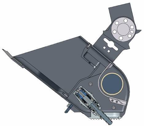
Section titled “Rasp qualification”Ground qualification of the engineering-model ISAD in a thermal vacuum chamber, using JSC Mars-1 with water ice, the same with embedded basalt fragments, and pure ice, measured 60 to 80 percent transfer efficiency [3] moving rasp cuttings from the rear to the front chamber. Average rasp cutting duration was 16 s in icy soil and grew to 37 s after 60 minutes of simulated operational life as the tungsten carbide bit wore [3].
Mechanism, thermal and avionics
Section titled “Mechanism, thermal and avionics”The rasp bit sits in a pivoting, spring-loaded housing that retracts when the scoop is preloaded and protrudes during cutting, with a knurled contact plate that grips icy soil [3]. Driving the housing against its lower hard stop once per revolution makes the rasp a vibrator that moves cuttings from rear to front chamber [3]. The thermal requirement was to warm actuators to -55 C within one hour of use (three hours for the wrist), hold them below 85 C through 3.5 hours of daytime operation and tolerate an overnight minimum of -93 C; a mechanical thermostat guarded against a stuck-on wrist heater [9]. Arm software ran on the lander Command and Data Handling computer, with a payload electronics board for motor drive, heater drive, encoder counting and sensor digitization [2]. Processor part and memory size are not published.
Brush breakages in Phoenix qualification life testing at -80 C triggered an independent NASA Engineering and Safety Center review [12]. Environmental loads other than pyroshock were negligible for the brushes: the weakest brush tested had a quasi-static capability of 945 g against a 58 g landing qualification load, and relative brush movement needs peak accelerations above 200 g radial or 75 g axial [12]. Brush motors were chosen over brushless types for Sojourner and the Mars Polar Lander arm because they need no commutation electronics, at the cost of brush wear as the life limit [13]. Testing of 29 Maxon RE016 units at -70 to -80 C returned average lifetimes under 10 million revolutions against 30 to 40 million for Sojourner, which forced a change of motor and a silver-graphite brush material; high-load mechanism life then reached 102 million revolutions at -70 C in 1.0 kPa CO2 [13].
Control and operations
Section titled “Control and operations”Arm software expands single commands such as dig a trench into motion sequences, tracks time and energy and ends an activity when allocations are exceeded. Contact is handled by guarded moves against motor current and computed joint torque thresholds, used for TECP insertion, rasp load plate preload, sample acquisition and trenching. Faults, meaning hardware failures, are distinguished from events, meaning any other cause of an incomplete command such as a rock in the path [4]. A surface accommodation algorithm adjusts the scoop trajectory when motion is impeded and, if necessary, dumps and re-executes the dig; autonomous recovery from these events was enabled in flight and saved sols that would otherwise have gone to recovery [4].
Ground planning is the other half of the arm’s autonomy. Operations were planned in the Rover Sequencing and Visualization Program, with target designation from panoramas, collision checking and duration estimation [2]. Each delivery used a Robotic Arm Camera image overlaid on a Payload Interoperability Testbed image so the operator could correct positioning before the dump [4]. Before terrain contact the camera imaged the three lander footpads [2], and it imaged the MECA and TEGA inlets before and after delivery [7].
What is not established
Section titled “What is not established”- Sample counts. The flight operations paper reports 17 samples delivered [4], while the results paper reports 31 acquired and delivered over 152 sols [1]. Neither reconciles the two.
- Quantified arm performance. The flight operations paper gives no placement accuracy, repeatability, force or torque figures, reports hardness as motion-impeded events rather than measured resistance, and gives no denominator of attempts for delivery success except for icy soil [4].
- Soil strength. Strength values are inferences from motor current and imagery, not penetrometer or shear-cell data, so their uncertainty is set by the force reconstruction [1][23].
- Brush motor root cause. The NESC review did not establish a root cause for two broken-brush motors found without shock exposure, and its 2600 G component-level shock figure comes from MER-era tests on a shared motor lot rather than Phoenix hardware [12].
- Ground-test fidelity for icy transfer. The rasp transfer efficiency and cutting duration figures [3] come from a thermal vacuum chamber. The congealing failure appeared only on Mars, and no cited ground test reproduced Mars pressure, sample temperature and solar flux together.
- Successor performance. Every figure cited for Icebreaker, Dual-Rasp, COLDArm, ARIEL and the Matanuska demonstration comes from proposals, development reports or Earth tests; none has been flown on an icy target [11][20][21][28][33].
- Processor and memory. The arm’s computing resources are not published [2].
References
- Arvidson, R. E., Bonitz, R. G., Robinson, M. L., Carsten, J. L., Volpe, R. A., Trebi-Ollennu, A., Mellon, M. T., Chu, P. C., Davis, K. R., Wilson, J. J., Shaw, A. S., Greenberger, R. N., Siebach, K. L., Stein, T. C., Cull, S. C., Goetz, W., Morris, R. V., Ming, D. W., Keller, H. U., Lemmon, M. T., Sizemore, H. G. and Mehta, M. (2009). Results from the Mars Phoenix Lander Robotic Arm experiment
. Journal of Geophysical Research: Planets. Source
BibTeX
@article{arvidson2009results, title = {Results from the Mars Phoenix Lander Robotic Arm experiment}, author = {Arvidson, Raymond E. and Bonitz, Robert G. and Robinson, Matthew L. and Carsten, J. L. and Volpe, Richard A. and Trebi-Ollennu, Ashitey and Mellon, M. T. and Chu, P. C. and Davis, K. R. and Wilson, J. J. and Shaw, A. S. and Greenberger, R. N. and Siebach, K. L. and Stein, T. C. and Cull, S. C. and Goetz, Walter and Morris, Richard V. and Ming, D. W. and Keller, Horst Uwe and Lemmon, Mark T. and Sizemore, H. G. and Mehta, M.}, journal = {Journal of Geophysical Research: Planets}, volume = {114}, pages = {E00E02}, publisher = {American Geophysical Union (AGU)}, year = {2009}, doi = {10.1029/2009je003408}, abstract = {The Mars Phoenix Lander was equipped with a 2.4 m Robotic Arm (RA) with an Icy Soil Acquisition Device capable of excavating trenches in soil deposits, grooming hard icy soil surfaces with a scraper blade, and acquiring icy soil samples using a rasp tool. A camera capable of imaging the scoop interior and a thermal and electrical conductivity probe were also included on the RA. A dozen trench complexes were excavated at the northern plains landing site and 31 samples (including water‐ice‐bearing soils) were acquired for delivery to instruments on the Lander during the 152 sol mission. Deliveries included sprinkling material from several centimeters height to break up cloddy soils on impact with instrument portals. Excavations were done on the side of the Humpty Dumpty and the top of the Wonderland polygons, and in nearby troughs. Resistive forces encountered during backhoe operations show that soils above the 3–5 cm deep icy soil interfaces are stronger with increasing depth. Further, soils are similar in appearance and properties to the weakly cohesive crusty and cloddy soils imaged and excavated by the Viking Lander 2, which also landed on the northern plains. Adsorbed H 2 O is inferred to be responsible for the variable nature and cohesive strength of the soils. Backhoe blade chatter marks on excavated icy soil surfaces, combined with rasp motor currents, are consistent with laboratory experiments using grain‐supported icy soil deposits, as is the relatively rapid decrease in icy soil strength over time as the ice sublimated on Mars.} } - Bonitz, R., Slostad, J., Bon, B., Braun, D., Brill, R., Buck, C. W., Fleischner, R., Haldeman, A., Herman, J., Hertzel, M., Noon, D. E., Pixler, G., Schenker, P., Ton, T., Tucker, C. and Zimmerman, W. (2000). MVACS Robotic Arm
. JPL Open Repository. Source
BibTeX
@inproceedings{bonitz2000mvacs, title = {MVACS Robotic Arm}, author = {Bonitz, R. and Slostad, J. and Bon, Bruce and Braun, D. and Brill, R. and Buck, Carl W. and Fleischner, Richard and Haldeman, A. and Herman, J. and Hertzel, M. and Noon, Don E. and Pixler, G. and Schenker, P. and Ton, T. and Tucker, Curtis and Zimmerman, Wayne}, publisher = {JPL Open Repository}, year = {2000}, url = {https://dataverse.jpl.nasa.gov/dataset.xhtml?persistentId=hdl:2014/13866} } - Bonitz, R. G., Shiraishi, L., Robinson, M., Arvidson, R. E., Chu, P. C., Wilson, J. J., Davis, K. R., Paulsen, G., Kusack, A. G., Archer, D. and Smith, P. (2008). NASA Mars 2007 Phoenix Lander Robotic Arm and Icy Soil Acquisition Device
. Journal of Geophysical Research: Planets. Source
BibTeX
@article{bonitz2008nasa, title = {NASA Mars 2007 Phoenix Lander Robotic Arm and Icy Soil Acquisition Device}, author = {Bonitz, Robert G. and Shiraishi, Lori and Robinson, Matthew and Arvidson, Raymond E. and Chu, P. C. and Wilson, J. J. and Davis, K. R. and Paulsen, G. and Kusack, A. G. and Archer, Doug and Smith, Peter}, journal = {Journal of Geophysical Research: Planets}, volume = {113}, pages = {E00A01}, publisher = {American Geophysical Union (AGU)}, year = {2008}, doi = {10.1029/2007je003030}, abstract = {The primary purpose of the Mars 2007 Phoenix Lander Robotic Arm (RA) and associated Icy Soil Acquisition Device (ISAD) is to acquire samples of Martian dry and icy soil (DIS) by digging, scraping, and rasping, and delivering them to the Thermal Evolved Gas Analyzer and the Microscopy, Electrochemistry, and Conductivity Analyzer. The RA will also position (1) the Thermal and Electrical Conductivity Probe (TECP) in the DIS; (2) the TECP at various heights above the surface for relative humidity measurements, and (3) the Robotic Arm Camera to take images of the surface, trench, DIS samples within the ISAD scoop, magnetic targets, and other objects of scientific interest within its workspace. The RA/ISAD will also be used to generate DIS piles for monitoring; conduct DIS scraping, penetration, rasping, and chopping experiments; perform compaction tests; and conduct trench cave‐in experiments. Data from the soil mechanics experiments will yield information on Martian DIS properties such as angle of repose, cohesion, bearing strength, and grain size distribution.} } - Bonitz, R., Shiraishi, L., Robinson, M., Carsten, J., Volpe, R., Trebi-Ollennu, A., Arvidson, R. E., Chu, P. C., Wilson, J. J. and Davis, K. R. (2009). The Phoenix Mars Lander Robotic Arm
. IEEE Aerospace Conference. Source
BibTeX
@inproceedings{bonitz2009phoenix, title = {The Phoenix Mars Lander Robotic Arm}, author = {Bonitz, Robert and Shiraishi, Lori and Robinson, Matthew and Carsten, Joseph and Volpe, Richard and Trebi-Ollennu, Ashitey and Arvidson, Raymond E. and Chu, P. C. and Wilson, J. J. and Davis, K. R.}, booktitle = {IEEE Aerospace Conference}, pages = {1-12}, organization = {Jet Propulsion Laboratory, California Institute of Technology}, address = {Big Sky, Montana}, year = {2009}, doi = {10.1109/aero.2009.4839306}, abstract = {The Phoenix Mars Lander Robotic Arm (RA) has operated for 149 sols since the Lander touched down on the north polar region of Mars on May 25, 2008. During its mission it has dug numerous trenches in the Martian regolith, acquired samples of Martian dry and icy soil, and delivered them to the Thermal Evolved Gas Analyzer (TEGA) and the Microscopy, Electrochemistry, and Conductivity Analyzer (MECA). The RA inserted the Thermal and Electrical Conductivity Probe (TECP) into the Martian regolith and positioned it at various heights above the surface for relative humidity measurements. The RA was used to point the Robotic Arm Camera to take images of the surface, trenches, samples within the scoop, and other objects of scientific interest within its workspace. Data from the RA sensors during trenching, scraping, and trench cave-in experiments have been used to infer mechanical properties of the Martian soil. This paper describes the design and operations of the RA as a critical component of the Phoenix Mars Lander necessary to achieve the scientific goals of the mission.} } - Chevrier, V. F., Hanley, J. and Altheide, T. S. (2009). Stability of perchlorate hydrates and their liquid solutions at the Phoenix landing site, Mars
. Geophysical Research Letters. Source
BibTeX
@article{chevrier2009stability, title = {Stability of perchlorate hydrates and their liquid solutions at the Phoenix landing site, Mars}, author = {Chevrier, Vincent F. and Hanley, Jennifer and Altheide, Travis S.}, journal = {Geophysical Research Letters}, volume = {36}, year = {2009}, doi = {10.1029/2009gl037497}, abstract = {We studied the low‐temperature properties of sodium and magnesium perchlorate solutions as potential liquid brines at the Phoenix landing site. We determined their theoretical eutectic values to be 236 ± 1 K for 52 wt% sodium perchlorate and 206 ± 1 K for 44.0 wt% magnesium perchlorate. Evaporation rates of solutions at various concentrations were measured under martian conditions, and range from 0.07 to 0.49 mm h −1 for NaClO 4 and from 0.06 to 0.29 mm h −1 for Mg(ClO 4 ) 2 . The extrapolation to Phoenix landing site conditions using our theoretical treatment shows that perchlorates are liquid during the summer for at least part of the day, and exhibit very low evaporation rates. Moreover, magnesium perchlorate eutectic solutions are thermodynamically stable over vapour and ice during a few hours a day. We conclude that liquid brines may be present and even stable for short periods of time at the Phoenix landing site.} } - Grotzinger, J. P., Crisp, J., Vasavada, A. R., Anderson, R. C., Baker, C. J., Barry, R., Blake, D. F., Conrad, P., Edgett, K. S., Ferdowski, B., Gellert, R., Gilbert, J. B., Golombek, M., Gómez-Elvira, J., Hassler, D. M., Jandura, L., Litvak, M., Mahaffy, P., Maki, J., Meyer, M., Malin, M. C., Mitrofanov, I., Simmonds, J. J., Vaniman, D., Welch, R. V. and Wiens, R. C. (2012). Mars Science Laboratory Mission and Science Investigation
. Space Science Reviews. Source
BibTeX
@article{grotzinger2012mars, title = {Mars Science Laboratory Mission and Science Investigation}, author = {Grotzinger, John P. and Crisp, J. and Vasavada, Ashwin R. and Anderson, R. C. and Baker, C. J. and Barry, R. and Blake, David F. and Conrad, P. and Edgett, Kenneth S. and Ferdowski, B. and Gellert, Ralf and Gilbert, J. B. and Golombek, M. and Gómez-Elvira, J. and Hassler, Donald M. and Jandura, Louise and Litvak, Maxim and Mahaffy, P. and Maki, J. and Meyer, M. and Malin, Michal C. and Mitrofanov, Igor and Simmonds, John J. and Vaniman, D. and Welch, R. V. and Wiens, Roger C.}, journal = {Space Science Reviews}, volume = {170}, pages = {5--56}, year = {2012}, doi = {10.1007/978-1-4614-6339-9_3}, abstract = {Scheduled to land in August of 2012, the Mars Science Laboratory (MSL) Mission was initiated to explore the habitability of Mars. This includes both modern environments as well as ancient environments recorded by the stratigraphic rock record preserved at the Gale crater landing site. The Curiosity rover has a designed lifetime of at least one Mars year (∼23 months), and drive capability of at least 20 km. Curiosity’s science payload was specifically assembled to assess habitability and includes a gas chromatograph-mass spectrometer and gas analyzer that will search for organic carbon in rocks, regolith fines, and the atmosphere (SAM instrument); an x-ray diffractometer that will determine mineralogical diversity (CheMin instrument); focusable cameras that can image landscapes and rock/regolith textures in natural color (MAHLI, MARDI, and Mastcam instruments); an alpha-particle x-ray spectrometer for in situ determination of rock and soil chemistry (APXS instrument); a laser-induced breakdown spectrometer to remotely sense the chemical composition of rocks and minerals (ChemCam instrument); an active neutron spectrometer designed to search for water in rocks/regolith (DAN instrument); a weather station to measure modern-day environmental variables (REMS instrument); and a sensor designed for continuous monitoring of background solar and cosmic radiation (RAD instrument). The various payload elements will work together to detect and study potential sampling targets with remote and in situ measurements; to acquire samples of rock, soil, and atmosphere and analyze them in onboard analytical instruments; and to observe the environment around the rover. The 155-km diameter Gale crater was chosen as Curiosity’s field site based on several attributes: an interior mountain of ancient flat-lying strata extending almost 5 km above the elevation of the landing site; the lower few hundred meters of the mountain show a progression with relative age from clay-bearing to sulfate-bearing strata, separated by an unconformity from overlying likely anhydrous strata; the landing ellipse is characterized by a mixture of alluvial fan and high thermal inertia/high albedo stratified deposits; and a number of stratigraphically/geomorphically distinct fluvial features. Samples of the crater wall and rim rock, and more recent to currently active surface materials also may be studied. Gale has a well-defined regional context and strong evidence for a progression through multiple potentially habitable environments. These environments are represented by a stratigraphic record of extraordinary extent, and insure preservation of a rich record of the environmental history of early Mars. The interior mountain of Gale Crater has been informally designated at Mount Sharp, in honor of the pioneering planetary scientist Robert Sharp. The major subsystems of the MSL Project consist of a single rover (with science payload), a Multi-Mission Radioisotope Thermoelectric Generator, an Earth-Mars cruise stage, an entry, descent, and landing system, a launch vehicle, and the mission operations and ground data systems. The primary communication path for downlink is relay through the Mars Reconnaissance Orbiter. The primary path for uplink to the rover is Direct-from-Earth. The secondary paths for downlink are Direct-to-Earth and relay through the Mars Odyssey orbiter. Curiosity is a scaled version of the 6-wheel drive, 4-wheel steering, rocker bogie system from the Mars Exploration Rovers (MER) Spirit and Opportunity and the Mars Pathfinder Sojourner. Like Spirit and Opportunity, Curiosity offers three primary modes of navigation: blind-drive, visual odometry, and visual odometry with hazard avoidance. Creation of terrain maps based on HiRISE (High Resolution Imaging Science Experiment) and other remote sensing data were used to conduct simulated driving with Curiosity in these various modes, and allowed selection of the Gale crater landing site which requires climbing the base of a mountain to achieve its primary science goals. The Sample Acquisition, Processing, and Handling (SA/SPaH) subsystem is responsible for the acquisition of rock and soil samples from the Martian surface and the processing of these samples into fine particles that are then distributed to the analytical science instruments. The SA/SPaH subsystem is also responsible for the placement of the two contact instruments (APXS, MAHLI) on rock and soil targets. SA/SPaH consists of a robotic arm and turret-mounted devices on the end of the arm, which include a drill, brush, soil scoop, sample processing device, and the mechanical and electrical interfaces to the two contact science instruments. SA/SPaH also includes drill bit boxes, the organic check material, and an observation tray, which are all mounted on the front of the rover, and inlet cover mechanisms that are placed over the SAM and CheMin solid sample inlet tubes on the rover top deck.} } - Keller, H. U., Goetz, W., Hartwig, H., Hviid, S. F., Kramm, R., Markiewicz, W. J., Reynolds, R., Shinohara, C., Smith, P., Tanner, R., Woida, P., Woida, R., Bos, B. J. and Lemmon, M. T. (2008). Phoenix Robotic Arm Camera
. The International Journal of Robotics Research. Source
BibTeX
@article{keller2008phoenix, title = {Phoenix Robotic Arm Camera}, author = {Keller, Horst Uwe and Goetz, Walter and Hartwig, H. and Hviid, S. F. and Kramm, R. and Markiewicz, W. J. and Reynolds, R. and Shinohara, C. and Smith, P. and Tanner, R. and Woida, P. and Woida, R. and Bos, Brent J. and Lemmon, Mark T.}, journal = {The International Journal of Robotics Research}, volume = {113}, pages = {E00A17}, publisher = {American Geophysical Union (AGU)}, year = {2008}, doi = {10.1029/2007je003044}, abstract = {The Phoenix Robotic Arm Camera (RAC) is a variable‐focus color camera mounted to the Robotic Arm (RA) of the Phoenix Mars Lander. It is designed to acquire both close‐up images of the Martian surface and microscopic images (down to a scale of 23 μ m/pixel) of material collected in the RA scoop. The mounting position at the end of the Robotic Arm allows the RAC to be actively positioned for imaging of targets not easily seen by the Stereo Surface Imager (SSI), such as excavated trench walls and targets under the Lander structure. Color information is acquired by illuminating the target with red, green, and blue light‐emitting diodes. Digital terrain models (DTM) can be generated from RAC images acquired from different view points. This can provide high‐resolution stereo information about fine details of the trench walls. The large stereo baseline possible with the arm can also provide a far‐field DTM. The primary science objectives of the RAC are the search for subsurface soil/ice layering at the landing site and the characterization of scoop samples prior to delivery to other instruments on board Phoenix. The RAC shall also provide low‐resolution panoramas in support of SSI activities and acquire images of the Lander deck for instrument and Lander check out. The camera design was inherited from the unsuccessful Mars Polar Lander mission (1999) and further developed for the (canceled) Mars Surveyor 2001 Lander (MSL01). Extensive testing and partial recalibration qualified the MSL01 RAC flight model for integration into the Phoenix science payload.} } - Lee, C.-J. and Tsuyuki, G. (2006). The thermal design evolution of the Phoenix Robotic Arm. doi.org/10.4271/2006-01-2033
BibTeX
@misc{lee2006thermal, title = {The thermal design evolution of the Phoenix Robotic Arm}, author = {Lee, Chern-Jiin and Tsuyuki, Glenn}, howpublished = {Presentation at the SAE Technical Paper Series}, volume = {1}, year = {2006}, doi = {10.4271/2006-01-2033}, abstract = {<div class="htmlview paragraph">Phoenix, NASA's first Mars Scouts mission, will be launched in 2007 and will soft-land inside the Martian Arctic Circle, between north 65° and 72° North latitude, in 2008 to study the water history and to search for habitable zones. Similar to the IDD (Instrument Deployment Device) on the Mars Exploration Rovers (MER), Phoenix has a Robotic Arm (RA) which is equipped with a scoop to dig into the icy soil and to deliver the soil samples to instruments for scientific observations and measurements. As with MER, the actuators and the bearings of the Phoenix RA in a non-operating condition can survive the cold Martian night without any electrical power or any thermal insulation. The RA actuators have a minimum operating allowable flight temperature (AFT) limit of -55°C, so, warm-up heaters are required to bring the temperatures of all the RA actuators above the operating AFT limit prior to early morning operation. The complications of sizing the warm-up heaters of RA actuators, especially the wrist actuator, include the wide range of thermal environments experienced by the arm, the available heater locations that are constrained by the mechanical design, and the warm-up duration requirements. In spite of these challenges, a feasible RA warm-up heater design was achieved which satisfied all the requirements with minimal operational complexity. This paper presents the evolution of the warm-up heater design and the design implementation.</div>} } - Maimone, M. (2016). What drives Curiosity? Robotics technologies on the Mars Science Laboratory. ntrs.nasa.gov/citations/20210007835
BibTeX
@misc{maimone2016what, title = {What drives Curiosity? Robotics technologies on the Mars Science Laboratory}, author = {Maimone, Mark}, year = {2016}, url = {https://ntrs.nasa.gov/citations/20210007835}, abstract = {UNKNOWN} } - McKay, C. P., Stoker, C. R., Glass, B. J., Davé, A. I., Davila, A. F., Heldmann, J. L., Marinova, M. M., Fairen, A. G., Quinn, R. C., Zacny, K. A., Paulsen, G., Smith, P. H., Parro, V., Andersen, D. T., Hecht, M. H., Lacelle, D. and Pollard, W. H. (2013). The Icebreaker Life Mission to Mars: A Search for Biomolecular Evidence for Life
. Astrobiology, 4. Source
BibTeX
@article{mckay2013icebreaker, title = {The {Icebreaker} {Life} {Mission} to {Mars}: A Search for Biomolecular Evidence for Life}, author = {McKay, Christopher P. and Stoker, Carol R. and Glass, Brian J. and Davé, Arwen I. and Davila, Alfonso F. and Heldmann, Jennifer L. and Marinova, Margarita M. and Fairen, Alberto G. and Quinn, Richard C. and Zacny, Kris A. and Paulsen, Gale and Smith, Peter H. and Parro, Victor and Andersen, Dale T. and Hecht, Michael H. and Lacelle, Denis and Pollard, Wayne H.}, journal = {Astrobiology}, volume = {13}, number = {4}, pages = {334--353}, year = {2013}, doi = {10.1089/ast.2012.0878}, abstract = {The search for evidence of life on Mars is the primary motivation for the exploration of that planet. The results from previous missions, and the Phoenix mission in particular, indicate that the ice-cemented ground in the north polar plains is likely to be the most recently habitable place that is currently known on Mars. The near-surface ice likely provided adequate water activity during periods of high obliquity, ∼5 Myr ago. Carbon dioxide and nitrogen are present in the atmosphere, and nitrates may be present in the soil. Perchlorate in the soil together with iron in basaltic rock provides a possible energy source for life. Furthermore, the presence of organics must once again be considered, as the results of the Viking GCMS are now suspect given the discovery of the thermally reactive perchlorate. Ground ice may provide a way to preserve organic molecules for extended periods of time, especially organic biomarkers. The Mars Icebreaker Life mission focuses on the following science goals: (1) Search for specific biomolecules that would be conclusive evidence of life. (2) Perform a general search for organic molecules in the ground ice. (3) Determine the processes of ground ice formation and the role of liquid water. (4) Understand the mechanical properties of the martian polar ice-cemented soil. (5) Assess the recent habitability of the environment with respect to required elements to support life, energy sources, and possible toxic elements. (6) Compare the elemental composition of the northern plains with midlatitude sites. The Icebreaker Life payload has been designed around the Phoenix spacecraft and is targeted to a site near the Phoenix landing site. However, the Icebreaker payload could be supported on other Mars landing systems. Preliminary studies of the SpaceX Dragon lander show that it could support the Icebreaker payload for a landing either at the Phoenix site or at midlatitudes. Duplicate samples could be cached as a target for possible return by a Mars Sample Return mission. If the samples were shown to contain organic biomarkers, interest in returning them to Earth would be high. Key Words: In situ measurement—Life detection—Mars—Planetary protection—Special region. Astrobiology 13, 334–353.} } - McManamen, J. P., Pellicciotti, J. W., De Kramer, C., Dube, M. J., Peeler, D., Muirhead, B. K., Sevilla, D. R., Sabahi, D. and Knopp, M. D. (2007). Independent Review Support for Phoenix Mars Mission Robotic Arm Brush Motor Failure
. NASA, NASA/TM-2007-215084, NESC-RP-07-13/06-050-E. Source
BibTeX
@techreport{mcmanamen2007independent, title = {Independent Review Support for Phoenix Mars Mission Robotic Arm Brush Motor Failure}, author = {McManamen, John P. and Pellicciotti, Joseph W. and De Kramer, Cornelis and Dube, Michael J. and Peeler, Deborah and Muirhead, Brian K. and Sevilla, Donald R. and Sabahi, Dara and Knopp, Michael D.}, number = {NASA/TM-2007-215084, NESC-RP-07-13/06-050-E}, institution = {NASA}, year = {2007}, url = {https://ntrs.nasa.gov/citations/20070035083}, abstract = {The Phoenix Project requested the NASA Engineering and Safety Center (NESC) perform an independent peer review of the Robotic Arm (RA) Direct Current (DC) motor brush anomalies that originated during the Mars Exploration Rover (MER) Project and recurred during the Phoenix Project. The request was to evaluate the Phoenix Project investigation efforts and provide an independent risk assessment. This includes a recommendation for additional work and assessment of the flight worthiness of the RA DC motors. Based on the investigation and findings contained within this report, the IRT concurs with the risk assessment Failure Cause / Corrective Action (FC/CA) by the project, "Failure Effect Rating "3"; Major Degradation or Total Loss of Function, Failure Cause/Corrective Action Rating Currently "4"; Unknown Cause, Uncertainty in Corrective Action."} } - Reid, L. K., Braun, D. F. and Noon, D. E. (1999). Robotic Arm and Rover Actuator Systems for Mars Exploration
. Aerospace Mechanisms Symposium. Source
BibTeX
@inproceedings{reid1999robotic, title = {Robotic Arm and Rover Actuator Systems for Mars Exploration}, author = {Reid, Lisa K. and Braun, David F. and Noon, Don E.}, booktitle = {Aerospace Mechanisms Symposium}, organization = {Jet Propulsion Laboratory, California Institute of Technology}, year = {1999}, url = {https://dataverse.jpl.nasa.gov/dataset.xhtml?persistentId=hdl:2014/18020} } - Robinson, M., Collins, C., Leger, P., Carsten, J., Tompkins, V., Hartman, F. and Yen, J. (2013). In-Situ Operations and Planning for the Mars Science Laboratory Robotic Arm: The First 200 Sols
. IEEE International Conference on Systems, Man and Cybernetics. Source
BibTeX
@inproceedings{robinson2013situ, title = {In-Situ Operations and Planning for the Mars Science Laboratory Robotic Arm: The First 200 Sols}, author = {Robinson, Matthew and Collins, Curtis and Leger, Paul and Carsten, Joseph and Tompkins, Vandana and Hartman, Frank and Yen, Jeng}, booktitle = {IEEE International Conference on Systems, Man and Cybernetics}, volume = {tbd}, pages = {153-158}, year = {2013}, doi = {10.1109/sysose.2013.6575259}, abstract = {The Robotic Arm (RA) has operated for more than 200 Martian solar days (or sols) since the Mars Science Laboratory rover touched down in Gale Crater on August 5, 2012. During the first seven months on Mars the robotic arm has performed multiple contact science sols including the positioning of the Alpha Particle X-Ray Spectrometer (APXS) and/or Mars Hand Lens Imager (MAHLI) with respect to rocks or loose regolith targets. The RA has supported sample acquisition using both the scoop and drill, sample processing with CHIMRA (Collection and Handling for In- Situ Martian Rock Analysis), and delivery of sample portions to the observation tray, and the SAM (Sample Analysis at Mars) and CHEMIN (Chemistry and Mineralogy) science instruments. This paper describes the planning and execution of robotic arm activities during surface operations, and reviews robotic arm performance results from Mars to date.} } - Schenker, P. S. (2004). The evolution of Space Robotic Exporation : manipulation, mobility and on-board intelligence. dataverse.jpl.nasa.gov/dataset.xhtml
BibTeX
@misc{schenker2004evolution, title = {The evolution of Space Robotic Exporation : manipulation, mobility and on-board intelligence}, author = {Schenker, Paul S.}, howpublished = {Presentation at the Seminar Presenation at the University of Reading}, year = {2004}, url = {https://dataverse.jpl.nasa.gov/dataset.xhtml?persistentId=hdl:2014/38783} } - Taylor, J., Butman, S., Edwards, C., Ilott, P., Kornfeld, R., Lee, D., Shaffer, S. and Signori, G. (2010). Phoenix Telecommunications
. Jet Propulsion Laboratory, California Institute of Technology, Article 15. Source
BibTeX
@techreport{taylor2010phoenix, title = {Phoenix Telecommunications}, author = {Taylor, Jim and Butman, Stan and Edwards, Chad and Ilott, Peter and Kornfeld, Richard and Lee, Dennis and Shaffer, Scott and Signori, Gina}, series = {DESCANSO Design and Performance Summary Series}, number = {Article 15}, institution = {Jet Propulsion Laboratory, California Institute of Technology}, year = {2010}, url = {https://descanso.jpl.nasa.gov/DPSummary/PhxArticle_--RC101013DocX_COMPRESSED_AcronFixBU.pdf} } - Yahnker, C. R., Brinkman, A., Hendry, M. L., Jasper, J. D., Shiraishi, L. R., Hofmann, A. E., Siegel, K. J. and Tevere, E. L. (2018). Introduction to Tools and Techniques for Surface Sampling on Europa
. ASCE Earth and Space Conference. Source
BibTeX
@inproceedings{yahnker2018introduction,
  title = {Introduction to Tools and Techniques for Surface Sampling on Europa},
  author = {Yahnker, Christopher R. and Brinkman, Alexander and Hendry, Morgan L. and Jasper, Jay D. and Shiraishi, Lori R. and Hofmann, Amy E. and Siegel, Katherine J. and Tevere, Erica L.},
  booktitle = {ASCE Earth and Space Conference},
  pages = {501-511},
  publisher = {American Society of Civil Engineers},
  year = {2018},
  doi = {10.1061/9780784481899.048},
  abstract = {The NASA Jet Propulsion Laboratory (JPL) is studying excavation and collection of a sample from an icy surface for a potential landed mission to Europa. Europa presents unique challenges in planetary sampling. Very little is known about the local topography and material composition of the surface. The environmental conditions of being cryogenically cold (80-130 K), low gravity (~1/7th Earth), no atmosphere, low lighting conditions, and limited ground in the loop opportunities have forced JPL to look at sampling differently than past missions. Interacting with the surface of the Jovian moon requires a sampling system that is robust to local topography on the scale of the lander and/or the tool. In addition, the sampling system must be capable both of detecting faults and automatically adjusting to them to achieve the mission objectives without ground in the loop feedback. Presented here is an overview of a sampling system concept that involves a two-stage approach for collecting a sample. The first stage uses an excavation tool to prepare the surface site for sample collection by removing the top layer of irradiated material and clearing tailings from the hole. The second stage then generates and collects a sample for delivery to instruments on-board a lander. Also presented is an introduction for how autonomy and sensing technologies might be employed to enable mission success.}
}
Further reading
- (2017). NASA Science: Phoenix. science.nasa.gov/mission/mars-phoenix