Dragonfly
Program pages JHUAPL: Dragonfly Spacecraft and Science Payload
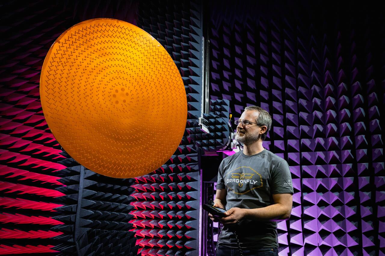 NASA/Johns Hopkins APL.
Overview
Section titled “Overview”Dragonfly is a nuclear-powered eight-rotor lander built for Saturn’s moon Titan, selected in June 2019 as NASA’s fourth New Frontiers mission [5]. It is managed and built by the Johns Hopkins University Applied Physics Laboratory, with Elizabeth Turtle as principal investigator. As of mid-2025 the project had passed its mission critical design review and was entering integration and test.
The design premise is that Titan’s scientifically interesting environments are spatially separated, so a fixed lander cannot sample the moon’s chemical and geological diversity [5]. Dragonfly is therefore best described not as an aircraft but as a relocatable lander with repeatable flight capability: it spends most of its time on the ground doing landed science, and flies roughly once per one to two Titan days, that is every 16 to 32 Earth days, to reach a new site.
Specifications
Section titled “Specifications”| Parameter | Value | Source |
|---|---|---|
| Mass | about 875 kg | [4], [12] |
| Dimensions | about 3.85 x 3.85 x 1.75 m | [4], [12] |
| Structure | aluminum panels and interior decks, aluminum honeycomb fuselage skin, polymethacrylimide foam covering | [12] |
| Rotors | 8 fixed-pitch, 1.35 m diameter, four counter-rotating coaxial pairs in an X8 layout | [5], [7], [12] |
| Control | differential motor speed only, no cyclic or collective pitch | [5], [7] |
| Rotor speed range on Titan | 500 to 1100 RPM | [7] |
| Rotor-out tolerance | at least one rotor or motor | [1] |
| Power source | radioisotope thermoelectric generator, 70 W | [1] |
| Telecom | high-gain and medium-gain antennas, 100 W traveling-wave tube amplifier, APL Frontier radio, X-band only | [12] |
Mission profile
Section titled “Mission profile”| Parameter | Value | Source |
|---|---|---|
| Selection | NASA New Frontiers 4, June 2019 | [5] |
| Launch | planned 2028, Falcon Heavy | [3], [5], [6] |
| Titan arrival | 2034, after a cruise of nearly seven years | [3], [5], [6] |
| Science mission duration | more than three years | [5], [6] |
| Landing region | the 80 km Selk impact crater, at about 7 N | [5], [6] |
| Flight cadence | roughly once per one to two Titan days, that is every 16 to 32 Earth days | [5] |
| Surface daily cycle | about 3 to 4 h of telecom against about 20 h of hibernation | [5] |
Mobility
Section titled “Mobility”Titan is the only body in the solar system where rotorcraft flight is straightforwardly easier than on Earth. Surface atmospheric density is 5.4 kg/m3, about four times Earth sea level air, at a pressure of 1.47 bar and a temperature of 94 K, while surface gravity is 1.35 m/s2, about one seventh of Earth’s [1], [8]. Rotor thrust scales with density and disk area while weight scales with gravity, so the combination gives a flight power for a given vehicle mass about 40 times lower than on Earth. The low temperature also lowers molecular viscosity to roughly 6e-6 Pa s, about three times below Earth air, so the 1.35 m rotors of Dragonfly operate at Reynolds numbers characteristic of much larger terrestrial rotors [1]. This is the opposite of the Mars case, where a thin atmosphere forces very low Reynolds numbers, very high tip speeds and a severe mass budget.
Locomotion is by eight fixed-pitch rotors of 1.35 m diameter, arranged as four counter-rotating coaxial pairs in an X8 configuration, one pair on each of four arms attached to the fuselage [5], [7], [12]. Control is entirely by differential motor speed, with no cyclic or collective pitch mechanism [5], [7]. Coaxial pairing balances torque and raises thrust per unit of rotor disk area, which matters because the disk area available is capped by the requirement to stow inside a 4.5 m aeroshell. The octorotor layout carries a small aerodynamic penalty relative to a pure quadrotor but tolerates the loss of at least one rotor or motor [1]. The expected operating speed range on Titan is 500 to 1100 RPM [7]; blade tip Mach number is around 0.4 against a Titan speed of sound of about 194 m/s, so compressibility is not a design driver [1].
The rotors are machined from monolithic bars of aluminum 2219-T851, chosen for well-characterized fatigue performance at cryogenic temperature, then hollowed, closed with electron-beam-welded covers, heat treated and finish machined, with skin thicknesses of about 2.5 mm and integral leading-edge spars [7]. Twist varies from 17.5 degrees at the root to 6.1 degrees at the tip and thickness from 24 percent to 12 percent of chord. The airfoil family was selected for predictable behavior across a wide Reynolds number range and benign stall.
Flight performance analysis for a representative 420 kg vehicle gives a maximum-endurance speed near 8 m/s and a maximum-range speed near 10 m/s, at a flight power a little over 2 kW [1]. Predicted near-surface winds are only 1 to 2 m/s, consistent with Huygens Doppler tracking and boundary-layer measurements at the Huygens landing site [11], so wind has a minor effect on range at a 10 m/s transit speed. The informal early capability target was to fly farther in one hop than any Mars rover had driven in a decade, about 40 km [1]. Flight power scales roughly as mass to the 1.5 power, so vehicle growth costs endurance directly.
The dominant flight-mechanics hazard is the vortex ring state, in which a rotor descending through its own downwash loses thrust and becomes unsteady. This constrains vertical descent: profiling flights are flown with forward motion, climbing or descending at about 20 degrees to the horizontal rather than vertically [1]. The release from the backshell deliberately traverses the windmill brake state and the vortex ring state, and a dedicated transition-to-powered-flight control mode rolls the vehicle about its long axis to escape them, reaching the nominal flight envelope in 18 to 24 seconds [5], [10]. Coaxial rotor behavior through this regime was characterized in full-scale flight-like hardware in the NASA Langley Transonic Dynamics Tunnel using R-134a, whose density of 3.98 kg/m3 is much closer to Titan’s 5.35 kg/m3 than air is, matching Reynolds and tip Mach number simultaneously [7].
On the ground the vehicle rests on two landing skids and can shuffle a few meters to reposition the skid-mounted drills or change a camera viewpoint [1].
Power and energy
Section titled “Power and energy”A single Multi-Mission Radioisotope Thermoelectric Generator supplies all primary power. Solar is not viable: sunlight at Titan’s surface is about 1000 times weaker than at Earth, roughly 100 times from distance and a further factor of about 10 from the haze, and the dense 94 K atmosphere imposes a continuous heat load [1]. The New Frontiers announcement of opportunity permitted up to three MMRTGs, but their mass and their roughly 2 kW of waste heat made a single unit the obvious choice. Anticipated electrical output at Titan, after nine years of plutonium decay and thermoelectric converter degradation from launch, is about 70 W [1].
Flight is battery-buffered rather than direct because the mismatch between supply and demand is about thirty to one: about 70 W available continuously against a flight power of over 2 kW [1]. The MMRTG therefore trickle-charges a battery over days, and the battery discharges over the tens of minutes of a flight [5]. The lander carries a 134 A-h battery [12]. The design study set an upper bound on useful battery size as the capacity that exactly captures the full MMRTG output across a Titan night, 75 W for 192 h or about 14 kWh, which at a representative space-qualified 100 Wh/kg would mass about 140 kg; in practice a smaller battery is flown [1].
The same logic governs the rest of the energy budget. Downlink and flight are the two large consumers; drilling and sample analysis are moderately power-hungry but need only a few hours [1]. Continuous low-power monitoring, meteorology and seismology, actually dominates the payload energy budget over a Titan day, and during those long passive intervals the lander avionics are powered down entirely and only the instrument acquires data, so that battery recharge rate is maximized.
Thermal
Section titled “Thermal”Thermal control is active and centred on reusing MMRTG waste heat rather than rejecting it. A pumped common fluid loop distributes waste heat from the MMRTG through the spacecraft [5]. During cruise the loop transects all three major elements, cruise stage, entry assembly and lander, and excess heat is rejected by radiators on the cruise stage. The loop must be reconfigured twice during entry and descent, first to isolate the cruise stage before its separation and again before lander release, and phase change material in the backshell provides additional regulation during the long descent. On Titan the mode changes from conduction-dominated in vacuum to convection-dominated in the dense cold atmosphere [12].
The vehicle body carries thick insulation around its main electronics box in the manner of the Huygens probe, and tapped MMRTG heat holds that interior, and particularly the battery, at benign temperatures [1]. The design also exploits the cold where it helps: the DraGNS gamma-ray detector is mounted outside the warm box so that the dense 94 K atmosphere cools it to its operating temperature without a mechanical cryocooler.
Cryogenic temperature drives mechanism design. After the first landing the rotor motors are held at fixed position and their heaters powered off so that the bearing lubricant freezes, after which power is removed; the frozen lubricant prevents wind gusts from turning the rotors [5]. Window de-icing heaters are run before entry so that ice melted by entry heating inside the aeroshell cannot condense and refreeze on instrument windows. Navigation camera heaters are activated when heatshield separation exposes the lander to the atmosphere.
Compute and avionics
Section titled “Compute and avionics”The lander houses the flight computers that run the flight software for entry, descent and first flight, and operates dual string during the critical sequence: the non-prime single board computer is powered up before entry specifically to ensure dual-string operation, and hibernation and safe-mode fault response are disabled for the whole EDL sequence [5], [9]. Sensing for flight comprises two inertial measurement units, a lidar, navigation cameras and pressure sensors. Star trackers and a blow-down propulsion system serve attitude control before atmospheric entry only. The IMUs need about two hours to reach thermal stability, which is what sets the length of the entry preparation period. A solid-state recorder preserves navigation imagery and lidar relief maps across hibernation periods for later downlink. The processor type, memory and radiation tolerance approach are not stated in the open literature.
Autonomy
Section titled “Autonomy”Flights are entirely closed loop because of the round-trip light time between Earth and Titan [3], [5]. The Dragonfly link budget is worked at about 10 AU [1]; at that range one-way light time is about 83 minutes, and the Earth-Titan distance over the mission does not fall far below 8.5 AU, or about 71 minutes. No part of a first flight lasting 20 to 40 minutes, and no part of any subsequent flight, can therefore be supervised from the ground [5]. Autonomy is split between two layers.
The upper layer is a rule-based autonomy engine that sequences the mission. For entry and descent it divides an EDL timeline of roughly 350 unique events into about 30 activities, each a series of scripted commands whose start times are governed by timeline constraints sized to absorb nearly 1000 seconds of uncertainty in total descent time [5], [9]. Most entry and descent activity is run open loop on this engine; the engine also handles the prioritization, override and buffering logic for status tone transmission.
The lower layer is the mobility guidance, navigation and control software, which is distinct from the cruise guidance and control software and takes over primary responsibility 420 seconds before entry interface [5], [10]. Its navigation filter fuses IMU data with lander pressure sensors, lidar altimetry and navigation camera velocimetry. Two terrain-sensing algorithm sets run on top of it. Lidar terrain sensing takes push-broom scan data, builds a three-dimensional relief map, and identifies hazards, primarily rocks taller than 25 cm and slopes steeper than 10 degrees, then ranks candidate safe sites of at least 10 m radius by relative probability of safe touchdown [5]. Electro-optical terrain sensing processes navigation camera imagery for velocimetry and saves images along the search track into a breadcrumb buffer; correlating live imagery against tagged reference breadcrumbs gives terrain-relative optical navigation back to a site the vehicle has already flown over and assessed.
The first flight exercises the full chain: transition to powered flight, descent to a search altitude of about 110 m, level forward flight on a northerly heading chosen perpendicular to the local dune orientation to shorten the search, lidar hazard mapping, course reversal onto a selected site under breadcrumb navigation, a steep terminal descent about 10 degrees from vertical to 70 m, then to 20 m at 1 m/s, and a final vertical descent at 0.4 m/s [5], [10]. Sensor use is deliberately truncated near the ground: navigation camera and lidar data stop being ingested at 20 m because of expected rotor-induced brownout, pressure altimetry stops at 5 m because of ground-effect dynamic pressure perturbation, and the last 5 m are flown on IMU data alone with a touchdown detector based on vertical velocity error.
For the surface mission the concept of operations reduces autonomy risk by staging it. Mobility is exercised progressively: first a hop of a few seconds within terrain already known from descent and panoramic imaging, then flights of increasing duration and range that return to the original known-safe site, with early hops on inertial guidance alone and optical navigation used only after in-flight image quality and landmark abundance at Titan have been verified [1]. Thereafter a leapfrog pattern is used, in which the vehicle overflies and senses a candidate zone at distance R/3 or 2R/3, returns or lands at the previously certified zone, and only commits to a new site after ground analysis of the sensor data confirms it.
Communications
Section titled “Communications”All communication is direct to Earth through the Deep Space Network; there is no relay orbiter, which is what constrains the mission to low latitudes where Earth is visible from the surface [1], [12]. The link uses a high-gain antenna, a medium-gain antenna, a 100 W traveling-wave tube amplifier and an APL-designed Frontier radio operating in X-band only. The high-gain antenna is stowed flat during flight, behind an aerodynamic fairing ahead of its gimbal [1]. Surface operations follow a daily cycle of roughly three to four hours of telecom against about twenty hours of hibernation [5].
The energy argument that sets the link is instructive. High-gain missions require empirically about 5 mJ per bit per astronomical unit to acquire and send science data; Huygens returned about 100 MB over roughly 3.5 h at 8 kbps via Cassini relay, and a hundredfold improvement to 10 GB at about 10 AU would need roughly 0.5 GJ, or 140 kWh, which is far beyond any practical stored-energy system and is the direct argument for radioisotope power [1]. Mission data return therefore scales with mission duration, not with peak capability. Specific downlink data rates are not stated in the open literature.
During entry and descent the strategy is different: only multiple frequency shift keying tones are sent, each broadcast for 60 seconds to maximize the chance of detection, through three antennas in succession as the vehicle sheds elements [5]. Transmission is inhibited for about 20 minutes across entry to protect the single-string telecom from corona, and X band suffers roughly 70 seconds of ionization blackout around peak heating; the traveling-wave tube is also placed in standby across every pyrotechnic event as a shock precaution and may be cycled to manage its own temperature.
Payload and instruments
Section titled “Payload and instruments”Five instruments plus an engineering investigation [5], [6]:
- DraMS, the Dragonfly Mass Spectrometer, from NASA GSFC. A linear ion trap derived from SAM on Curiosity and MOMA on ExoMars, operating in laser desorption, gas chromatography and atmospheric enrichment modes, measuring molecular masses up to about 2000 Da in surface and atmospheric samples [6].
- DraGNS, the Dragonfly Gamma-Ray and Neutron Spectrometer, from APL and Goddard. A pulsed neutron generator interrogates the surface within 2 m of the lander to give bulk elemental composition of the shallow subsurface, including C, H, N, O, Na, Mg, P, S, Cl and K. Its value is operational as much as scientific: it establishes what a site is made of without any sample handling, so the team can decide whether to spend drilling and analysis energy there at all [1].
- DraGMet, the Dragonfly Geophysics and Meteorology package, from APL. Eleven measured properties: atmospheric temperature, pressure, wind speed and direction, methane humidity, hydrogen partial pressure, crustal seismicity, electric field, surface dielectric properties, surface temperature and ambient sound [6]. Methane humidity is sensed by differential near-infrared absorption, and wind sensors are placed outboard of each rotor hub to keep them clear of the MMRTG thermal plume [1]. It is a low-power continuous instrument, which is why it dominates the payload energy budget over a Titan day.
- DragonCam, the Dragonfly camera suite. Eight science cameras: two panoramic cameras mounted on the high-gain antenna and pointed with it, two fixed forward-looking cameras, two wide-angle downward workspace cameras boresighted on the left and right sampling sites, and two microscopic imagers at 60 micrometer pixels focused on the material to be ingested [6].
- DrACO, the Drill for Acquisition of Complex Organics, from Honeybee Robotics. Not a science instrument but the sample chain, described below [1], [6].
- DrEAM, the Dragonfly Entry Aerosciences Measurement suite, an engineering investigation collecting pressure, temperature and heat flux data on the heatshield and backshell during entry [5].
The navigation lidar and navigation cameras are engineering sensors but also yield terrain relief maps that are preserved for downlink [5].
The sample acquisition architecture is a direct consequence of the environment. A sampling arm of the Viking, Phoenix or MSL type was traded away as expensive, heavy and a single point of failure; instead two drills with simple one-degree-of-freedom actuators are mounted one in each landing skid, giving both redundancy and a choice of sample [1]. Transport from drill to instrument uses the atmosphere itself: material is conveyed pneumatically by a blower, sucked through a hose and separated in a cyclone before delivery to DraMS at cryogenic temperature [6]. Pneumatic transfer is practical at Titan precisely because the atmosphere is dense, and it removes the articulated scoop-and-transfer mechanism that dominates Mars sampling design.
The rotors themselves are used as an experiment. Controlled saltation studies spin one or more rotors to raise surface particles and monitor the threshold at which grains begin to move, giving a direct measurement of a quantity otherwise inferred from dune morphology [1], [6].
Modes of operation
Section titled “Modes of operation”The surface duty cycle is set by the battery. The nominal daily pattern is roughly three to four hours of telecom and about twenty hours of hibernation [5]. Flights, which are energy-intensive, are separated by one to two Titan days of recharge. Because most science that requires observation, including flight, is best done in daylight, nighttime activity is minimal and power is preferentially devoted to recharging [1]. Activities that are energy-intensive but not light-dependent, such as drilling and sample analysis, can be deferred into the Titan night when excess energy is available, provided the battery is large enough to have captured the MMRTG output.
The entry sequence has five defined sub-phases: entry preparation, ballistic entry, parachute descent, preparation for powered flight, and lander release [5].
| Event | Condition |
|---|---|
| Wake-up from hibernation | entry interface minus 190 min |
| Precession and spin-up to 2 rpm | entry interface minus 38 min |
| Cruise stage separation | entry interface minus 10 min |
| Entry interface | 1270 km altitude, 7.41 km/s, flight path angle -46.8 degrees |
| Peak heating | about 230 W/cm2, at 250 km |
| Peak deceleration | 11 g by requirement, at 224 km |
| Drogue deployment | Mach 1.5, at 145 km |
| Drogue descent | about 105 min |
| Main parachute deployment | barometric, at 5 km pressure altitude |
| Heatshield separation | main deployment plus 2 min |
| Pose maneuver | gravity-driven, translates the lander about 1 m to expose the rotors below the backshell plane |
| Rotor-based yaw despin | about 900 rpm, held within a 3 deg/s deadband |
| Lander release | 906 m above ground level |
About one third of the total entry heat load comes from shock layer radiation from the small methane fraction in the upper atmosphere [9].
Flight modes proper are transition to powered flight, velocity tracking for descent, constant-altitude forward flight under waypoint guidance for site search, a landing mode below 70 m, and a purely vertical mode below 20 m, followed by a post-flight mode and controlled rotor shutdown [5]. Hibernation and safe mode exist but are explicitly inhibited across the critical sequence.
Ground operations
Section titled “Ground operations”Dragonfly is operated by the Johns Hopkins University Applied Physics Laboratory, which also manages and built the mission, with the Jet Propulsion Laboratory performing the navigation role [3], [5]. Because flights are closed loop, the ground role is site selection and certification rather than flight control: the team analyses reconnaissance imagery, lidar relief maps and navigation imagery returned after each flight to designate the next candidate landing zone, and the leapfrog pattern is structured so that a human decision gate sits between sensing a new zone and committing to land in it [1]. Arrival operations are organized around an EDL timeline maintained by a dedicated arrival phase lead, and an EDL tones working group defines which nominal and faulted events warrant a tone [5]. Planning cycle length and the ground tooling used for flight planning are not described in the open literature.
Technologies developed
Section titled “Technologies developed”Dragonfly has not flown, so its legacy is prospective, but several elements are already transferable.
The first is the demonstration that atmospheric density is a resource rather than an obstacle. Pneumatic sample transfer, convective thermal control, aerodynamic braking across 2.5 hours of descent, and rotor-based despin all substitute environmental properties for mechanisms [1], and each removes a moving part from a mission that must survive years at 94 K.
The second is mid-air deployment of a powered aerial vehicle from a parachute-borne backshell, combining an open-loop unguided entry vehicle with an entirely closed-loop aerial mobility system [5]. This is the enabling architecture for proposed Mars rotorcraft delivery, in the same lineage as Ingenuity, and removes the mass of a dedicated landing stage [2].
The third is the characterization of coaxial rotor behavior in and around the vortex ring state at flight scale in a heavy gas, using R-134a to match Reynolds number and tip Mach number simultaneously [7]. That test technique generalizes to any rotorcraft intended for an atmosphere that cannot be reproduced in air.
The fourth is the combination of lidar terrain sensing for hazard mapping with breadcrumb-based terrain-relative optical navigation, which allows a vehicle to certify a landing site by overflight and then return to it without any ground involvement [5]. Nothing in that method is specific to Titan; it applies wherever light time rules out supervision.
References
Section titled “References”References
- Barnes, J. W., Turtle, E. P., Trainer, M. G., Lorenz, R. D., MacKenzie, S. M., Brinckerhoff, W. B., Cable, M. L., Ernst, C. M., Freissinet, C., Hand, K. P., Hayes, A. G., Hörst, S. M., Johnson, J. R., Karkoschka, E., Lawrence, D. J., Le Gall, A., Lora, J. M., McKay, C. P., Miller, R. S., Murchie, S. L., Neish, C. D., Newman, C. E., Núñez, J., Panning, M. P., Parsons, A. M., Peplowski, P. N., Quick, L. C., Radebaugh, J., Rafkin, S. C. R., Shiraishi, H., Soderblom, J. M., Sotzen, K. S., Stickle, A. M., Stofan, E. R., Szopa, C., Tokano, T., Wagner, T., Wilson, C., Yingst, R. A., Zacny, K. and Stähler, S. C. (2021). Science Goals and Objectives for the Dragonfly Titan Rotorcraft Relocatable Lander
. The Planetary Science Journal, 4. Source
BibTeX
@article{barnes2021science, title = {Science Goals and Objectives for the Dragonfly Titan Rotorcraft Relocatable Lander}, author = {Barnes, Jason W. and Turtle, Elizabeth P. and Trainer, Melissa G. and Lorenz, Ralph D. and MacKenzie, Shannon M. and Brinckerhoff, William B. and Cable, Morgan L. and Ernst, Carolyn M. and Freissinet, Caroline and Hand, Kevin P. and Hayes, Alexander G. and Hörst, Sarah M. and Johnson, Jeffrey R. and Karkoschka, Erich and Lawrence, David J. and Le Gall, Alice and Lora, Juan M. and McKay, Christopher P. and Miller, Richard S. and Murchie, Scott L. and Neish, Catherine D. and Newman, Claire E. and Núñez, Jorge and Panning, Mark P. and Parsons, Ann M. and Peplowski, Patrick N. and Quick, Lynnae C. and Radebaugh, Jani and Rafkin, Scot C. R. and Shiraishi, Hiroaki and Soderblom, Jason M. and Sotzen, Kristin S. and Stickle, Angela M. and Stofan, Ellen R. and Szopa, Cyril and Tokano, Tetsuya and Wagner, Thomas and Wilson, Colin and Yingst, R. Aileen and Zacny, Kris and Stähler, Simon C.}, journal = {The Planetary Science Journal}, volume = {2}, number = {4}, pages = {130}, year = {2021}, doi = {10.3847/psj/abfdcf}, abstract = {Abstract NASA’s Dragonfly mission will send a rotorcraft lander to the surface of Titan in the mid-2030s. Dragonfly's science themes include investigation of Titan’s prebiotic chemistry, habitability, and potential chemical biosignatures from both water-based “life as we know it” (as might occur in the interior mantle ocean, potential cryovolcanic flows, and/or impact melt deposits) and potential “life, but not as we know it” that might use liquid hydrocarbons as a solvent (within Titan’s lakes, seas, and/or aquifers). Consideration of both of these solvents simultaneously led to our initial landing site in Titan’s equatorial dunes and interdunes to sample organic sediments and water ice, respectively. Ultimately, Dragonfly's traverse target is the 80 km diameter Selk Crater, at 7° N, where we seek previously liquid water that has mixed with surface organics. Our science goals include determining how far prebiotic chemistry has progressed on Titan and what molecules and elements might be available for such chemistry. We will also determine the role of Titan’s tropical deserts in the global methane cycle. We will investigate the processes and processing rates that modify Titan’s surface geology and constrain how and where organics and liquid water can mix on and within Titan. Importantly, we will search for chemical biosignatures indicative of past or extant biological processes. As such, Dragonfly, along with Perseverance, is the first NASA mission to explicitly incorporate the search for signs of life into its mission goals since the Viking landers in 1976.} } - Chien, S. A., Visentin, G. and Basich, C. (2024). Exploring Beyond Earth using Space Robotics: Update
. Science Robotics. Source
BibTeX
@article{chien2024exploring, title = {Exploring Beyond Earth using Space Robotics: Update}, author = {Chien, Steve A. and Visentin, Gianfranco and Basich, Connor}, journal = {Science Robotics}, publisher = {JPL Open Repository}, year = {2024}, doi = {10.48577/jpl.2ezlhn}, abstract = {Robotic spacecraft enable exploration of our solar system, beyond our human presence. While spacecraft have explored every planet in the solar system, the frontiers of space robotics are at the cutting edge of landers, rovers, and now atmospheric explorers where robotic spacecraft must interact intimately with their environment to explore beyond the reach of flyby and orbital remote sensing.In 2017, we surveyed space robotics - telling the rich history of robotic explorers to the Moon, Mars, and beyond. In this article, we describe the tremendous growth in space robotics missions in the period 2017-2024 with many new entities participating in missions to the surface of the Moon, Mars, and beyond. We also describe the recent development of aerial missions to planets and moons as exemplified by the Ingenuity helicopter on Mars, the Dragonfly mission to Titan, and the planned Sample Recovery Helicopter to Mars. As with the 2017 survey, we seek to provide a big picture of developments and directions in space robotics. Additionally, we focus on sub orbital robotics - landers, rovers, and aerial vehicles, with associated challenges in sensing, manipulation, and mobility.} } - Englander, J. A., Ellison, D. H., Greaves, J., Hatten, N. A., Kennedy, B. M., Jesick, M. C., Lubey, D. P., McQuaide, M. E., Roth, D. C. and Wong, M. C. (2025). Dragonfly Phase C Mission Design and Navigation
. AIAA Infotech @ Aerospace. Source
BibTeX
@inproceedings{englander2025dragonfly, title = {Dragonfly Phase C Mission Design and Navigation}, author = {Englander, Jacob A. and Ellison, Donald H. and Greaves, Jesse and Hatten, Noble A. and Kennedy, Brian M. and Jesick, Mark C. and Lubey, Daniel P. and McQuaide, Maria E. and Roth, Duane C. and Wong, Mau C.}, booktitle = {AIAA Infotech @ Aerospace}, publisher = {JPL Open Repository}, year = {2025}, doi = {10.48577/jpl.l91xgb}, abstract = {Dragonfly is the fourth mission in NASA’s New Frontiers program. Dragonfly is a relocatable octocopter lander that will explore Titan, Saturn’s largest moon. Johns Hopkins University Applied Physics Laboratory (JHUAPL) designs, builds, and operates the spacecraft and performs the Mission Design role, while the Jet Propulsion Laboratory (JPL) performs the Navigation role. Dragonfly will launch in 2028 and arrive at Titan in 2034, with surface operations extending through 2038. This paper describes the state of the Mission Design and Navigation (MDNav) work through mission critical design review in April, 2025.} } - (2026). JHUAPL: Dragonfly Spacecraft and Science Payload. dragonfly.jhuapl.edu/What-Is-Dragonfly/Spacecraft-and-Science-Payload...
BibTeX
@misc{jhuapldragonfly, title = {JHUAPL: Dragonfly Spacecraft and Science Payload}, organization = {dragonfly.jhuapl.edu}, year = {2026}, url = {https://dragonfly.jhuapl.edu/What-Is-Dragonfly/Spacecraft-and-Science-Payload.php} } - Lorenz, R. D., Turtle, E. P., Barnes, J. W., Trainer, M. G., Adams, D. S., Hibbard, K. E., Sheldon, C. Z., Zacny, K., Peplowski, P. N., Lawrence, D. J., Ravine, M. A., McGee, T. G., Sotzen, K. S., MacKenzie, S. M., Langelaan, J. W., Schmitz, S., Wolfarth, L. S. and Bedini, P. D. (2018). Dragonfly: A Rotorcraft Lander Concept for Scientific Exploration at Titan
. Johns Hopkins APL Technical Digest, 3. Source
BibTeX
@article{lorenz2018dragonfly, title = {Dragonfly: A Rotorcraft Lander Concept for Scientific Exploration at Titan}, author = {Lorenz, Ralph D. and Turtle, Elizabeth P. and Barnes, Jason W. and Trainer, Melissa G. and Adams, Douglas S. and Hibbard, Kenneth E. and Sheldon, Colin Z. and Zacny, Kris and Peplowski, Patrick N. and Lawrence, David J. and Ravine, Michael A. and McGee, Timothy G. and Sotzen, Kristin S. and MacKenzie, Shannon M. and Langelaan, Jack W. and Schmitz, Sven and Wolfarth, Larry S. and Bedini, Peter D.}, journal = {Johns Hopkins APL Technical Digest}, volume = {34}, number = {3}, pages = {374--387}, year = {2018}, url = {https://dragonfly.jhuapl.edu/News-and-Resources/docs/34_03-Lorenz.pdf} } - Lorenz, R. D., MacKenzie, S. M., Neish, C. D., Le Gall, A., Turtle, E. P., Barnes, J. W., Trainer, M. G., Werynski, A., Hedgepeth, J. and Karkoschka, E. (2021). Selection and Characteristics of the Dragonfly Landing Site near Selk Crater, Titan
. The Planetary Science Journal, 1. Source
BibTeX
@article{lorenz2021selection, title = {Selection and Characteristics of the {Dragonfly} Landing Site near {Selk} Crater, {Titan}}, author = {Lorenz, Ralph D. and MacKenzie, Shannon M. and Neish, Catherine D. and Le Gall, Alice and Turtle, Elizabeth P. and Barnes, Jason W. and Trainer, Melissa G. and Werynski, Alyssa and Hedgepeth, Joshua and Karkoschka, Erich}, journal = {The Planetary Science Journal}, volume = {2}, number = {1}, pages = {24}, year = {2021}, doi = {10.3847/psj/abd08f}, abstract = {Abstract The factors contributing to the initial selection of a dune site near the Selk impact structure on Titan as the first landing site for the Dragonfly mission are described. These include arrival geometry and aerodynamic/aerothermodynamic considerations, illumination, and Earth visibility, as well as the likely presence of exposed deposits of water-rich material, potentially including materials where molten ice has interacted with organics. Cassini observations of Selk are summarized and interpreted: near-infrared reflectance and microwave emission data indicate water-rich materials in and around the crater. Radar topography data shows the rim of Selk to have slopes on multi-km scales reaching only ∼2° degrees, an order of magnitude shallower than early photoclinometric estimates.} } - Marshall, M. A., Tang, E., Cornelius, J. K., Ruiz, F. and Schmitz, S. (2024). Performance of the Dragonfly Lander's Coaxial Rotor in Vortex Ring State
. AIAA SCITECH Forum. Source
BibTeX
@inproceedings{marshall2024performance, title = {Performance of the Dragonfly Lander's Coaxial Rotor in Vortex Ring State}, author = {Marshall, Michael A. and Tang, Ellande and Cornelius, Jason K. and Ruiz, Felipe and Schmitz, Sven}, booktitle = {AIAA SCITECH Forum}, year = {2024}, doi = {10.2514/6.2024-0247}, abstract = {Dragonfly is a NASA New Frontiers mission with the goal of flying an autonomous relocatable rotorcraft lander to explore the surface of Saturn’s moon Titan in the mid-2030s. The Dragonfly lander is an RPM-controlled multirotor with four coaxial rotor pairs, each with two counter-rotating two-bladed fixed-pitch rotors. To support the lander’s development, the Dragonfly Team conducted a wind tunnel test campaign in September 2022 in the Transonic Dynamics Tunnel (TDT) at NASA’s Langley Research Center. Due to Dragonfly's concept of operations, especially its transition to powered flight after atmospheric entry, Dragonfly must transition through and operate near a potentially hazardous flight regime called Vortex Ring State (VRS). For this reason, achieving safe flight on Titan requires an investigation of Dragonfly's VRS regime. To that end, this paper uses TDT measurements in a Titan-surrogate environment (R-134a) and computational fluid dynamics to study the performance of a flight-like coaxial rotor system in VRS. The analysis suggests that Dragonfly's coaxial rotor system is potentially more robust to the onset of VRS than an isolated single rotor with the same design, i.e., VRS initiates at a higher descent rate, and that some of the characteristics of the subsequent VRS are different. Consequently, these results have important implications for the design and operation of Dragonfly, along with other eVTOL aircraft destined for both terrestrial and extraterrestrial applications.} } - Justh, H. L. and Hoffman, J. (2020). Titan Global Reference Atmospheric Model (Titan-GRAM): User Guide
. NASA Marshall Space Flight Center. Source
BibTeX
@techreport{nasa2020titan, title = {Titan Global Reference Atmospheric Model (Titan-GRAM): User Guide}, author = {Justh, Hilary L. and Hoffman, J.}, institution = {NASA Marshall Space Flight Center}, year = {2020}, url = {https://ntrs.nasa.gov/citations/20205006805}, abstract = {This Technical Memorandum summarizes the atmospheric data model in Titan-GRAM and provides a guide for the user to obtain, set up, and run the code in various configurations. Section 2 describes the input atmospheric data files and how they are used in Titan-GRAM. Section 3 explains the process to obtain the Titan-GRAM code and data files and how to set up and run the program. Appendices A through E provide additional details regarding the Titan-GRAM input and output files. Appendix F provides a history of Titan-GRAM revisions.} } - Pensado, A. R., Winski, R. G., Williams, J. W. and Robb, C. (2025). Dragonfly Mission Entry and Descent Modeling and Simulation Overview
. AIAA SCITECH Forum. Source
BibTeX
@inproceedings{pensado2025dragonfly, title = {Dragonfly Mission Entry and Descent Modeling and Simulation Overview}, author = {Pensado, Alejandro R. and Winski, Richard G. and Williams, James W. and Robb, Caleb}, booktitle = {AIAA SCITECH Forum}, publisher = {American Institute of Aeronautics and Astronautics}, year = {2025}, doi = {10.2514/6.2025-2237}, abstract = {Dragonfly is a New Frontiers Program mission, led by The Johns Hopkins Applied Physics Laboratory, that will deliver a rotorcraft lander to Saturn’s moon, Titan. The focus of this work is to analyze the trajectory of the entry vehicle from cruise stage separation until lander separation. This analysis is done by the NASA Langley Research Center Entry, Descent, and Landing team using the Program to Optimize Trajectories II. This paper provides an overview of the current design and the robustness of the overall entry sequence using a Monte Carlo uncertainty analysis. The work presented in this study includes the updated design, models, and analysis completed since the Dragonfly Entry, Descent, and Landing Mission Preliminary Design Review.} } - Shapiro, B. N., Boss, C., Putnam, Z. R., Villac, B., Pensado, A. R., Winski, R. G. and Wright, M. J. (2024). Dragonfly Preparation for Powered Flight: Lander Separation State Control to Ensure Successful Landing
. AIAA SCITECH Forum. Source
BibTeX
@inproceedings{shapiro2024dragonfly, title = {Dragonfly Preparation for Powered Flight: Lander Separation State Control to Ensure Successful Landing}, author = {Shapiro, Brett N. and Boss, Connor and Putnam, Zachary R. and Villac, Benjamin and Pensado, Alejandro R. and Winski, Richard G. and Wright, Michael J.}, booktitle = {AIAA SCITECH Forum}, publisher = {American Institute of Aeronautics and Astronautics}, year = {2024}, doi = {10.2514/6.2024-2118} } - Tokano, T., Ferri, F., Colombatti, G., Mäkinen, T. and Fulchignoni, M. (2006). Titan's planetary boundary layer structure at the Huygens landing site
. Journal of Geophysical Research: Atmospheres. Source
BibTeX
@article{tokano2006titan, title = {Titan's planetary boundary layer structure at the Huygens landing site}, author = {Tokano, Tetsuya and Ferri, F. and Colombatti, Giacomo and Mäkinen, Teemu and Fulchignoni, M.}, journal = {Journal of Geophysical Research: Atmospheres}, volume = {111}, year = {2006}, doi = {10.1029/2006je002704}, abstract = {Huygens Atmospheric Structure Instrument (HASI) for the first time performed an in situ measurement of the thermal structure in Titan's atmosphere with a vertical resolution sufficient to analyze the planetary boundary layer (PBL). The vertical potential temperature profile reveals the presence of a weakly convective PBL, with a surface layer thickness of 10 m and an outer layer with a depth of 300 m. With a mean eddy diffusivity of only ∼7.4 × 10 −3 m 2 s −1 , the turbulence in the PBL is weak. The turbulent heat flux in the surface layer was upward but tiny (∼0.02 W m −2 ), indicating that the ground surface was marginally warmer than the air. The surface heat flux is too small to cause a diurnal variation of the PBL except in the lowest few meters, so the observed profile may be a nearly steady state feature within this season at the landing site. In the surface layer the mean wind speed is likely to be less than 0.1 m s −1 . Given the tiny surface heat flux, the buoyant production of turbulence is very weak. The PBL structure reveals that the weather condition at the time and place of the Huygens landing resembles a calm, overcast day on Earth but is clearly different from the PBL typical for the polar night.} } - Wright, M. J., Vaughan, R., Robbins, M. and Edquist, K. T. (2026). EDL Concept of Operations for the Dragonfly Rotorcraft Mission to Titan
. AIAA SCITECH Forum. Source
BibTeX
@inproceedings{wright2026edl,
  title = {EDL Concept of Operations for the Dragonfly Rotorcraft Mission to Titan},
  author = {Wright, Michael J. and Vaughan, Robin and Robbins, Michael and Edquist, Karl T.},
  booktitle = {AIAA SCITECH Forum},
  year = {2026},
  doi = {10.2514/6.2026-1953},
  abstract = {Dragonfly, NASA’s fourth New Frontiers mission, will deliver a rotorcraft to Titan for mobility and repeated in-situ science. This paper presents the concept of operations for the entry, descent, lander release, and first-flight portions of the mission, coupling an open-loop, spin-stabilized entry vehicle with a closed-loop aerial mobility system. After cruise-stage separation, the 4.5 m aeroshell executes entry at ~7.4 km/s, followed by deployment of a drogue parachute at Mach 1.5. The vehicle then descends over the next 100 minutes until the main parachute is barometrically deployed near 5 km pressure altitude. The heatshield is released two minutes after main deploy, exposing the rotorcraft to the titan environment. Key events during “preparation for powered flight” include thermal-loop reconfiguration, a gravity-driven pose to expose the rotors, rotor-based yaw despin, and lander release at ~900 m altitude. Post-release, the lander transitions from free fall into controlled flight, descends to a search altitude, performs lidar/NavCam hazard mapping and breadcrumb navigation, and executes terminal descent and touchdown. Direct-to-Earth tones provide critical-event coverage with planned inhibits for corona and shock events. Successful delivery to the surface enables Dragonfly’s three-year science mission to explore the region near Selk impact crater.}
}