Yutu-2
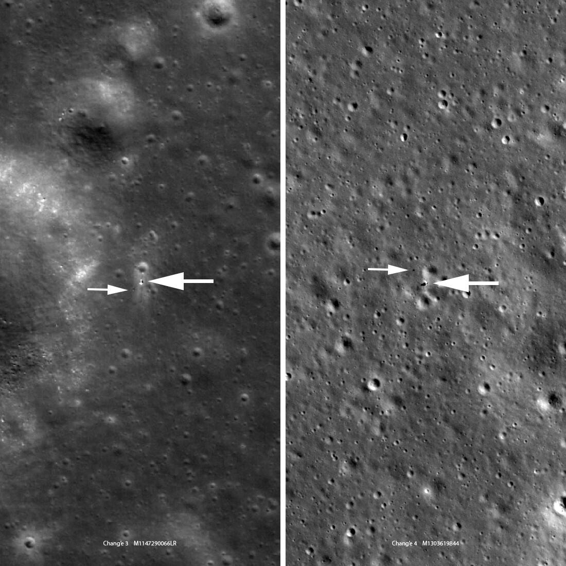 NASA/Goddard/Arizona State University. Public domain (NASA / US government work).
The problem
Section titled “The problem”Yutu-2 had to drive a six-wheel rover across a cratered far-side floor with no line of sight to Earth, through lunar nights and local noon, planning each drive on the ground from the rover’s own imagery. Three constraints bound the site: thermal control wanted latitudes near 45 degrees S, the relay link required longitudes between 161 deg E and 161 deg W, and the landing area needed an average slope below 8 degrees over a flat region larger than 50 by 30 km [5]. Every command and telemetry frame passes through a relay satellite, so the ground confirms a command only 3 to 4 minutes after it is sent [6], [11]. The soil was unknown: no far-side surface strength had been measured before landing, and the descent trajectory itself had to be reconstructed from images because no radio tracking existed between the lander and the relay [4].
What has flown
Section titled “What has flown”Yutu-2 (Chang’e 4, landed 3 January 2019). The rover is the first to operate on the lunar far side, in Von Kármán crater within the South Pole-Aitken basin [5], [13]. Landing was at 177.5884 deg E, 45.4565 deg S, and the first twelve lunar days produced more than 300 m of travel over 73 waypoints [6]. The descent camera returned about 5300 images from kilometer altitude to touchdown, and the landing site was positioned photogrammetrically from 180 of them, a result that differs from the LRO-derived coordinate by 415 m because of the terrain reference rather than the method [4], [14]. The rover is a 6-wheel rocker-bogie vehicle with an internal differential, all wheels driven and the front and rear pairs steered, wheels of aluminum alloy hub and mesh with 24 grousers in two staggered rows, 20 degree gradeability and 200 mm obstacle height, and seven working modes [2].
Operations. After a ground command the rover responds in about 10 s, the first telemetry frame arrives 80 to 100 s later and refreshes every 24 s [6]. Each command therefore carries a time parameter: mechanism motion is allotted theoretical time plus 6 s and the next imaging command follows at theoretical time plus 8 s [6]. Onboard autonomy covers local planning, emergency obstacle avoidance and emergency protection; route selection stays on the ground, and the operators describe teleoperation as the most important control method [6], [10]. Drive segments are 4 to 7 m, and the rover hibernates through the night and local noon [10]. Pancam (2352 by 1728 pixels, 22.9 by 16.9 degrees) and Navcam (1024 by 1024, 46.6 degrees, 270 mm stereo base) share a mast bar, with a body-mounted Hazcam [14]. At each waypoint Navcam and Hazcam imagery produces a local elevation model at 0.02 m resolution that feeds obstacle recognition [10]. Hazcam stereo resolved a pit about 45 cm across and 6 cm deep with a stone inside that Navcam had missed [10].
Localization. Onboard dead reckoning and ground visual positioning run in parallel; they agree at the centimeter to decimeter level over up to 10 m between waypoints, and when the rover slipped badly they differed by more than 1 m and the visual solution corrected the odometry [10]. The cross-site method developed for the Chang’e-3 Yutu uses ASIFT tie points in search regions predicted from dead reckoning; against indoor GPS truth in a simulated lunar field it gave 1 to 4 percent of traverse length error against 15 percent for dead reckoning [9].
Occlusion and sleep planning. A skyline is extracted from a monocular Navcam or Pancam image, and the Sun or the relay is declared occluded when its altitude falls below the skyline in its direction; the result sets the timing of sleep and reboot commands [6]. Six skyline images had been made by the end of twelve lunar days, with skyline altitudes all below 3 degrees, and only about 2.5 percent of the landing area is relatively flat plain between hazardous craters [6]. Path planning is a cost-map search that includes illumination, communication geometry and shadow as cost terms [10].
Relay. Queqiao, in a halo orbit about the Earth-Moon L2 point, carries a 4.2 m antenna; forward commands run at 125 bit/s and return links deliver 285 kbit/s from the rover and 555 kbit/s from the lander in the link budget [11].
Instruments. The 60 MHz lunar penetrating radar channel reached about 330 m, and the 500 MHz channel about 35 m. Near-surface returns of the 60 MHz channel are saturated by coupling to the rover’s own metal structure, so analysis starts at 52 m [3]. Five continuous reflectors at 51.8, 63.2, 96.2, 130.2 and 225.8 m were interpreted as at least four lava flows over buried ejecta, with a mare basalt loss tangent of 0.0040 to 0.0061, and the earlier Apollo sounder saw only mare-bedrock interfaces at apparent depths of 1 to 1.6 km [3]. The Pancam digital elevation model at 5 cm grid spacing showed the site sits on overlapping ejecta from Finsen and Alder rather than exposed mare basalt [15]. The imaging spectrometer covers 900 to 2395 nm and identified the Longji target rock as low-calcium pyroxene tied to Zhinyu crater ejecta [2].
Long-term status. Odometry is reported intermittently; as of 9 April 2024 the comparison table of a survey lists Zhurong at 1921 m over 347 sols and gives no Yutu-2 row, so the 1.6 km total in the record carries no date [1].
Other far-side and lunar precedents. Chang’e 6 selected a landing zone in the southern Apollo basin at 150 to 158 W and 41 to 45 S [24]. It returned 1935.3 g of far-side soil [23], using an autonomous binocular vision pipeline to choose scoop points and a 6D pose estimate of the sampler, with about 30 mm and 2 degrees of uncontrolled arm error that the pipeline compensates, quantified on Earth testbeds [22]. Chang’e 5 recovered about 1 m of drill core against a 2 m goal and scooped in 12 scoops [31]. The Japanese LEV-1 hopper, landed with SLIM on 20 January 2024, made six hops on the surface and transmitted directly to Earth for 1 hour 51 minutes [25].
What is being tried now
Section titled “What is being tried now”Terramechanics from flight data (flown data, ground inference). A digital twin coupling multibody dynamics with a grouser-wheel model was fitted to the lunar day 41 traverse to the Longji rock [2]. Wheels worked in skid with slip ratio 0 to -0.075 and never below -0.1, and the inverted parameters are an internal friction angle of 21.5 to 42.0 degrees, cohesion 520 to 3154 Pa, an external friction angle of 8.3 to 16.5 degrees and a bearing capacity near 4 kPa at about 8 mm sinkage [2]. A separate slip-sinkage analysis from panoramic-camera wheel tracks reached a soil strength above the Chang’e-3 value and close to Apollo 15 [8]. For the nearside reference, a nonlinear Winkler model joins 776 Apollo bootprints (920 Pa/mm) with about 1000 Lunokhod penetrometer measurements (2,300 Pa/mm) [30]. Returned Chang’e-6 soil has a static angle of repose of 52.9 degrees and a dynamic angle of 70.4 degrees, above all Apollo and Chang’e-5 simulants, consistent with a cohesive far side [16].
Simulation of Yutu-class mobility (ground simulation). An SPH continuum model of granular terrain run in the Chrono multibody simulator reproduces DEM single-wheel force curves at lower cost and was applied to a six-wheel Yutu rover model at 137 kg under lunar gravity [12]. A 30 ms analytical mission evaluator for sub-50 kg rovers finds rigid four-wheel layouts dominate under smooth-regolith objectives, with a six-wheel rocker-bogie chassis such as Yutu-2’s entering the optimal set only once an obstacle requirement is imposed [7]. Neither has been compared with Yutu-2 flight telemetry.
Wheel design (ground test, one flown). Single-wheel tests of a 200 mm grouser wheel found different traction in Toyoura sand and FJS-1 simulant [29]. A variable grouser-height wheel (0 to 17.5 mm, 16 grousers) was evaluated over 750 gantry trials [28]. The octagonal grouser of LEV-1, derived with resistive force theory and tested in silica sand, was confirmed by operation after the SLIM landing [26]. Transfer learning to classify wheel slip for a new rover from a fleet of prior lunar rovers is a proposal [27].
Crater-based absolute localization (simulation and field test, not flown). The detection front end gave 3-sigma crater-center errors of 0.28 m for 5 m craters up to 1.94 m for 20 m craters with lidar, and 1.02 to 4.48 m with stereo, on simulated imagery [17]. The LunarNav particle filter converged to about 0.75 to 2 m in simulated traverses, raised the work from TRL 2 to TRL 4, and its stereo detector did not generalize to real Chang’e 4 rover imagery [18]. ShadowNav extends the approach to night with a lamp, reaching 1.7 to 3.8 m in Blender simulations [19].
Teleoperation under delay (simulator studies). Operator speed driving an Artemis Lunar Terrain Vehicle fell from 3.24 km/h at no delay to 1.76 km/h at 8 s round trip [20]. A virtual-reality plan-then-execute interface was compared with keyboard and mouse with nine operators and no communication delay, in a satellite-servicing task [21]. Neither involved a lunar rover.
The numbers
Section titled “The numbers”| Quantity | Value | Source |
|---|---|---|
| Landing | 3 January 2019, 177.5884 deg E, 45.4565 deg S | [6], [5] |
| First twelve lunar days | more than 300 m, 73 waypoints | [6] |
| Wheels, grousers | 6 driven, 24 grousers | [2] |
| Gradeability, obstacle height | 20 degrees, 200 mm | [2] |
| Command confirmation | 3 to 4 minutes | [6] |
| Local DEM resolution | 0.02 m | [10] |
| Dead reckoning vs visual positioning | cm to dm over 10 m; over 1 m when slipping | [10] |
| Internal friction angle | 21.5 to 42.0 degrees | [2] |
| Cohesion | 520 to 3154 Pa | [2] |
| External friction angle | 8.3 to 16.5 degrees | [2] |
| Bearing capacity | about 4 kPa at 8 mm sinkage | [2] |
| LPR 60 MHz penetration | about 330 m | [3] |
| LPR 500 MHz penetration | about 35 m | [3] |
| Mare basalt loss tangent | 0.0040 to 0.0061 | [3] |
| Forward link, relay | 125 bit/s | [11] |
| Return link from rover, relay | 285 kbit/s | [11] |
What is not established
Section titled “What is not established”Power generation, battery capacity, processor, thermal limits and rover data rates are not published in the open literature retrieved here. The regolith parameters are model inversions with wide bounds, anchored to Apollo values, from one traverse on one lunar day; Yutu-2 has no drawbar pull, torque or shear sensor, and the two independent site estimates differ in method [2], [8]. Ground localization accuracy is reported without a distribution or independent truth [10]. Wheel design, crater-based localization and teleoperation delay studies are ground tests or simulations, and none has been checked against Yutu-2 flight data [12], [18], [20]. The odometry total carries no published date [1].
References
- Chien, S. A., Visentin, G. and Basich, C. (2024). Exploring Beyond Earth using Space Robotics: Update
. Science Robotics. Source
BibTeX
@article{chien2024exploring, title = {Exploring Beyond Earth using Space Robotics: Update}, author = {Chien, Steve A. and Visentin, Gianfranco and Basich, Connor}, journal = {Science Robotics}, publisher = {JPL Open Repository}, year = {2024}, doi = {10.48577/jpl.2ezlhn}, abstract = {Robotic spacecraft enable exploration of our solar system, beyond our human presence. While spacecraft have explored every planet in the solar system, the frontiers of space robotics are at the cutting edge of landers, rovers, and now atmospheric explorers where robotic spacecraft must interact intimately with their environment to explore beyond the reach of flyby and orbital remote sensing.In 2017, we surveyed space robotics - telling the rich history of robotic explorers to the Moon, Mars, and beyond. In this article, we describe the tremendous growth in space robotics missions in the period 2017-2024 with many new entities participating in missions to the surface of the Moon, Mars, and beyond. We also describe the recent development of aerial missions to planets and moons as exemplified by the Ingenuity helicopter on Mars, the Dragonfly mission to Titan, and the planned Sample Recovery Helicopter to Mars. As with the 2017 survey, we seek to provide a big picture of developments and directions in space robotics. Additionally, we focus on sub orbital robotics - landers, rovers, and aerial vehicles, with associated challenges in sensing, manipulation, and mobility.} } - Ding, L., Zhou, R., Yu, T., Yang, H., He, X., Gao, H., Wang, J., Yuan, Y. and Wang, J. (2024). Lunar rock investigation and tri-aspect characterization of lunar farside regolith by a digital twin
. Nature Communications. Source
BibTeX
@article{ding2024lunar, title = {Lunar rock investigation and tri-aspect characterization of lunar farside regolith by a digital twin}, author = {Ding, Liang and Zhou, Ruyi and Yu, Tianyi and Yang, Huaiguang and He, Ximing and Gao, Haibo and Wang, Juntao and Yuan, Ye and Wang, Jia}, journal = {Nature Communications}, volume = {15}, pages = {1547}, year = {2024}, doi = {10.1038/s41467-024-46233-8}, abstract = {Abstract Yutu-2 rover conducted an exciting expedition on the 41st lunar day to investigate a fin-shaped rock at Longji site (45.44°S, 177.56°E) by extending its locomotion margin on perilous peaks. The varied locomotion encountered, especially multi-form wheel slippage, during the journey to the target rock, established unique conditions for a fin-grained lunar regolith analysis regarding bearing, shear and lateral properties based on terramechanics. Here, we show a tri-aspect characterization of lunar regolith and infer the rock’s origin using a digital twin. We estimate internal friction angle within 21.5°−42.0° and associated cohesion of 520-3154 Pa in the Chang’E-4 operational site. These findings suggest shear characteristics similar to Apollo 12 mission samples but notably higher cohesion compared to regolith investigated on most nearside lunar missions. We estimate external friction angle in lateral properties to be within 8.3°−16.5°, which fills the gaps of the lateral property estimation of the lunar farside regolith and serves as a foundational parameter for subsequent engineering verifications. Our in-situ spectral investigations of the target rock unveil its composition of iron/magnesium-rich low-calcium pyroxene, linking it to the Zhinyu crater (45.34°S, 176.15°E) ejecta. Our results indicate that the combination of in-situ measurements with robotics technology in planetary exploration reveal the possibility of additional source regions contributing to the local materials at the Chang’E-4 site, implying a more complicated geological history in the vicinity.} } - Li, C., Su, Y., Pettinelli, E., Xing, S., Ding, C., Liu, J., Ren, X., Lauro, S. E. and Soldovieri, F. (2020). First look by the Yutu-2 rover at the deep subsurface structure at the lunar farside
. Nature Communications. Source
BibTeX
@article{li2020first, title = {First look by the Yutu-2 rover at the deep subsurface structure at the lunar farside}, author = {Li, Chunlai and Su, Yan and Pettinelli, Elena and Xing, Shuguo and Ding, Chunyu and Liu, Jianjun and Ren, Xin and Lauro, Sebastian Emanuel and Soldovieri, Francesco}, journal = {Nature Communications}, volume = {11}, pages = {3426}, year = {2020}, doi = {10.1038/s41467-020-17262-w}, abstract = {Abstract The unequal distribution of volcanic products between the Earth-facing lunar side and the farside is the result of a complex thermal history. To help unravel the dichotomy, for the first time a lunar landing mission (Chang’e-4, CE-4) has targeted the Moon’s farside landing on the floor of Von Kármán crater (VK) inside the South Pole-Aitken (SPA). We present the first deep subsurface stratigraphic structure based on data collected by the ground-penetrating radar (GPR) onboard the Yutu-2 rover during the initial nine months exploration phase. The radargram reveals several strata interfaces beneath the surveying path: buried ejecta is overlaid by at least four layers of distinct lava flows that probably occurred during the Imbrium Epoch, with thicknesses ranging from 12 m up to about 100 m, providing direct evidence of multiple lava-infilling events that occurred within the VK crater. The average loss tangent of mare basalts is estimated at 0.0040-0.0061.} } - Liu, J., Ren, X., Yan, W., Li, C., Zhang, H., Jia, Y., Zeng, X., Chen, W., Gao, X., Liu, D., Tan, X., Zhang, X., Ni, T., Zhang, H., Zuo, W., Su, Y. and Wen, W. (2019). Descent trajectory reconstruction and landing site positioning of Chang'E-4 on the lunar farside
. Nature Communications. Source
BibTeX
@article{liu2019descent, title = {Descent trajectory reconstruction and landing site positioning of Chang'E-4 on the lunar farside}, author = {Liu, Jianjun and Ren, Xin and Yan, Wei and Li, Chunlai and Zhang, He and Jia, Yang and Zeng, Xingguo and Chen, Wangli and Gao, Xingye and Liu, Dawei and Tan, Xu and Zhang, Xiaoxia and Ni, Tao and Zhang, Hongbo and Zuo, Wei and Su, Yan and Wen, Weibin}, journal = {Nature Communications}, volume = {10}, year = {2019}, doi = {10.1038/s41467-019-12278-3}, abstract = {Abstract Chang’E-4 (CE-4) was the first mission to accomplish the goal of a successful soft landing on the lunar farside. The landing trajectory and the location of the landing site can be effectively reconstructed and determined using series of images obtained during descent when there were no Earth-based radio tracking and the telemetry data. Here we reconstructed the powered descent trajectory of CE-4 using photogrammetrically processed images of the CE-4 landing camera, navigation camera, and terrain data of Chang’E-2. We confirmed that the precise location of the landing site is 177.5991°E, 45.4446°S with an elevation of −5935 m. The landing location was accurately identified with lunar imagery and terrain data with spatial resolutions of 7 m/p, 5 m/p, 1 m/p, 10 cm/p and 5 cm/p. These results will provide geodetic data for the study of lunar control points, high-precision lunar mapping, and subsequent lunar exploration, such as by the Yutu-2 rover.} } - Liu, J., Zeng, X., Li, C., Ren, X., Yan, W., Tan, X., Zhang, X., Chen, W., Zuo, W., Liu, Y., Liu, B., Liu, D., Zhou, Q. and Ouyang, Z. (2021). Landing Site Selection and Overview of China's Lunar Landing Missions
. Space Science Reviews. Source
BibTeX
@article{liu2021landing, title = {Landing Site Selection and Overview of China's Lunar Landing Missions}, author = {Liu, Jianjun and Zeng, Xingguo and Li, Chunlai and Ren, Xin and Yan, Wei and Tan, Xu and Zhang, Xiaoxia and Chen, Wangli and Zuo, Wei and Liu, Yuxuan and Liu, Bin and Liu, Dawei and Zhou, Qin and Ouyang, Ziyuan}, journal = {Space Science Reviews}, volume = {217}, pages = {6}, year = {2021}, doi = {10.1007/s11214-020-00781-9}, abstract = {Abstract Landing site selection is of fundamental importance for lunar landing mission and it is closely related to the scientific goals of the mission. According to the widely concerned lunar science goals and the landing site selection of the ongoing lunar missions; China has carried out the selection of landing site for a series of Chang’ E (CE) missions. Under this background, this paper firstly introduced the principles, process, method and result of landing site selection of China’s Lunar Exploration Program (CLEP), and then analyzed the support of the selected landing sites to the corresponding lunar research. This study also pointed out the outcomes that could possibly contribute to the key lunar questions on the basis of the selected landing sites of CE-4 and CE-5 such as deep material in South Pole-Aitken (SPA) basin, lunar chronology, volcanic thermodynamics and geological structure evolution history of the Moon. Finally, this approach analyzed the development trend of China’s follow-up lunar landing missions, and suggested that the South Pole Region of the Moon could be the landing site of high priority for the future CE missions.} } - Peng, S., Shen, Z., Jia, Y., Wen, B., Dang, Z., Li, H. and Li, Y. (2019). Integrated Ground and On-Board Safe Operation Design for the Chang'e-4 Rover
. Scientia Sinica Technologica, 12. Source
BibTeX
@article{peng2019onboard, title = {Integrated Ground and On-Board Safe Operation Design for the {Chang'e-4} Rover}, author = {Peng, Song and Shen, Zhenrong and Jia, Yang and Wen, Bo and Dang, Zhaolong and Li, Haifei and Li, Ying}, journal = {Scientia Sinica Technologica}, volume = {49}, number = {12}, pages = {1408--1417}, year = {2019}, doi = {10.1360/sst-2019-0078}, abstract = {The Chinese Chang’E-4 lunar probe achieved the first landing and detection mission on the lunar far side in human history. The working of the rover faced great challenges owing to mission restrictions such as relay communication by satellite and the complicated lunar far-side terrain. In order to improve the safety and reliability of the rover, the mission characteristics were analyzed, including the control feedback delay, rugged terrain of the lunar far side, occlusion by mountains, and uncertainty of the lunar environment. The safe operation architecture was given based on two aspects: self-control onboard and intelligent control on the ground. Onboard-ground designs were prepared to solve key problems, such as the safe control of mechanisms, reliable separation of the rover and lander, safe movement on the lunar surface, autonomous thermal control, sleeping and rebooting, and safe and efficient work. These measures ensured that the Chang’E-4 rover could successfully move and detect on the lunar far side.} } - Reifschneider, J. (2026). RoverDevKit: An open, physics-grounded tradespace toolkit for conceptual design of lunar micro-rovers
. arXiv preprint. Source
BibTeX
@article{reifschneider2026roverdevkit, title = {RoverDevKit: An open, physics-grounded tradespace toolkit for conceptual design of lunar micro-rovers}, author = {Reifschneider, Jon}, journal = {arXiv preprint}, year = {2026}, doi = {10.48550/arxiv.2606.21755}, abstract = {Lunar micro-rovers under 50 kg are a rapidly growing vehicle class, yet open, benchmarked tools for running optimization across design trades remain scarce. Rover sizing is a highly coupled problem with a feedback loop specific to surface vehicles: a heavier rover sinks deeper into loose regolith, deeper sinkage costs more power, more power requires a larger array, and the array adds mass. We present RoverDevKit, a tradespace exploration toolkit with an open evaluator that couples a closed-form wheel-soil model with bottom-up mass, solar-power, thermal-survival, and traverse models. It is fast enough to serve as the fitness function of a multi-objective genetic algorithm (NSGA-II): one search of 3000 mission evaluations takes under a minute on a single laptop core. We use it to map the trades among distance traveled, vehicle mass, and slope capability on mare, polar, highland, and crater-rim missions. Across those missions the limiting factor changes: energy storage at high latitude, slope traction on loose highland regolith, and traverse range on mare and crater-rim terrain. The wheel-soil model matches measured single-wheel drawbar pull on two independent datasets to within the 20-30% error typically reported for this class of model, and the mass model predicts published 5-50 kg rover masses to 10.5% median absolute error. A check against five published in-class designs places them near the designs the optimizer selects. Re-running the search after applying that wheel-soil comparison error leaves these conclusions unchanged.} } - Tang, Z., Liu, J., Wang, X., Ren, X., Chen, W., Yan, W., Zhang, X., Tan, X., Zeng, X., Liu, D., Zhang, H., Wen, W., Zuo, W., Su, Y., Yang, J. and Li, C. (2020). Physical and Mechanical Characteristics of Lunar Soil at the Chang'E-4 Landing Site
. Geophysical Research Letters. Source
BibTeX
@article{tang2020physical, title = {Physical and Mechanical Characteristics of Lunar Soil at the Chang'E-4 Landing Site}, author = {Tang, Zhencheng and Liu, Jianjun and Wang, Xing and Ren, Xin and Chen, Wangli and Yan, Wei and Zhang, Xiaoxia and Tan, Xu and Zeng, Xingguo and Liu, Dawei and Zhang, Hongbo and Wen, Weibin and Zuo, Wei and Su, Yan and Yang, Jianfeng and Li, Chunlai}, journal = {Geophysical Research Letters}, volume = {47}, year = {2020}, doi = {10.1029/2020gl089499}, abstract = {Abstract Chang'E‐4, with the Yutu‐2 rover, is the first lunar probe to successfully land and conduct a tour on the far side of the Moon from early 2019. We analyze the physical and mechanical characteristics of lunar soil through the in situ terrain data collected by the panoramic camera onboard the Yutu‐2 rover. With the slip ratio and wheel sinkage obtained by the derived Digital Orthophoto Map (DOM) and Digital Elevation Model (DEM), the mechanical parameters of lunar soil are derived from the slip‐sinkage model. These mechanical parameters and wheel size of the rover are used to obtain the pressure‐sinkage curves, which can estimate the lunar soil strength. The experimental results indicate that the soil strength at the Chang'E‐4 landing site is much higher than that at the Chang'E‐3 landing site. The discrepancies in lunar soil strength between the two landing sites may be related to the local surface topography and degree of space weathering.} } - Wan, W., Liu, Z., Di, K., Wang, B. and Zhou, J. (2014). A Cross-Site Visual Localization Method for Yutu Rover
. IEEE Transactions on Aerospace and Electronic Systems. Source
BibTeX
@article{wan2014cross, title = {A Cross-Site Visual Localization Method for Yutu Rover}, author = {Wan, Wenhui and Liu, Z. and Di, Kaichang and Wang, B. and Zhou, Jianliang}, journal = {IEEE Transactions on Aerospace and Electronic Systems}, volume = {XL-4}, pages = {279-284}, publisher = {Copernicus GmbH}, year = {2014}, doi = {10.5194/isprsarchives-xl-4-279-2014}, abstract = {Abstract. Localization of the rover is critical to support science and engineering operations in planetary rover missions, such as rover traverse planning and hazard avoidance. It is desirable for planetary rover to have visual localization capability with high degree of automation and quick turnaround time. In this research, we developed a visual localization method for lunar rover, which is capable of deriving accurate localization results from cross-site stereo images. Tie points are searched in correspondent areas predicted by initial localization results and determined by ASIFT matching algorithm. Accurate localization results are derived from bundle adjustment based on an image network constructed by the tie points. In order to investigate the performance of proposed method, theoretical accuracy analysis on is implemented by means of error propagation principles. Field experiments were conducted to verify the effectiveness of the proposed method in practical applications. Experiment results prove that the proposed method provides more accurate localization results (1 %~4 %) than dead-reckoning. After more validations and enhancements, the developed rover localization method has been successfully used in Chang'e-3 mission operations.} } - Wang, J., Li, J., Wang, S., Yu, T., Rong, Z., He, X., You, Y., Zou, Q., Wan, W., Wang, Y., Gou, S., Liu, B., Peng, M., Di, K., Liu, Z., Jia, M., Xin, X., Chen, Y., Cheng, X., Feng, X., Liu, C., Han, S. and Liu, X. (2020). Computer Vision in the Teleoperation of the Yutu-2 Rover
. ISPRS Annals of the Photogrammetry, Remote Sensing and Spatial Information Sciences. Source
BibTeX
@article{wang2020computer, title = {Computer Vision in the Teleoperation of the Yutu-2 Rover}, author = {Wang, J. and Li, Jinhua and Wang, S. and Yu, Tianyi and Rong, Z. and He, Ximing and You, Y. and Zou, Q. and Wan, Wenhui and Wang, Y. and Gou, Sheng and Liu, B. and Peng, Man and Di, Kaichang and Liu, Z. and Jia, M. and Xin, X. and Chen, Yuan and Cheng, X. and Feng, X. and Liu, Chuankai and Han, Shaojin and Liu, Xiyao}, journal = {ISPRS Annals of the Photogrammetry, Remote Sensing and Spatial Information Sciences}, volume = {V-3-2020}, pages = {595--602}, year = {2020}, doi = {10.5194/isprs-annals-v-3-2020-595-2020}, abstract = {Abstract. On January 3, 2019, the Chang'e-4 (CE-4) probe successfully landed in the Von Kármán crater inside the South Pole-Aitken (SPA) basin. With the support of a relay communication satellite "Queqiao" launched in 2018 and located at the Earth-Moon L2 liberation point, the lander and the Yutu-2 rover carried out in-situ exploration and patrol surveys, respectively, and were able to make a series of important scientific discoveries. Owing to the complexity and unpredictability of the lunar surface, teleoperation has become the most important control method for the operation of the rover. Computer vision is an important technology to support the teleoperation of the rover. During the powered descent stage and lunar surface exploration, teleoperation based on computer vision can effectively overcome many technical challenges, such as fast positioning of the landing point, high-resolution seamless mapping of the landing site, localization of the rover in the complex environment on the lunar surface, terrain reconstruction, and path planning. All these processes helped achieve the first soft landing, roving, and in-situ exploration on the lunar farside. This paper presents a high-precision positioning technology and positioning results of the landing point based on multi-source data, including orbital images and CE-4 descent images. The method and its results have been successfully applied in an actual engineering mission for the first time in China, providing important support for the topographical analysis of the landing site and mission planning for subsequent teleoperations. After landing, a 0.03 m resolution DOM was generated using the descent images and was used as one of the base maps for the overall rover path planning. Before each movement, the Yutu-2 rover controlled its hazard avoidance cameras (Hazcam), navigation cameras (Navcam), and panoramic cameras (Pancam) to capture stereo images of the lunar surface at different angles. Local digital elevation models (DEMs) with a 0.02 m resolution were routinely produced at each waypoint using the Navcam and Hazcam images. These DEMs were then used to design an obstacle recognition method and establish a model for calculating the slope, aspect, roughness, and visibility. Finally, in combination with the Yutu-2 rover mobility characteristics, a comprehensive cost map for path search was generated.By the end of the first 12 lunar days, the Yutu-2 rover has been working on the lunar farside for more than 300 days, greatly exceeding the projected service life. The rover was able to overcome the complex terrain on the lunar farside, and travelled a total distance of more than 300 m, achieving the "double three hundred" breakthrough. In future manned lunar landing and exploration of Mars by China, computer vision will play an integral role to support science target selection and scientific investigations, and will become an extremely important core technology for various engineering tasks.} } - Wu, W., Wang, Q., Tang, Y., Yu, D., Wang, C., Liu, J., Zheng, L., Zhang, L. and Wang, F. (2021). Development and Prospect of Chinese Lunar Relay Communication Satellite
. Space: Science & Technology. Source
BibTeX
@article{wu2021development, title = {Development and Prospect of Chinese Lunar Relay Communication Satellite}, author = {Wu, Weiren and Wang, Qiong and Tang, Yuhua and Yu, Dengyun and Wang, Chi and Liu, Jizhong and Zheng, Lei and Zhang, Lihua and Wang, Feng}, journal = {Space: Science & Technology}, volume = {2021}, pages = {3471608}, year = {2021}, doi = {10.34133/2021/3471608}, abstract = {Relay communication satellites play a very important role on the lunar far side and pole areas exploration missions. Queqiao relay communication satellite was developed to provide relay communication support for the lander and the rover of Chang’e-4 mission landing on the far side of the Moon. From entering into the halo mission orbit around Earth-Moon libration point 2 on June 14, 2018, it has operated on the orbit more than thirty months. It worked very well and provided reliable, continuous relay communication support for the lander and the rover to accomplish the goals of Chang’e-4 lunar far side soft landing and patrol exploration mission. Exploration of the lunar south polar regions is of high scientific interest. A new relay communication satellite for Chinese south pole exploration mission is also under study. The system design and on-orbit operation status of Queqiao relay communication satellite were summarized in this paper. The system concept of the relay communication satellite for lunar south pole exploration missions is proposed. Finally, the future development and prospect of the lunar relay communication satellite system are given.} } - Zhou, L., Zhang, Y., Shi, J., Hu, W. and Negrut, D. (2025). An analysis of the Yutu lunar rover's mobility performance using a multibody dynamics framework and a physics-based terramechanics model
. Research Square preprint. Source
BibTeX
@article{zhou2025analysis, title = {An analysis of the Yutu lunar rover's mobility performance using a multibody dynamics framework and a physics-based terramechanics model}, author = {Zhou, Lebin and Zhang, Yuemin and Shi, Junwei and Hu, Wei and Negrut, Dan}, journal = {Research Square preprint}, year = {2025}, doi = {10.21203/rs.3.rs-6489552/v1}, abstract = {Abstract The interaction between wheels and soil has a significant impact on the dynamics of extraterrestrial vehicles in terrame-chanics applications. With very few exceptions, the mobility analysis of extraterrestrial rovers has been carried out using empirical terramechanics models originally established for military vehicle mobility analysis. This contribution employs a physics-based terramechanics model, the so called continuum representation model (CRM), which employs partial differential equations solved using the smoothed particle hydrodynamics (SPH) method. The resulting terramechanics model displays the speed of the simpler empirical models, yet produces results comparable in fidelity to those generated by the computationally costly discrete element method (DEM). We demonstrate the versatility of the CRM approach by simulating the single-wheel system of the Yutu lunar rover. Simulations were conducted to comparatively analyze the effects of particle size, slip control policy, and soil parameters on wheel performance. The accuracy of the single-wheel CRM results was assessed using “ground truth” DEM results. Subsequently, to gain a system-level understanding of the performance of the Yutu rover, the vehicle was modeled as a multibody system, and mobility simulations were run on de-formable CRM terrain. The performance of the full rover, as captured in tractive force, wheel torque, wheel sinkage, and traction vs. slope tests, was examined under various test conditions. Finally, we examine how various wheel features, e.g., its radius and grouser width/height/count, affect the mobility performance of the rover. All simulations were conducted using an open-source, publicly available simulator called Chrono. The scripts and models used to generate the results presented in this paper are available upon request to support reproducibility studies and further research.} } - (2026). NASA NSSDCA: Chang'e 4. nssdc.gsfc.nasa.gov/nmc/spacecraft/display.action
BibTeX
@misc{nasanssdcachange,
  title = {NASA NSSDCA: Chang'e 4},
  organization = {nssdc.gsfc.nasa.gov},
  year = {2026},
  url = {https://nssdc.gsfc.nasa.gov/nmc/spacecraft/display.action?id=2018-103A}
}