Opportunity
Program pages NASA: Mars Exploration Rovers
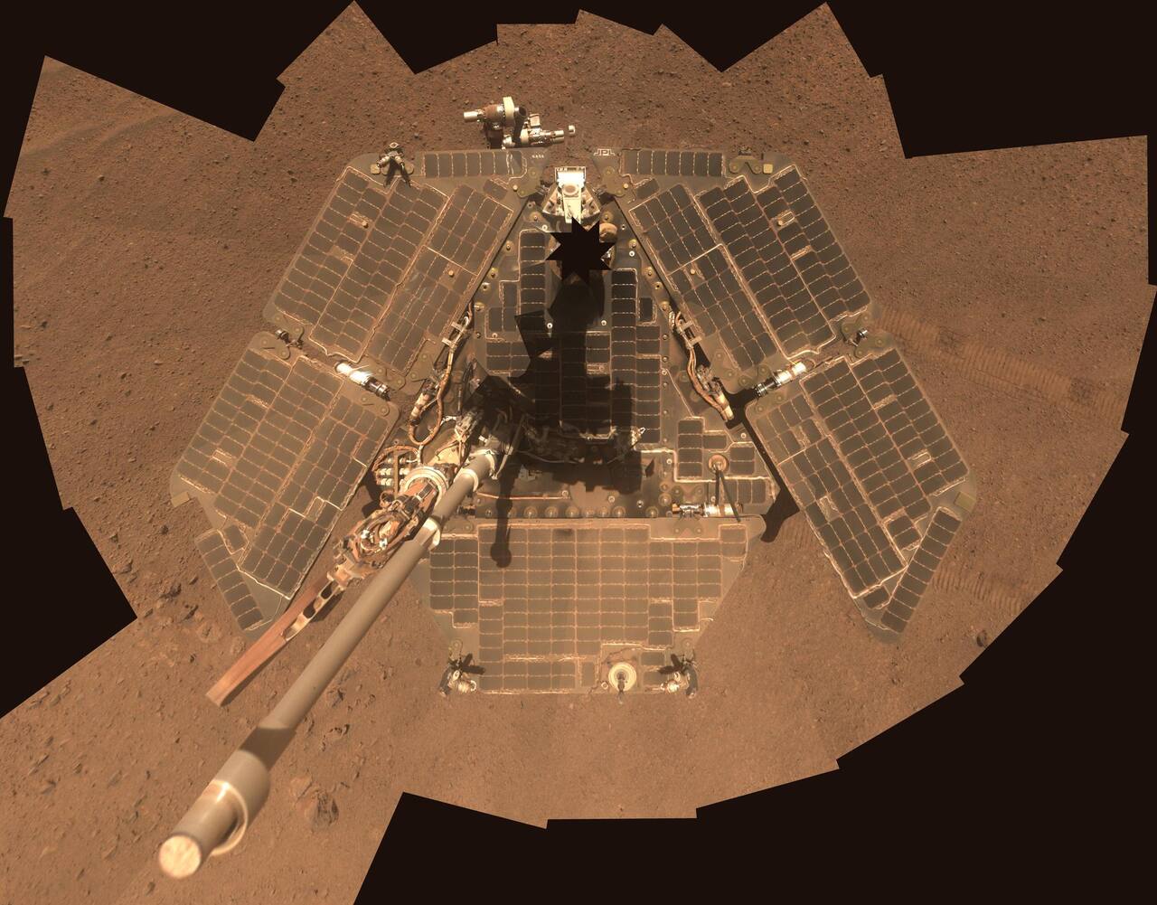 NASA/JPL-Caltech/Cornell Univ./Arizona State Univ. Public domain (NASA / US government work).
The problem
Section titled “The problem”A solar-powered, teleoperated vehicle had to cross Meridiani Planum on a 20 MHz processor [2] without a map of what lay ahead, and keep working through dust, cold and component wear for far longer than the 90 sols it was planned for [1]. Four environmental effects set the requirements.
Meridiani is flat and less rocky than Gusev, which allows long drives, but wind-formed ripples of loose sand are geometrically unremarkable and so invisible to a hazard detector that reasons about shape [11]. Aeolian sand has a cohesion at or below 1 kPa and a friction angle near 30 degrees, against 4 to 25 kPa for cemented material, so the bearing capacity differs by an order of magnitude with no difference in relief [9]. Two dust processes degrade the arrays: suspended dust reduces intensity with optical depth, and deposited dust obscures the cells cumulatively [4]. The temperature swing across a sol commonly exceeds 80 K at low latitude [7]. Data return depends on orbiter relay passes of a few minutes each [24].
What has flown
Section titled “What has flown”Opportunity, 2004 to 2018. It landed in Meridiani Planum on 25 January 2004 UTC [1], [16]. Its twin Spirit landed in Gusev crater and operated until 2010; through March 2005 the two had driven 3158 m and 4161 m respectively [2]. The NASA mission page dates the landing to 24 January, which is the Pacific date; dates here are UTC [16]. The end-of-mission report gives Opportunity alone 217,594 images, 41.96 GB over 5830 communication passes, and 45,161.04 m over 1403 driving sols, with last contact on sol 5111 (10 June 2018) [17]. The off-Earth wheeled odometry record is 45.16 km over 14.375 years [10]. Landing site candidates had been compared in 2002 by landing ellipse dimensions, and a revised navigation estimate led to no change in the Meridiani ellipse [32].
Purgatory ripple, sols 446 to 484. On sol 446 the rover executed 50 m of blind driving into what imagery showed as an unremarkable pile of sand; the wheels turned through 50 m while the vehicle advanced about 2 m [2]. Extraction took 39 sols [11]. Commanded 2 m motions with the wheels steered for a 23 degree heading change produced progress on the order of 1 mm on many sols [2]. Driving ended on sol 484 when visual odometry failed to converge three times, because the tracked features had left the field of view [2]. Through sol 2300 (13 July 2010) the rover had driven 21,760 m by wheel-turn odometry, 16,389 m of it after leaving the ripple at sol 511 [11].
Visual odometry and slip checks. MER flew visual odometry on another world for the first time. After each commanded 2 m of driving, it estimated actual motion; if little or none was confirmed more commands were sent, and once it measured non-trivial motion or failed to converge all driving stopped [2]. Blind segments over sand were then capped, initially at 5 m, followed by a 20 cm slip check measured by visual odometry, and checks halted drives before they dug in on sols 501 and 603, so driving resumed the next sol instead of costing 39 [2]. Curiosity later used visual odometry on 87 percent of its drives [27]. Convergence was 95 percent (828 of 875 pairs) on Opportunity and 97 percent (590 of 609) on Spirit, and visual odometry took up to three minutes per step on the RAD6000, so it was commanded selectively: for drives under about 15 m on slopes steeper than 10 degrees, with a dragged wheel, or in sand [2].
Hardware wear. The highest-use wheel drive motor accumulated 92.7 million revolutions against a 10 million cycle qualification, and the left front steering actuator stalled with that wheel toed out 33.3 deg [17]. The right front steering actuator failed on sol 433, leaving the wheel turned inward about 8 degrees, and the instrument deployment device shoulder joint was declared failed on sol 1542, after which the arm was carried in a forward “fishing stow” [11]. Rising right front wheel current, possibly from uneven lubricant, was handled by rotating the wheel back and forth, resting it, and driving mostly backward [11]. A catalog by the operations team records the workaround for each degradation: the Moessbauer cobalt-57 source decayed on a 271 day half-life, raising integration time from 8 hours at landing to 48 hours by 2007, and dust from the 2007 storm obscured all of Opportunity’s Mini-TES signal [19]. Flash sector degradation produced boot failures and data loss, handled by reformatting around bad sectors, until Opportunity ran without usable non-volatile storage [19].
Power and the 2018 storm. The 1.33 m2 array at Meridiani cleaned and dirtied in a seasonally repeatable pattern over eight Mars years and never fell below a dust factor of about 0.43, against about 0.25 at Gusev [18]. Wind gusts repeatedly cleared the arrays; that was not credited in the power budget and accounts for much of the mission duration. The 2018 planet-encircling event reached a peak measured optical depth of 10.8 to 11.1 in eight sols, against 4.72 in twenty-one sols in 2007, and began at Ls 182, the earliest in a decade [20]. Array energy fell from 667 Wh at an optical depth of 0.605 to 22 Wh at 10.8, with battery state of charge at 31 percent against a 40 percent flight rule [18]. The flight team names the absence of an undervoltage lockout between the batteries and the mission clock FPGA as the most likely cause of the loss, since a parasitic load kept draining the cells [20]. More than 1000 recovery commands were radiated before the search ended on 12 February 2019 [17].
The 2007 storm. The June to July 2007 planet-encircling dust storm forced the sequencing team to change planning and power-fault strategies so both rovers survived it; those strategies were then reused in Spirit’s third winter [35].
Science traverse. The Block Island iron-nickel meteorite, about 65 cm wide, was found at sol 1961 [11]. The traverse to Endeavour crater began with the rover about 11 km from the rim at sol 2239; the clay-mineral and hydrated-sulfate identifications on the rim at that date were orbital spectral inferences, not rover measurements [11]. Both rovers together returned more than 300,000 raw images [16]. Surface and orbital observations of fresh craters at Meridiani bracket the latest phase of granule ripple migration at about 50 to 200 ka [34]. Onboard target selection (AEGIS) was uploaded to Opportunity in December 2009 and had sixteen tabulated Mars runs through sol 2550, picking rock targets in navigation camera images and pointing the Pancam at the top-ranked one [33].
What is being tried now
Section titled “What is being tried now”Slip estimation and compensation. A survey of wheel slippage methods covers proprioceptive, exteroceptive and model-based estimation, and torque-based and velocity-based compensation, using the Lunar Roving Vehicle, Lunokhod, Sojourner, MER and MSL slip incidents as motivation [26]. The MER method, visual odometry with a slip check, is a fault-protection threshold on slip ratio, not a soil model; the strength contrast that produces the runaway is not observable from the surface the rover is standing on [5]. Visual odometry remains in service on later rovers: a Curiosity flight change that runs it during motion raised measured average drive rate in the Mars Yard from 51.5 to 77.5 m/hr [27]. Both are flown.
Statistical mobility prediction. This propagates soil parameter uncertainty through a wheel-soil model to bound where the rover ends up, with 2-sigma ellipses of 0.06 by 0.03 m in lunar simulant and 0.16 by 0.01 m in Toyoura sand on a 10 degree side slope; a stochastic response surface took 246 s against 17,526 s for 500-run Monte Carlo [6]. It was tested on a 13.4 kg laboratory testbed and has not run onboard any rover.
Alternatives to Bekker-Janosi terramechanics. Granular resistive force theory and continuum plasticity (material point method) were compared against forced-slip wheel experiments in poppy seeds, sand and Mars Mojave Simulant. Both beat the semi-empirical model on torque and sinkage in poppy seeds, but drawbar pull from all three landed within about 25 percent of measurement, with the traditional model the most accurate [5]. Discrete element simulation of a MER spare flight wheel was fit to single-wheel drawbar and sinkage tests at slip 0 to 0.5 and then used to predict slip of 0.7 to 0.99, where no test data exist [23]. A GPU physics simulator showed that gravity offload by mass reduction gives overoptimistic trafficability, because the soil grains still feel Earth gravity [30]. All of this is ground testing or simulation.
Operations and margin. A catalog of 48 major anomalies on NASA Mars surface missions puts the average loss at 11 percent of prime mission surface duration and 6.6 percent over the full mission [28]. Spirit’s end-of-mission report ties rover life to the product of array dust factor and achievable northerly tilt: production fell from 434 W-h/sol in the first winter to 227 W-h/sol in the third, and the sol 779 wheel failure capped climbable slope near 12 degrees [29].
The numbers
Section titled “The numbers”Specifications
Section titled “Specifications”| Parameter | Value | Source |
|---|---|---|
| Mass | 185 kg | [1] |
| Wheels | six driven, four corner wheels steered, 0.25 m diameter, rocker-bogie | [3] |
| Solar arrays | triple-junction GaInP/GaAs/Ge | [4] |
| Power subsystem | direct energy transfer bus, GaAs triple-junction arrays, Li-ion, Li-SO2 and thermal batteries, 118 pyro events | [31] |
| Rover batteries | Lithion 8 and 10 Ah lithium-ion cells | [25] |
| Processor | RAD6000, 20 MHz | [2] |
| IMU attitude drift | under approximately 3 deg/h | [2] |
| Enclosure | composite honeycomb exoskeleton lined with aerogel | [1] |
| Transponder and SSPA allowable flight temperature | 50 C (protoflight 60 C) | [1] |
| Surface peak daytime temperature | -15 C | [4] |
Mission record
Section titled “Mission record”| Quantity | Value | Source |
|---|---|---|
| Planned mission | 90 sols | [1] |
| Last communication | sol 5111, 10 June 2018 | [17] |
| Total traverse | 45.16 km over 14.375 years | [10] |
| Odometry through sol 2300 | 21,760 m | [11] |
| Images returned | 217,594 | [17] |
| Highest-use drive motor | 92.7 million revolutions against 10 million qualified | [17] |
| Mini-TES | stopped responding sol 2257 | [11] |
| Rock abrasion tool | 38 rocks ground by sol 2300 | [11] |
| Meridiani dust factor minimum | about 0.43 | [18] |
Visual odometry constraints
Section titled “Visual odometry constraints”| Constraint | Value | Source |
|---|---|---|
| Camera field of view / height | 45 deg / 1.5 m | [2] |
| Overlap between stereo pairs | at least 60 percent | [2] |
| Maximum drive per step | 75 cm | [2] |
| Maximum heading change per step | 18 deg | [2] |
| Maximum slip ratio measured | 125 percent | [2] |
| Smallest displacement resolved | 2 mm | [2] |
| Drive rate with visual odometry running continuously | approx 10 m/h | [2] |
Telecommunications
Section titled “Telecommunications”| Link | Value | Source |
|---|---|---|
| X-band LGA | 7.8125 bps uplink / 10 bps downlink minimum | [1] |
| X-band HGA | 2 kbps / 28.8 kbps at shortest range | [1] |
| UHF return | 128 or 256 kbps per pass | [1] |
| Relay passes above 20 deg | approx 1.8 per sol per orbiter, 2 to 8 min | [24] |
| Share of data volume by relay | 89 percent at 90 sols, 97 percent by October 2005 | [24] |
| Mars Global Surveyor relay | dropped for Opportunity after sol 171 | [1] |
Pancam calibration target images (more than 17,000 per rover) were used to derive deposited dust optical depth over the full mission at both sites [21], and the Pancam solar-imaging record gives atmospheric optical depth over 5 Mars years [22].
What is not established
Section titled “What is not established”The slip-check strategy is documented as a flight-validated threshold, but no held source gives the soil strengths at the sol 446 and sol 603 sites, so the mapping from observed slip to bearing capacity is not established [2], [9]. Wheel-soil models are compared only against laboratory data: the plane-strain continuum model and extrapolated response surfaces limit what transfers to a flown 0.25 m wheel [5]. Statistical mobility prediction was validated on three runs per soil on one 10 degree slope [6]. Mission-overview results from the extended traverse rest on opportunistic measurements taken after hardware had degraded [11]. The end-of-mission report is a project self-report, and the loss of contact has no root-cause analysis because the vehicle never responded [17]. The undervoltage lockout cause is the flight team’s most likely explanation, not a confirmed one [20]. Workarounds for Mini-TES, Moessbauer and flash degradation are cataloged from the operators’ side, not as measured instrument performance [19]. Dust factor absorbs all unmodeled loss, so cell degradation and dust are not separable in it [18].
References
- Taylor, J., Makovsky, A., Barbieri, A., Tung, R., Estabrook, P. and Thomas, A. G. (2005). Mars Exploration Rover Telecommunications
. Jet Propulsion Laboratory, California Institute of Technology, DESCANSO Design and Performance Summary Series, Article 10. Source
BibTeX
@techreport{taylor2005mars, title = {Mars Exploration Rover Telecommunications}, author = {Taylor, Jim and Makovsky, Andre and Barbieri, Andrea and Tung, Ramona and Estabrook, Polly and Thomas, A. Gail}, number = {DESCANSO Design and Performance Summary Series, Article 10}, institution = {Jet Propulsion Laboratory, California Institute of Technology}, year = {2005}, url = {https://dataverse.jpl.nasa.gov/dataset.xhtml?persistentId=hdl:2014/7616} } - Maimone, M., Cheng, Y. and Matthies, L. (2007). Two Years of Visual Odometry on the Mars Exploration Rovers
. Journal of Field Robotics, 3. Source
BibTeX
@article{maimone2007two, title = {Two Years of Visual Odometry on the Mars Exploration Rovers}, author = {Maimone, Mark and Cheng, Yang and Matthies, Larry}, journal = {Journal of Field Robotics}, volume = {24}, number = {3}, pages = {169--186}, institution = {NASA Jet Propulsion Laboratory}, year = {2007}, doi = {10.1002/rob.20184}, abstract = {Abstract NASA's two Mars Exploration Rovers (MER) have successfully demonstrated a robotic Visual Odometry capability on another world for the first time. This provides each rover with accurate knowledge of its position, allowing it to autonomously detect and compensate for any unforeseen slip encountered during a drive. It has enabled the rovers to drive safely and more effectively in highly sloped and sandy terrains and has resulted in increased mission science return by reducing the number of days required to drive into interesting areas. The MER Visual Odometry system comprises onboard software for comparing stereo pairs taken by the pointable mast‐mounted 45 deg FOV Navigation cameras (NAVCAMs). The system computes an update to the 6 degree of freedom rover pose ( x , y , z , roll, pitch, yaw) by tracking the motion of autonomously selected terrain features between two pairs of 256×256 stereo images. It has demonstrated good performance with high rates of successful convergence (97% on Spirit, 95% on Opportunity), successfully detected slip ratios as high as 125%, and measured changes as small as 2 mm, even while driving on slopes as high as 31 deg. Visual Odometry was used over 14% of the first 10.7 km driven by both rovers. During the first 2 years of operations, Visual Odometry evolved from an “extra credit” capability into a critical vehicle safety system. In this paper we describe our Visual Odometry algorithm, discuss several driving strategies that rely on it (including Slip Checks, Keep‐out Zones, and Wheel Dragging), and summarize its results from the first 2 years of operations on Mars. © 2006 Wiley Periodicals, Inc.} } - Erickson, J. K., Adler, M., Crisp, J., Mishkin, A. and Welch, R. (2002). Mars Exploration Rover: Surface Operations
. International Astronautical Congress, The World Space Congress, IAC-02-Q.3.1.03. Source
BibTeX
@inproceedings{erickson2002mars, title = {Mars Exploration Rover: Surface Operations}, author = {Erickson, James K. and Adler, Mark and Crisp, J. and Mishkin, A. and Welch, R.}, booktitle = {International Astronautical Congress, The World Space Congress}, number = {IAC-02-Q.3.1.03}, institution = {NASA Jet Propulsion Laboratory}, address = {Houston, Texas}, year = {2002}, url = {https://dataverse.jpl.nasa.gov/dataset.xhtml?persistentId=hdl:2014/10519} } - Landis, G. A., Kerslake, T. W., Jenkins, P. P. and Scheiman, D. A. (2004). Mars Solar Power
. International Energy Conversion Engineering Conference, NASA/TM-2004-213367. Source
BibTeX
@inproceedings{landis2004mars, title = {Mars Solar Power}, author = {Landis, G. A. and Kerslake, T. W. and Jenkins, P. P. and Scheiman, D. A.}, booktitle = {International Energy Conversion Engineering Conference}, number = {NASA/TM-2004-213367}, institution = {NASA Glenn Research Center}, year = {2004}, doi = {10.2514/6.2004-5555}, abstract = {NASA missions to Mars, both robotic and human, rely on solar arrays for the primary power system. Mars presents a number of challenges for solar power system operation, including a dusty atmosphere which modifies the spectrum and intensity of the incident solar illumination as a function of time of day, degradation of the array performance by dust deposition, and low temperature operation. The environmental challenges to Mars solar array operation will be discussed and test results of solar cell technology operating under Mars conditions will be presented, along with modeling of solar cell performance under Mars conditions. The design implications for advanced solar arrays for future Mars missions is discussed, and an example case, a Martian polar rover, are analyzed.} } - Agarwal, S., Senatore, C., Zhang, T., Kingsbury, M., Iagnemma, K., Goldman, D. I. and Kamrin, K. (2019). Modeling of the Interaction of Rigid Wheels with Dry Granular Media
. Journal of Terramechanics. Source
BibTeX
@article{agarwal2019modeling, title = {Modeling of the Interaction of Rigid Wheels with Dry Granular Media}, author = {Agarwal, Shashank and Senatore, Carmine and Zhang, Tingnan and Kingsbury, Mark and Iagnemma, Karl and Goldman, Daniel I. and Kamrin, Ken}, journal = {Journal of Terramechanics}, volume = {85}, pages = {1--14}, year = {2019}, doi = {10.1016/j.jterra.2019.06.001} } - Ishigami, G., Kewlani, G. and Iagnemma, K. (2009). Predictable Mobility: A Statistical Approach for Planetary Surface Exploration Rovers in Deformable Terrain
. IEEE Robotics & Automation Magazine, 4. Source
BibTeX
@article{ishigami2009predictable, title = {Predictable Mobility: A Statistical Approach for Planetary Surface Exploration Rovers in Deformable Terrain}, author = {Ishigami, Genya and Kewlani, Gaurav and Iagnemma, Karl}, journal = {IEEE Robotics & Automation Magazine}, volume = {16}, number = {4}, pages = {61--70}, year = {2009}, doi = {10.1109/mra.2009.934823}, abstract = {In this article, a statistical mobility prediction for planetary surface exploration rovers has been described. This method explicitly considers uncertainty of the terrain physical parameters via SRSM and employs models of both vehicle dynamics and wheel-terrain interaction mechanics. The simulation results of mobility prediction using three different techniques, SMC, LHSMC, and SRSM, confirms that SRSM significantly improves the computational efficiency compared with those conventional methods. The usefulness and validity of the proposed method has been confirmed through experimental studies of the slope traversal scenario in two different terrains. The results show that the predicted motion path with confidence ellipses can be used as a probabilistic reachability metric of the rover position. Also, for the slope-traversal case, terrain parameter uncertainty has a larger influence on the lateral motion of the rover than on longitudinal motion. Future directions of this study will apply the proposed technique to the path-planning problem. Here, confidence ellipses will be used to define collision-free areas, which will provide useful criteria for generating safe trajectories.} } - Martínez, G. M., Newman, C. N., De Vicente-Retortillo, A., Fischer, E., Renno, N. O., Richardson, M. I., Fairén, A. G., Genzer, M., Guzewich, S. D., Haberle, R. M., Harri, A.-M., Kemppinen, O., Lemmon, M. T., Smith, M. D., de la Torre-Juárez, M. and Vasavada, A. R. (2017). The Modern Near-Surface Martian Climate: A Review of In-situ Meteorological Data from Viking to Curiosity
. Space Science Reviews. Source
BibTeX
@article{martinez2017modern, title = {The Modern Near-Surface Martian Climate: A Review of In-situ Meteorological Data from Viking to Curiosity}, author = {Martínez, G. M. and Newman, C. N. and De Vicente-Retortillo, A. and Fischer, Erik and Renno, N. O. and Richardson, Mark I. and Fairén, A. G. and Genzer, Maria and Guzewich, Scott D. and Haberle, R. M. and Harri, Ari-Matti and Kemppinen, Osku and Lemmon, Mark T. and Smith, Michael D. and de la Torre-Juárez, M. and Vasavada, Ashwin R.}, journal = {Space Science Reviews}, volume = {212}, pages = {295--338}, year = {2017}, doi = {10.1007/s11214-017-0360-x}, abstract = {We analyze the complete set of in-situ meteorological data obtained from the Viking landers in the 1970s to today’s Curiosity rover to review our understanding of the modern near-surface climate of Mars, with focus on the dust, CO 2 and H 2 O cycles and their impact on the radiative and thermodynamic conditions near the surface. In particular, we provide values of the highest confidence possible for atmospheric opacity, atmospheric pressure, near-surface air temperature, ground temperature, near-surface wind speed and direction, and near-surface air relative humidity and water vapor content. Then, we study the diurnal, seasonal and interannual variability of these quantities over a span of more than twenty Martian years. Finally, we propose measurements to improve our understanding of the Martian dust and H 2 O cycles, and discuss the potential for liquid water formation under Mars’ present day conditions and its implications for future Mars missions. Understanding the modern Martian climate is important to determine if Mars could have the conditions to support life and to prepare for future human exploration.} } - Spohn, T., Hudson, T. L., Witte, L., Wippermann, T., Wisniewski, L., Kedziora, B., Vrettos, C., Lorenz, R. D., Golombek, M., Lichtenheldt, R., Grott, M., Knollenberg, J., Krause, C., Fantinati, C., Krueger, T. and Grygorczuk, J. (2022). The InSight-HP3 Mole on Mars: Lessons Learned from Attempts to Penetrate to Depth in the Martian Soil
. Advances in Space Research, 8. Source
BibTeX
@article{spohn2022insight, title = {The InSight-HP3 Mole on Mars: Lessons Learned from Attempts to Penetrate to Depth in the Martian Soil}, author = {Spohn, Tilman and Hudson, Troy L. and Witte, Lars and Wippermann, Torben and Wisniewski, Lukasz and Kedziora, Bartosz and Vrettos, Christos and Lorenz, Ralph D. and Golombek, Matthew and Lichtenheldt, Roy and Grott, Matthias and Knollenberg, Joerg and Krause, Christian and Fantinati, Cinzia and Krueger, Torsten and Grygorczuk, Jerzy}, journal = {Advances in Space Research}, volume = {69}, number = {8}, pages = {3140--3163}, year = {2022}, doi = {10.1016/j.asr.2022.02.009}, abstract = {The NASA InSight lander mission to Mars payload includes the Heat Flow and Physical Properties Package HP3 to measure the surface heat flow. The package was designed to use a small penetrator - nicknamed the mole - to implement a vertical string of temperature sensors in the soil to a depth of 5 m. The mole itself is equipped with sensors to measure a thermal conductivity-depth profile as it proceeds to depth. The heat flow is calculated from the product of the temperature gradient and the thermal conductivity. To avoid the perturbation caused by annual surface temperature variations, the measurements need to be taken at a depth between 3 m and 5 m. The mole is designed to penetrate cohesionless soil similar in rheology to quartz sand which is expected to provide a good analogue material for Martian sand. The sand would provide friction to the buried mole hull to balance the remaining recoil of the mole hammer mechanism that drives the mole forward. Unfortunately, the mole did not penetrate more than 40 cm, roughly a mole length. The failure to penetrate deeper is largely due to a cohesive duricrust of a few tens of centimeter thickness that failed to provide the required friction. Although a suppressor mass and spring as part of the mole hammer mechanism absorb much of the recoil, the available mass did not allow designing a system that fully eliminated the recoil. The mole penetrated to 40 cm depth benefiting from friction provided by springs in the support structure from which it was deployed and from friction and direct support provided by the InSight Instrument Deployment Arm. In addition, the Martian soil provided unexpected levels of penetration resistance that would have motivated designing a more powerful mole. The low weight of the mole support structure was not sufficient to guide the mole penetrating vertically. Roughly doubling the overall mass of the instrument package would have allowed to design a more robust system with little or no recoil, more energy of the mole hammer mechanism and a more massive support structure. In addition, to cope with duricrust a mechanism to support the mole to a depth of about two mole lengths should be considered.} } - Rankin, A., Maimone, M., Biesiadecki, J., Patel, N., Levine, D. and Toupet, O. (2021). Mars Curiosity Rover Mobility Trends During the First Seven Years
. Journal of Field Robotics, 5. Source
BibTeX
@article{rankin2021mars, title = {Mars Curiosity Rover Mobility Trends During the First Seven Years}, author = {Rankin, Arturo and Maimone, Mark and Biesiadecki, Jeffrey and Patel, Nikunj and Levine, Dan and Toupet, Olivier}, journal = {Journal of Field Robotics}, volume = {38}, number = {5}, pages = {759--800}, year = {2021}, doi = {10.1002/rob.22011}, abstract = {Abstract NASA's Mars Science Laboratory (MSL) Curiosity rover landed on Mars on August 6, 2012. In the 7 years between landing and August 6, 2019 (sol 2488), Curiosity has driven 21,318.5 m over a variety of terrain types and slopes, employing multiple drive modes with varying amounts of onboard autonomy. Curiosity's drive distances each sol have ranged from its shortest drive of 2.6 cm to its longest drive of 142.5 m, with an average drive distance of 28.9 m. Real‐time human intervention is not possible during Curiosity's drives due to the latency in uplinking commands and downlinking telemetry. Instead, the operations team relies on Curiosity's fault protection, autonomous navigation, and visual odometry software to keep the rover safe during drives. During its first 7 years on Mars, Curiosity has attempted 738 drives. While 622 drives ran to completion, 116 drives were prevented or stopped early by Curiosity's fault protection software. The primary risks to mobility success have been wheel damage, wheel entrapment, progressive wheel sinkage, and the potential for hardware or cable failures that result in an inability to command one or more steer or drive actuators. In this paper, we describe Curiosity's mobility subsystem, mobility trends over the first 21.3 km of the mission, operational aspects of mobility fault protection, risks to continued mobility success, and risk mitigation strategies.} } - Arvidson, R. E., Ashley, J. W., Bell, J. F., Chojnacki, M., Cohen, J., Economou, T. E., Farrand, W. H., Fergason, R., Fleischer, I., Geissler, P., Gellert, R., Golombek, M. P., Grotzinger, J. P., Guinness, E. A., Haberle, R. M., Herkenhoff, K. E., Herman, J. A., Iagnemma, K. D., Jolliff, B. L., Johnson, J. R., Klingelhöfer, G., Knoll, A. H., Knudson, A. T., Li, R., McLennan, S. M., Mittlefehldt, D. W., Morris, R. V., Parker, T. J., Rice, M. S., Schröder, C., Soderblom, L. A., Squyres, S. W., Sullivan, R. J. and Wolff, M. J. (2011). Opportunity Mars Rover mission: Overview and selected results from Purgatory ripple to traverses to Endeavour crater
. Journal of Geophysical Research. Source
BibTeX
@article{arvidson2011opportunity, title = {Opportunity Mars Rover mission: Overview and selected results from Purgatory ripple to traverses to Endeavour crater}, author = {Arvidson, Raymond E. and Ashley, J. W. and Bell, J. F. and Chojnacki, M. and Cohen, J. and Economou, T. E. and Farrand, William H. and Fergason, R. and Fleischer, Iris and Geissler, P. and Gellert, Ralf and Golombek, Matthew P. and Grotzinger, John P. and Guinness, E. A. and Haberle, R. M. and Herkenhoff, K. E. and Herman, Jennifer A. and Iagnemma, K. D. and Jolliff, B. L. and Johnson, Jeffrey R. and Klingelhöfer, G. and Knoll, A. H. and Knudson, A. T. and Li, R. and McLennan, Scott M. and Mittlefehldt, D. W. and Morris, Richard V. and Parker, Timothy J. and Rice, Melissa S. and Schröder, C. and Soderblom, L. A. and Squyres, Steven W. and Sullivan, Robert J. and Wolff, M. J.}, journal = {Journal of Geophysical Research}, volume = {116}, pages = {E00F15}, year = {2011}, doi = {10.1029/2010je003746} } - (2024). NASA: Mars Exploration Rovers. science.nasa.gov/mission/mars-exploration-rovers-spirit-and-opportunity
BibTeX
@misc{nasamars,
  title = {NASA: Mars Exploration Rovers},
  organization = {science.nasa.gov},
  year = {2024},
  url = {https://science.nasa.gov/mission/mars-exploration-rovers-spirit-and-opportunity/}
}
Further reading
- Montabone, L., Forget, F., Millour, E., Wilson, R. J., Lewis, S. R., Cantor, B. A., Kass, D., Kleinböhl, A., Lemmon, M. T., Smith, M. D. and Wolff, M. J. (2015). Eight-year Climatology of Dust Optical Depth on Mars . Icarus. Source
- Biesiadecki, J. J. and Maimone, M. W. (2006). The Mars Exploration Rover surface mobility flight software : driving ambition . IEEE Aerospace Conference. Source
- Harrington, B. D. and Voorhees, C. (2004). The challenges of designing the rocker-bogie suspension for the Mars Exploration Rover . JPL Open Repository. Source
- Lindemann, R. A. and Voorhees, C. J. (2005). Mars Exploration Rover mobility assembly design, test and performance . IEEE International Conference on Systems, Man and Cybernetics. Source
- Tunstel, E., Maimone, M., Trebi-Ollennu, A., Yen, J., Petras, R. and Wilson, R. (2005). Mars Exploration Rover mobility and robotic arm operational performance . IEEE International Conference on Systems, Man and Cybernetics. Source