Robonaut 2
Program pages NASA: Robonaut 2
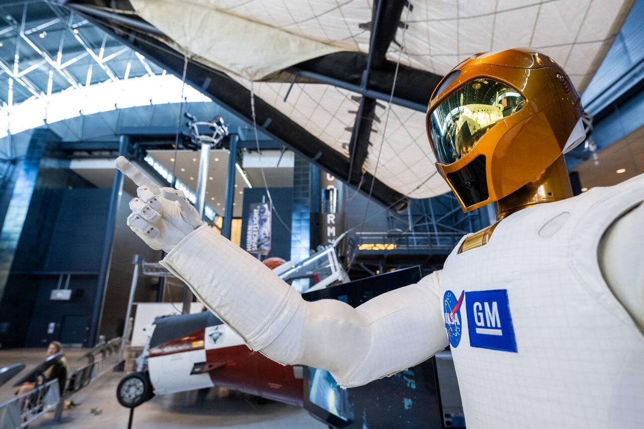 NASA/Keegan Barber. Public domain (NASA / US government work).
Overview
Section titled “Overview”Robonaut 2 is a two-armed anthropomorphic torso developed jointly by NASA Johnson Space Center and General Motors [4]. It is the second of the Robonaut line; Robonaut 1 was a 43 degree-of-freedom design with 7 joints per arm, a 3 degree-of-freedom waist and 14 per hand-and-wrist [4]. NASA’s own project page gives each R2 arm 7 degrees of freedom and a static hold capacity of 20 lb [29].
Specifications
Section titled “Specifications”| Parameter | Value | Source |
|---|---|---|
| Independent degrees of freedom | 42 | [1] |
| Motors | 50 | [1] |
| Sensors | more than 350 | [1] |
| Mass | about 300 kg with climbing legs | |
| Arm joints | 5 per arm, series elastic | |
| Wrist | 2 DOF per wrist | |
| Hand | 12 DOF per hand | |
| Head | 3 DOF | |
| Waist | 1 joint, series elastic | |
| Climbing legs | 7 DOF per leg, 14 total, series elastic |
Rows with no marker are from [2].
Robots in the same role
Section titled “Robots in the same role”Robonaut 2 is one answer to a station workload that mixes crew chores, inspection and maintenance, and the answers split by how much of the human form they keep [26]. The first generation of orbital manipulators, the Shuttle arm, ETS-VII and the Japanese module arm, are large purpose-built arms that work at fixtures designed for them [26]. Robonaut’s premise, stated for Robonaut 1, is the opposite: fit the existing human interfaces and the EVA tool set, work the corridors the crew works, and answer an EVA emergency faster than the several hours an astronaut needs to prebreathe [4]. That premise is why R2 carries a 12 degree-of-freedom hand and a task board of switches, handrails and soft goods, and why its control scheme is built around a human sharing its volume [1], [2].
Free flyers keep the crew’s volume and drop the arms. SPHERES localized by ultrasonic beacons inside a two meter cube and needed manual CO2 and battery swaps every session, which is the argument for Astrobee as an operations tool [14]. Astrobee replaced cold gas with two battery driven impellers and twelve flapper nozzles, and its operators report more than 165 real time operations, more than 90 Guest Science sessions and more than 1200 hours of console support, about 220 of them involving crew [11]. A joint review by members of the Astrobee, CIMON and Int-Ball teams finds that docking-station autonomy separates the flyers that fly often from those that need crew setup [12]. The pre-launch Astrobee papers are charter and design records without measurements, and values such as 0.5 m/s maximum speed and about 10 kg mass are design figures, not flight data [13], [14]. A free flyer cannot grasp a handrail or turn a valve, so the two classes complement each other.
A third approach leaves the dexterous robot on the ground and commands it from orbit. KONTUR-2 closed a bilateral force loop from a 2 degree-of-freedom joystick in the Russian Segment to ground robots over a point-to-point S-band link with 20 to 30 ms round trip [15]. The ground training link measured 65 ms with 5 to 15 percent packet loss [21], and the joystick delivers 15 N at the handle over plus or minus 20 degrees [22]. METERON SUPVIS Justin instead sent task-level commands from a tablet through TDRS at about 800 to 850 ms round trip and 1 Mbit/s, after more than 150 ground runs with 800 ms of injected delay [17]. The experiment was announced with a 2 Mbit/s, 2 to 10 s link budget and a simulated solar farm at DLR as the work site [16], [19]. Three astronauts commanded DLR’s Rollin’ Justin in the first flight session on 25 August 2017 [18], and a session on 2 March 2018 completed a full assembly task [18]. Across both missions nine astronauts and cosmonauts operated ground robots between 2015 and 2018, every protocol succeeded, and no success rate or task time separates the two modalities [15]. METERON Analog-1 added a seven-DOF haptic station with delay compensation, flown in November 2019 and repeated at an Etna field site in 2022 with a retired astronaut on the ground [20]. The link delay sets the choice: haptic telepresence suits tens of milliseconds and supervised autonomy suits seconds [15].
Planetary humanoids sit further from flight. JPL proposed humanoids as habitat builders, with assistants around 2028, but the hardware behind the proposal was a 50 cm HOAP-2 laboratory robot teleoperated for parts of its assembly demonstration [23], [24]. A review of the DARPA Robotics Challenge, the Valkyrie line and electroactive polymer actuators reports no measured comparison across teams [25]. A survey of space construction lists robotics-based assembly without a demonstrated construction task [27]. None of these has flown.
Mission profile
Section titled “Mission profile”| Parameter | Value |
|---|---|
| Host | International Space Station, fixed base stanchion |
| Launch | STS-133, February 2011 |
| Activated on orbit | August 2011 |
| Task board | modular, with powered, unpowered, EVA, stowage and soft goods panels |
| Station tasks demonstrated | handrail cleaning, air velocity measurement |
Source: [3]. R2 arrived on the station on the same STS-133 flight and was mounted as a fixed-base upper body on a stanchion in the US Lab, with climbing legs planned to follow once the task board program was under way [7]; the first crew teleoperation of the arms came in April 2013 [3]. Physical dimensions reported outside the NASA design papers put the torso at 101.6 cm from waist to head and 78.74 cm across the shoulders, at 149.7 kg without the climbing legs, able to lift 9.07 kg in Earth gravity [8].
Actuation
Section titled “Actuation”Joints use brushless DC motors through harmonic drives with series elastic actuation, each joint carrying a planar torsion spring sized individually for that joint and a 19 bit absolute position sensor across it [1]. Torque is measured as spring deflection rather than by a separate load cell, so the same element that provides compliance provides the torque signal.
Robonaut 1 established the torque range the design has to cover: a modular joint family in three torque scales spanning 13.6 to 271 N m (10 to 200 ft-lb), with better than 20 Hz bandwidth in the strain-gauge torque loop [4]. The hand requirement came from the EVA interface standard, 89 N (20 lbf) of force and 3.4 N m (30 in-lb) of torque to remove and install an orbital replacement unit [28]. R1 packaged all fourteen hand and wrist motors, the motor control and power electronics and the hand wiring into a forearm 102 mm (4 in) in diameter at its base and about 203 mm (8 in) long [4].
A closed-loop hand-eye calibration procedure applied to the R1 unit at JSC, fitting Denavit-Hartenberg parameters to stereo camera observations of a tracked sphere, cut the mean mismatch between the kinematic model and the vision system from 13.75 cm to 1.85 cm on the calibration data and to as little as 2.35 cm on held-out configurations [9]. The result registers the two onboard models to each other, not to an external ground truth, and rests on sample sizes of a few dozen to a few hundred configurations [9].
Each hand has five fingers: index and middle at 3 DOF, a 4 DOF thumb, and ring and little fingers at 1 DOF each, 12 DOF in total plus a 2 DOF wrist [1]. The R2 hand reproduces about 90 percent of the Cutkosky grasp taxonomy against about 50 percent for R1, the improvement coming largely from the four-jointed thumb, which is made stronger than the fingers it opposes [1], [5].
The hand is designed against the EVA tool set rather than against purpose-built robot interfaces, and has been operated with sockets, wrenches, drills, wire strippers and flashlights on the ground [1] and with handrails, cables and soft goods on the station [3].
Tactile sensing is carried in a glove rather than in the hand structure. The first generation used 19 Interlink force-sensing resistors of 0.25 inch diameter; the second used 33 pads of quantum tunnelling composite, whose resistance falls from about 10 MOhm to about 1 Ohm across a 0.1 to 10 N force range [5]. With that glove the robot grasped a drill anywhere in a 2 by 1 foot workspace and within plus or minus 5 degrees about two axes.
Compute and data
Section titled “Compute and data”| Element | Specification |
|---|---|
| Central processors | 2 PowerPC cards in a Compact PCI chassis |
| Operating system | VxWorks |
| Software framework | ControlShell |
| Joint controller | Superdriver, FPGA plus PowerPC, per node |
| Distributed nodes | 5 in the upper arm, 2 in forearm and hand |
| Serial bus | MLVDS at 50 Mbit/s |
| Main arm cable | 16 conductors, against more than 100 on R1 |
Source: [1].
Commutation is configurable between six-step and space vector [1]. Reducing the arm cable from over 100 conductors to 16 is a direct consequence of moving commutation and current control into the joint: the cable carries power and a serial bus rather than one pair per phase per motor.
Control
Section titled “Control”Control loops are nested by rate. Current and series-elastic torque control run at 10 kHz in the joint controller [1]; the embedded impedance loop runs at 5 kHz across four consecutive control loops, with 50 Hz the minimum acceptable rate in a degraded mode [2].
The control law is a dual-priority hierarchical impedance scheme: operational-space impedance governs the primary linear and angular task, and joint-space impedance projected into the null space governs the remaining freedom [2]. Gravity, Coriolis and inertia compensation are computed with a recursive Newton-Euler algorithm, and inverse kinematics uses an iterative multi-node pseudo-inverse. Trajectories are trapezoidal in velocity and accept nonzero initial and final conditions.
Impedance is retuned per task rather than fixed. Climbing tests used a stiff setting of natural frequency 20 and damping ratio 1.2 with a 100 torque-unit limit on the base leg and 20 on the reaching leg, against a soft setting of natural frequency 0.5 and damping ratio 1.5 for closing a gripper [2].
A 14 degree-of-freedom hand does not map onto a joystick or a hand-held haptic controller, which motivated a ground demonstration of markerless finger tracking as a teleoperation input: the operator’s hand posture drove the simulated R2 hand directly, with color cues substituting for the missing haptic and contact feedback and the robot advancing only on an explicit operator commit rather than continuous mirroring, to absorb the light-time delay to the station [10]. The demonstration ran entirely against a simulator with idealized grasping and reported no measured task times or error rates, so it establishes the interface concept and not a performance figure [10].
Safety
Section titled “Safety”R2 is certified to work in the same volume as crew without a physical emergency stop, which is replaced by a motion-stop button [1]. Basic torque control limits the force the robot can apply, and separate software monitoring loops read the joint torque sensors and the arm force sensors independently, cutting motor power when either exceeds its limit; further routines on several processors check the health of both loops, giving a triple-redundant force limiting system. The station certification rests on a fail-safe fault containment region approach, in which two demonstrably independent means of failing safe cover each hazard: for inadvertent contact these are the shoulder force sensors and the per-joint absolute position sensors that measure torque in each joint [3]. The safety functions run entirely on the brainstem processors inside the torso, so they remain active if the link to an outside computer is lost.
Mobility
Section titled “Mobility”Climbing legs add 7 series elastic degrees of freedom per leg [2]. In gravity-offload testing a leg reached more than 1 m with better than 1 cm positioning error under full offload [2]. The station program ran the upgrade in phases: intravehicular mobility first, with the climbing legs and a battery backpack, and extravehicular capability after that [3].
Operations on the station
Section titled “Operations on the station”R2 worked a purpose-built task board that flew with it, of modular design with interchangeable panels [3]. The powered panel carries push buttons, two and three way switches, a guarded rocker and a guarded power switch; the unpowered panel carries valves and connectors of the kinds found on station hardware; an EVA panel carries a handrail, a tether point and common EVA fittings; a stowage panel carries restraints; and a soft goods panel carries a fabric-covered box. The board was used repeatedly to practice and refine the motion scripts for generic tasks such as flipping switches, cleaning handrails and handling soft goods, and to test the machine vision that lets R2 verify whether a switch actually moved. Demonstrated station tasks include handrail cleaning and air velocity measurement with the Velocicalc air flow meter, both routine crew chores. Head stereo cameras on a 3 DOF pan and tilt provide the imagery [4], with low-rate visual servoing used to acquire handrails [2].
Extravehicular limits
Section titled “Extravehicular limits”R1 motors were thermal-vacuum rated and the design targeted an 8 hour EVA thermal endurance [4]. Vacuum operation would also expose the harmonic drives and bearings to the lubricant constraints that govern all orbital mechanisms, where vapor pressure rather than viscosity sets the fluid choice [6]. No extravehicular operation of R2 is reported [3].
What is not established
Section titled “What is not established”The orbital record of R2 is narrative: no task success rates, cycle counts or crew-time comparisons are reported for the station tasks [3]. The climbing legs and battery backpack were described before delivery, the 5.79 kWh capacity is a design figure, and the sub-centimeter placement result comes from a gravity-offload facility where only the base leg is offloaded [2], [3]. No flight of the legs is reported [3]. The free flyer and ground-operated robot comparisons above rest on reviews and questionnaires, with no common task metric between R2, Astrobee and the METERON robots [12], [15].
The hand-eye calibration figures for the R1 hand register the robot’s own kinematic and vision models against each other rather than against an external ground truth, on sample sizes of a few dozen to a few hundred configurations [9]. The finger-tracking teleoperation concept for the R2 hand was demonstrated only in simulation, with no measured task times, error rates or characterization of the tracker’s own accuracy, and it was never connected to flight hardware [10]. No EVA thermal or vacuum test of R2 itself is reported; the thermal-vacuum rating and 8 hour endurance figure belong to the R1 design [4], and R2’s own vacuum exposure is not reported.
References
- Diftler, M. A., Radford, N. A., Mehling, J. S., Abdallah, M. E., Bridgwater, L. B., Sanders, A. M., Askew, R. S., Linn, D. M., Yamokoski, J. D., Permenter, F. A. and Hargrave, B. K. (2010). Robonaut 2 - The First Humanoid Robot in Space
. IEEE International Conference on Robotics and Automation, 20100040493. Source
BibTeX
@inproceedings{diftler2010robonaut, title = {Robonaut 2 - The First Humanoid Robot in Space}, author = {Diftler, Myron A. and Radford, N. A. and Mehling, J. S. and Abdallah, M. E. and Bridgwater, L. B. and Sanders, A. M. and Askew, R. S. and Linn, D. M. and Yamokoski, J. D. and Permenter, F. A. and Hargrave, B. K.}, booktitle = {IEEE International Conference on Robotics and Automation}, number = {20100040493}, pages = {2178-2183}, institution = {NASA}, year = {2010}, doi = {10.1109/icra.2011.5979830}, abstract = {NASA and General Motors have developed the second generation Robonaut, Robonaut 2 or R2, and it is scheduled to arrive on the International Space Station in early 2011 and undergo initial testing by mid-year. This state of the art, dexterous, anthropomorphic robotic torso has significant technical improvements over its predecessor making it a far more valuable tool for astronauts. Upgrades include: increased force sensing, greater range of motion, higher bandwidth, and improved dexterity. R2's integrated mechatronic design results in a more compact and robust distributed control system with a fraction of the wiring of the original Robonaut. Modularity is prevalent throughout the hardware and software along with innovative and layered approaches for sensing and control. The most important aspects of the Robonaut philosophy are clearly present in this latest model's ability to allow comfortable human interaction and in its design to perform significant work using the same hardware and interfaces used by people. The following describes the mechanisms, integrated electronics, control strategies, and user interface that make R2 a promising addition to the Space Station and other environments where humanoid robots can assist people.} } - Badger, J. M., Hulse, A. M., Taylor, R. C., Curtis, A. W., Gooding, D. R. and Thackston, A. (2014). Model-based Robotic Dynamic Motion Control for the Robonaut 2 Humanoid Robot
. IEEE-RAS International Conference on Humanoid Robots, 20140000410. Source
BibTeX
@inproceedings{badger2014model, title = {Model-based Robotic Dynamic Motion Control for the Robonaut 2 Humanoid Robot}, author = {Badger, Julia M. and Hulse, Aaron M. and Taylor, Ross C. and Curtis, Andrew W. and Gooding, Dustin R. and Thackston, Allison}, booktitle = {IEEE-RAS International Conference on Humanoid Robots}, number = {20140000410}, pages = {62-67}, institution = {NASA}, year = {2014}, doi = {10.1109/humanoids.2013.7029956}, abstract = {Robonaut 2 (R2), an upper-body dexterous humanoid robot, has been undergoing experimental trials on board the International Space Station (ISS) for more than a year. R2 will soon be upgraded with two climbing appendages, or legs, as well as a new integrated model-based control system. This control system satisfies two important requirements; first, that the robot can allow humans to enter its workspace during operation and second, that the robot can move its large inertia with enough precision to attach to handrails and seat track while climbing around the ISS. This is achieved by a novel control architecture that features a joint-level embedded impedance control law which is tightly interfaced with a kinematic and dynamic coordinated control system that resides on centralized processors. This paper presents the integrated control algorithm as well as several test results that illustrate R2's safety features and performance.} } - Ahlstrom, T. D., Diftler, M. E., Berka, R. B., Badger, J. M., Yayathi, S., Curtis, A. W. and Joyce, C. A. (2013). Robonaut 2 on the International Space Station: Status Update and Preparations for IVA Mobility
. AIAA SPACE Conference. Source
BibTeX
@inproceedings{ahlstrom2013robonaut, title = {Robonaut 2 on the International Space Station: Status Update and Preparations for IVA Mobility}, author = {Ahlstrom, Thomas D. and Diftler, Myron E. and Berka, Reginald B. and Badger, Julia M. and Yayathi, Sandeep and Curtis, Andrew W. and Joyce, Charles A.}, booktitle = {AIAA SPACE Conference}, address = {San Diego, California}, year = {2013}, doi = {10.2514/6.2013-5340}, abstract = {Robotics engineers, ground controllers and International Space Station (ISS) crew have been running successful experiments using Robonaut 2 (R2) on-board the ISS for more than a year. This humanoid upper body robot continues to expand its list of achievements and its capabilities to safely demonstrate maintenance and servicing tasks while working alongside human crewmembers. The next phase of the ISS R2 project will transition from a stationary Intra Vehicular Activity (IVA) upper body using a power/data umbilical, to an IVA mobile system with legs for repositioning, a battery backpack power supply, and wireless communications. These upgrades will enable the R2 team to evaluate hardware performance and to develop additional control algorithms and control verification techniques with R2 inside the ISS in preparation for the Extra Vehicular Activity (EVA) phase of R2 operations. As R2 becomes more capable in assisting with maintenance tasks, with minimal supervision, including repositioning itself to different work sites, the ISS crew will be burdened with fewer maintenance chores, leaving them more time to conduct other activities. R2's developers at the Johnson Space Center (JSC) are preparing the R2 IVA mobility hardware and software upgrades for delivery to the ISS in late 2013. This paper summarizes R2 ISS achievements to date, briefly describes the R2 IVA mobility upgrades, and discusses the R2 IVA mobility objectives and plans.} } - Ambrose, R. O. and Diftler, M. A. (2001). Robonaut: A Robotic Astronaut Assistant
. International Symposium on Artificial Intelligence, Robotics and Automation in Space, 20100033240. Source
BibTeX
@inproceedings{ambrose2001robonaut, title = {Robonaut: A Robotic Astronaut Assistant}, author = {Ambrose, Robert O. and Diftler, Myron A.}, booktitle = {International Symposium on Artificial Intelligence, Robotics and Automation in Space}, number = {20100033240}, institution = {NASA}, address = {Montreal}, year = {2001}, url = {https://ntrs.nasa.gov/citations/20100033240}, abstract = {NASA's latest anthropomorphic robot, Robonaut, has reached a milestone in its capability. This highly dexterous robot, designed to assist astronauts in space, is now performing complex tasks at the Johnson Space Center that could previously only be carried out by humans. With 43 degrees of freedom, Robonaut is the first humanoid built for space and incorporates technology advances in dexterous hands, modular manipulators, lightweight materials, and telepresence control systems. Robonaut is human size, has a three degree of freedom (DOF) articulated waist, and two, seven DOF arms, giving it an impressive work space for interacting with its environment. Its two, five fingered hands allow manipulation of a wide range of tools. A pan/tilt head with multiple stereo camera systems provides data for both teleoperators and computer vision systems.} } - Martin, T. B., Ambrose, R. O., Diftler, M. A., Platt, R. J. and Butzer, M. J. (2004). Tactile Gloves for Autonomous Grasping With the NASA/DARPA Robonaut
. NASA, 20050236770. Source
BibTeX
@techreport{martin2004tactile, title = {Tactile Gloves for Autonomous Grasping With the NASA/DARPA Robonaut}, author = {Martin, T. B. and Ambrose, Robert O. and Diftler, Myron A. and Platt, R., Jr. and Butzer, M. J.}, number = {20050236770}, institution = {NASA}, year = {2004}, doi = {10.21236/ada438799}, abstract = {Tactile data from rugged gloves are providing the foundation for developing autonomous grasping skills for the NASA/DARPA Robonaut, a dexterous humanoid robot. These custom gloves compliment the human like dexterity available in the Robonaut hands. Multiple versions of the gloves are discussed, showing a progression in using advanced materials and construction techniques to enhance sensitivity and overall sensor coverage. The force data provided by the gloves can be used to improve dexterous, tool and power grasping primitives. Experiments with the latest gloves focus on the use of tools, specifically a power drill used to approximate an astronaut's torque tool.} } - Jones, W. R. J., Jansen, M. J., Gschwender, L. J., Snyder, C. E. J., Sharma, S. K., Predmore, R. E. and Dube, M. J. (2001). The Tribological Properties of Several Silahydrocarbons for Use in Space Mechanisms
. Journal of Synthetic Lubrication, NASA/TM-2001-211196. Source
BibTeX
@article{jones2001tribological, title = {The Tribological Properties of Several Silahydrocarbons for Use in Space Mechanisms}, author = {Jones, W. R., Jr. and Jansen, M. J. and Gschwender, L. J. and Snyder, C. E., Jr. and Sharma, Shiv K. and Predmore, R. E. and Dube, Michael J.}, journal = {Journal of Synthetic Lubrication}, volume = {20}, number = {NASA/TM-2001-211196}, pages = {303-315}, institution = {NASA}, address = {Liege}, year = {2001}, doi = {10.1002/jsl.3000200404}, abstract = {Abstract Silahydrocarbons are members of a relatively new class of liquid lubricants with great potential for use in space mechanisms. They are unimolecular species consisting of silicon, carbon, and hydrogen. They possess unique wear, viscosity, and volatility properties while retaining the ability to solubilise conventional additives. The tribological properties of several members of this class, including tri‐, tetra‐, and penta‐compounds, are presented. These properties include viscosity‐temperature, viscosity—pressure, vapour pressure, lubricant life, traction, and reciprocating and four‐ball wear rates. Lubricant lifetimes were determined using a vacuum ball bearing simulator, the spiral orbit tribometer. Wear was measured using a Cameron Plint reciprocating tribometer and wear rates with a vacuum four‐ball tribometer. Conventional viscometry was used for viscosity—temperature measurements and a Knudsen cell for vapour pressure. Thermogravimetric analysis was also used for volatility measurements. Pressure—viscosity coefficients (α—values) were estimated from elastohydrodynamic lubrication film thickness measurements. These properties are compared to those of existing state‐of‐the‐art space lubricants.} } - Diftler, M. A., Greene, B. D., Joyce, C., De La Pena, N., Noblitt, A. and Ambrose, R. (2011). Robonaut 2 - Initial Activities On-Board the ISS
. IEEE Aerospace Conference, 20110023640. Source
BibTeX
@inproceedings{diftler2011robonaut, title = {Robonaut 2 - Initial Activities On-Board the ISS}, author = {Diftler, Myron A. and Greene, B. D. and Joyce, Charles and De La Pena, Noe and Noblitt, Alan and Ambrose, Robert}, booktitle = {IEEE Aerospace Conference}, number = {20110023640}, institution = {NASA}, address = {Big Sky, Montana}, year = {2011}, url = {https://ntrs.nasa.gov/citations/20110023640}, abstract = {Robonaut 2, or R2, arrived on the International Space Station in February 2011 and is currently undergoing testing in preparation for it to become, initially, an Intra-Vehicular Activity (IVA) tool and then evolve into a system that can perform Extra-Vehicular Activities (EVA). After the completion of a series of system level checks to ensure that the robot traveled well on-board the Space Shuttle Atlantis, ground control personnel will remotely control the robot to perform free space tasks that will help characterize the differences between earth and zero-g control. For approximately one year, the fixed base R2 will perform a variety of experiments using a reconfigurable task board that was launched with the robot. While working side-by-side with human astronauts, Robonaut 2 will actuate switches, use standard tools, and manipulate Space Station interfaces, soft goods and cables. The results of these experiments will demonstrate the wide range of tasks a dexterous humanoid can perform in space and they will help refine the methodologies used to control dexterous robots both in space and here on earth. After the trial period that will evaluate R2 while on a fixed stanchion in the US Laboratory module, NASA plans to launch climbing legs that when attached to the current on-orbit R2 upper body will give the robot the ability to traverse through the Space Station and start assisting crew with general IVA maintenance activities. Multiple control modes will be evaluated in this extra-ordinary ISS test environment to prepare the robot for use during EVAs. Ground Controllers will remotely supervise the robot as it executes semi-autonomous scripts for climbing through the Space Station and interacting with IVA interfaces. IVA crew will locally supervise the robot using the same scripts and also teleoperate the robot to simulate scenarios with the robot working alone or as an assistant during space walks.} } - Klyushnikov, V. Y. (2020). Robot Avatar: A Means of Human Telepresence in Space
. Aerospace Sphere Journal, 1. Source
BibTeX
@article{klyushnikov2020robot, title = {Robot Avatar: A Means of Human Telepresence in Space}, author = {Klyushnikov, Valery Y.}, journal = {Aerospace Sphere Journal}, volume = {102}, number = {1}, pages = {60--69}, year = {2020}, doi = {10.30981/2587-7992-2020-102-1-60-69}, abstract = {АННОТАЦИЯ I В статье проведен анализ перспектив создания и практического использования технологии роботов-аватаров, предназначенных для исследования, освоения и использования космоса.Определен возможный облик аватара и системы сопряжения робота-аватара с человеком-оператором.} } - Nickels, K., Huber, E. and DiCicco, M. (2007). Hand-eye calibration using active vision. dataverse.jpl.nasa.gov/dataset.xhtml
BibTeX
@misc{nickels2007hand, title = {Hand-eye calibration using active vision}, author = {Nickels, Kevin and Huber, Eric and DiCicco, Matthew}, year = {2007}, url = {https://dataverse.jpl.nasa.gov/dataset.xhtml?persistentId=hdl:2014/41844} } - Champoux, R. G. (2012). Teleoperation of robonaut using finger tracking
. Smart Structures and Materials Symposium. Source
BibTeX
@inproceedings{champoux2012teleoperation, title = {Teleoperation of robonaut using finger tracking}, author = {Champoux, Rachel G.}, booktitle = {Smart Structures and Materials Symposium}, publisher = {JPL Open Repository}, year = {2012}, url = {https://dataverse.jpl.nasa.gov/dataset.xhtml?persistentId=hdl:2014/43142} } - Alexandrov, O., Barlow, J., Benavides, J., Bualat, M., Carlino, R., Coltin, B., Cortez, J., Daley, E., Feller, J., Flückiger, L., Fong, T., Fusco, J., Garcia Ruiz, R., Hamilton, K., Kanis, S., Katterhagen, A., Kim, Y., Love, J. F., McIntyre, M., McLachlan, B., Mora Vargas, A., Moratto, Z., Moreira, M., Morse, T., Orosco, H., Park, I.-W., Provencher, C., Sanchez, H., Sharif, K., Smith, E., Smith, T., Soussan, R., Symington, A., Talavera, R. O., To, V., Wheeler, D. and Yoo, J. (2026). Astrobee: Free-Flying Robots for the International Space Station
. IEEE Transactions on Field Robotics. Source
BibTeX
@article{alexandrov2026astrobee, title = {Astrobee: Free-Flying Robots for the International Space Station}, author = {Alexandrov, Oleg and Barlow, Jonathan and Benavides, Jose and Bualat, Maria and Carlino, Roberto and Coltin, Brian and Cortez, Jose and Daley, Earl and Feller, Jeffrey and Flückiger, Lorenzo and Fong, Terrence and Fusco, Jesse and Garcia Ruiz, Ruben and Hamilton, Kathryn and Kanis, Simeon and Katterhagen, Aric and Kim, Yunkyung and Love, John F. and McIntyre, Michael and McLachlan, Blair and Mora Vargas, Andres and Moratto, Zack and Moreira, Marina and Morse, Theodore and Orosco, Henry and Park, In-Won and Provencher, Christopher and Sanchez, Hugo and Sharif, Khaled and Smith, Ernest and Smith, Trey and Soussan, Ryan and Symington, Andrew and Talavera, Rafael Omar and To, Vinh and Wheeler, DW and Yoo, Jongwoon}, journal = {IEEE Transactions on Field Robotics}, year = {2026}, url = {https://ntrs.nasa.gov/citations/20260001396}, abstract = {The Astrobees are free-flying robots that operate inside the International Space Station (ISS) and were launched to the ISS in 2019. Since then they have successfully performed hundreds of activities in space supporting almost two dozen separate research projects. The robots were designed to overcome multiple challenges unique to the ISS environment, including safety, upgradeability and maintainability, limited mass and computation, and unique localization challenges from lack of gravity and a constantly changing environment. This article provides an overview of Astrobee, from hardware and software design to deployment results and activities.} } - Yamaguchi, S. P., Mora Vargas, A., Eisenberg, T., Rogon, C., Yamamoto, T., Inoue, S., Kössl, C., Coltin, B., Smith, T. and Benavides, J. V. (2025). Free-Flying Crew Cooperative Robots on the ISS: A Joint Review of Astrobee, CIMON, and Int-Ball Operations
. International Conference on Space Robotics. Source
BibTeX
@inproceedings{yamaguchi2026free, title = {Free-Flying Crew Cooperative Robots on the ISS: A Joint Review of Astrobee, CIMON, and Int-Ball Operations}, author = {Yamaguchi, Seiko Piotr and Mora Vargas, Andres and Eisenberg, Till and Rogon, Christian and Yamamoto, Tatsuya and Inoue, Shona and Kössl, Christoph and Coltin, Brian and Smith, Trey and Benavides, Jose V.}, booktitle = {International Conference on Space Robotics}, pages = {402-409}, year = {2025}, doi = {10.1109/isparo66239.2025.11436992}, abstract = {Intra-vehicular free-flying robots are anticipated to support various work in human spaceflight while working side-by-side with astronauts. Such example of robots includes NASA’s Astrobee, DLR’s CIMON, and JAXA’s Int-Ball, which are deployed on the International Space Station. This paper presents the first joint analyses of these robot’s shared experiences, co-authored by their development and operation team members. Despite the different origins and design philosophies, the development and operations of these platforms encountered various convergences. Hence, this paper presents a detailed overview of these robots, presenting their objectives, design, and onboard operations. Hence, joint lessons learned across the lifecycle are presented, from design to on-orbit operations. These lessons learned are anticipated to serve for future development and research as design recommendations.} } - Bualat, M., Barlow, J., Fong, T., Provencher, C., Smith, T. and Zuniga, A. (2015). Astrobee: Developing a Free Flying Robot for the International Space Station
. AIAA SPACE Conference, 20150018250. Source
BibTeX
@inproceedings{bualat2015astrobee, title = {Astrobee: Developing a Free Flying Robot for the International Space Station}, author = {Bualat, Maria and Barlow, Jonathan and Fong, Terrence and Provencher, Christopher and Smith, Trey and Zuniga, Allison}, booktitle = {AIAA SPACE Conference}, number = {20150018250}, institution = {NASA}, year = {2015}, doi = {10.2514/6.2015-4643}, abstract = {Astronaut time will always be in short supply, consumables (e.g., oxygen) will always be limited, and some work will not be feasible, or productive, for astronauts to do manually. Free flyers offer significant potential to perform a great variety of tasks, include routine, repetitive or simple but long-duration work, such as conducting environment surveys, taking sensor readings or monitoring crew activities. The "Astrobee" project is developing a new free flying robot system suitable for performing Intravehicular Activity (IVA) work on the International Space Station (ISS). This paper will describe the Astrobee project objectives, initial design, concept of operations, and key challenges.\n\n\n} } - Bualat, M. G., Smith, T., Fong, T. W., Smith, E. E. and Wheeler, D. W. (2018). Astrobee: A New Tool for ISS Operations
. SpaceOps Conference. Source
BibTeX
@inproceedings{bualat2018astrobee, title = {Astrobee: A New Tool for ISS Operations}, author = {Bualat, Maria G. and Smith, Trey and Fong, Terrence W. and Smith, Ernest E. and Wheeler, D. W.}, booktitle = {SpaceOps Conference}, address = {Marseille, France}, year = {2018}, doi = {10.2514/6.2018-2517}, abstract = {The Astrobee} } - Lii, N. Y., Riecke, C., Leidner, D., Schätzle, S., Schmaus, P., Weber, B., Krueger, T., Stelzer, M., Wedler, A. and Grunwald, G. (2018). The Robot as an Avatar or Co-worker? An Investigation of the Different Teleoperation Modalities through the KONTUR-2 and METERON SUPVIS Justin Space Telerobotic Missions
. International Astronautical Congress, IAC-18-B3.6-A5.3.5x47302. Source
BibTeX
@inproceedings{lii2018robot, title = {The Robot as an Avatar or Co-worker? An Investigation of the Different Teleoperation Modalities through the KONTUR-2 and METERON SUPVIS Justin Space Telerobotic Missions}, author = {Lii, Neal Y. and Riecke, Cornelia and Leidner, Daniel and Schätzle, Simon and Schmaus, Peter and Weber, Bernhard and Krueger, Thomas and Stelzer, Martin and Wedler, Armin and Grunwald, Gerhard}, booktitle = {International Astronautical Congress}, number = {IAC-18-B3.6-A5.3.5x47302}, year = {2018}, url = {https://elib.dlr.de/133023/} } - Lii, N. Y., Leidner, D., Schiele, A., Birkenkampf, P., Pleintinger, B. and Bayer, R. (2015). Command Robots from Orbit with Supervised Autonomy
. SAE Technical Paper Series. Source
BibTeX
@inproceedings{lii2015command, title = {Command Robots from Orbit with Supervised Autonomy}, author = {Lii, Neal Y. and Leidner, Daniel and Schiele, André and Birkenkampf, Peter and Pleintinger, Benedikt and Bayer, Ralph}, booktitle = {SAE Technical Paper Series}, pages = {53-54}, publisher = {ACM}, year = {2015}, doi = {10.1145/2701973.2702022}, abstract = {The on-going work at German Aerospace Center (DLR) and European Space Agency (ESA) on the Meteron Supvis-Justin space telerobotic experiment utilizing supervised autonomy is presented. The Supvis-Justin experiment will employ a tablet UI for an astronaut on the International Space Station (ISS) to communicate task level commands to a service robot. The goal is to explore the viability of supervised autonomy for space telerobotics. For its validation, survey, navigation, inspection, and maintenance tasks will be commanded to DLR's service robot, Rollin' Justin, to be performed in a simulated extraterrestrial environment constructed at DLR. The experiment is currently slated for late 2015-2016.} } - Lii, N. Y., Leidner, D., Birkenkampf, P., Pleintinger, B., Bayer, R. and Krueger, T. (2017). Toward Scalable Intuitive Teleoperation of Robots for Space Deployment with the METERON SUPVIS Justin Experiment
. Symposium on Advanced Space Technologies in Robotics and Automation. Source
BibTeX
@inproceedings{lii2017scalable, title = {Toward Scalable Intuitive Teleoperation of Robots for Space Deployment with the METERON SUPVIS Justin Experiment}, author = {Lii, Neal Y. and Leidner, Daniel and Birkenkampf, Peter and Pleintinger, Benedikt and Bayer, Ralph and Krueger, Thomas}, booktitle = {Symposium on Advanced Space Technologies in Robotics and Automation}, year = {2017}, url = {https://elib.dlr.de/113125/} } - Schmaus, P., Leidner, D., Bayer, R., Pleintinger, B., Krüger, T. and Lii, N. Y. (2019). Continued Advances in Supervised Autonomy User Interface Design for METERON SUPVIS Justin
. IEEE Aerospace Conference. Source
BibTeX
@inproceedings{schmaus2019continued, title = {Continued Advances in Supervised Autonomy User Interface Design for METERON SUPVIS Justin}, author = {Schmaus, Peter and Leidner, Daniel and Bayer, Ralph and Pleintinger, Benedikt and Krüger, Thomas and Lii, Neal Y.}, booktitle = {IEEE Aerospace Conference}, pages = {1-11}, address = {Big Sky, Montana}, year = {2019}, doi = {10.1109/aero.2019.8741885}, abstract = {The exploration of the universe remains a challenging endeavor, constantly pushing the limits of technology. Of special interest is the investigation of the other planets of our solar system such as Mars, which has been examined by various tele-operated and (semi-) autonomous satellites and landers. But an important milestone that is needed for a deeper understanding of the planet is still missing: A crewed landing. In order to send humans to such a remote location, an infrastructure for the landing crew including an energy supply, a habitat, and a return vehicle needs to be provided on the surface of the planet. The construction and maintenance of these structures is envisioned to be done by semiautonomous robots that are commanded from orbiting spacecrafts. The teleoperation of such ground-based robots poses high demands on the capabilities of the system including robot autonomy, orbiter-robot communication, and human-robot interface design. The METERON SVPVIS Justin space telerobotics experiment suite has been initiated by the German Aerospace Center (DLR) together with the European Space Agency (ESA) to investigate the requirements for such a system and evaluate an approach. During the experiment sessions, astronauts onboard the International Space Station (ISS) command DLR's humanoid service robot Rollin' Justin on Earth to execute complex surveillance, service, and repair tasks in a simulated Martian solar farm. The robot uses its local intelligence to support the astronaut operator upon task completion allowing a simple intuitive command interface and lowering the requirements on the communication link. This work gives an overview of the developed robotic system, communication link, and tablet computer user interface (UI). In particular the tight coupling between the autonomy system of the robot and the UI, that allows the intuitive robot commanding including action parameterization, is described in detail. The first space-ground experiment sessions of METERON SUPVIS Justin were conducted in August 2017, and March 2018 by four astronauts in total. During the first session, three astronauts demonstrated the operational readiness of our system by commanding Rollin' Justin to perform surveillance and inspection tasks. The astronauts were even able to successfully command the robot in scenarios, which were not trained prior to their spaceflight. This was possible, because our astronaut-robot collaboration concept efficiently guides the operator towards task completion. We used this property in the second experiment session to evaluate our system in even more complex scenarios. While in the first session it was sufficient for the astronaut to select the correct commands, the operator was now required to manually parameterize some of the commands to optimize the task outcome. By that, the robot has been successfully commanded to perform complex maintenance and adjustment tasks in the simulated Martian solar farm. In this work, we evaluate the preliminary results of the space-ground experiments and discuss the feedback we received from the astronauts and its impact on future space telerobotics UI design.} } - Lii, N. Y., Leidner, D., Schiele, A., Birkenkampf, P., Pleintinger, B. and Bayer, R. (2015). Simulating an Extraterrestrial Environment for Robotic Space Exploration: The METERON SUPVIS-Justin Telerobotic Experiment and the SOLEX Proving Ground
. Symposium on Advanced Space Technologies in Robotics and Automation. Source
BibTeX
@inproceedings{lii2015simulating, title = {Simulating an Extraterrestrial Environment for Robotic Space Exploration: The METERON SUPVIS-Justin Telerobotic Experiment and the SOLEX Proving Ground}, author = {Lii, Neal Y. and Leidner, Daniel and Schiele, André and Birkenkampf, Peter and Pleintinger, Benedikt and Bayer, Ralph}, booktitle = {Symposium on Advanced Space Technologies in Robotics and Automation}, year = {2015}, url = {https://elib.dlr.de/98352/} } - Carey, W., Krueger, T., Wormnes, K., Grenouilleau, J., Ferreira, E., Nergaard, K., van der Hulst, F., den Exter, E. and Gerdes, L. (2022). METERON Analog-1: A Touch Remote
. International Astronautical Congress, IAC-22-A3.2B.4. Source
BibTeX
@inproceedings{carey2022meteron, title = {METERON Analog-1: A Touch Remote}, author = {Carey, William and Krueger, Thomas and Wormnes, Kjetil and Grenouilleau, Jessica and Ferreira, Edmundo and Nergaard, Kim and van der Hulst, Frank and den Exter, Emiel and Gerdes, Levin}, booktitle = {International Astronautical Congress}, number = {IAC-22-A3.2B.4}, year = {2022}, url = {https://elib.dlr.de/190115/} } - Artigas, J., Riecke, C., Weber, B., Stelzer, M., Balachandran, R., Schaetzle, S., Bayer, R., Steinmetz, B.-M., Vogel, J., Brunner, B., Albu-Schäffer, A., Guk, M., Zaborovskyi, V., Kondratiev, A., Muliukha, V., Silinenko, A. and Shmakov, O. (2016). Force-Feedback Teleoperation of On-Ground Robots from the International Space Station in the Frame of the KONTUR-2 Experiment
. International Symposium on Artificial Intelligence, Robotics and Automation in Space. Source
BibTeX
@inproceedings{artigas2016force, title = {Force-Feedback Teleoperation of On-Ground Robots from the International Space Station in the Frame of the KONTUR-2 Experiment}, author = {Artigas, Jordi and Riecke, Cornelia and Weber, Bernhard and Stelzer, Martin and Balachandran, Ribin and Schaetzle, Simon and Bayer, Ralph and Steinmetz, Bernhard-Michael and Vogel, Jörg and Brunner, Bernhard and Albu-Schäffer, Alin and Guk, M. and Zaborovskyi, V. and Kondratiev, A. and Muliukha, V. and Silinenko, A. and Shmakov, O.}, booktitle = {International Symposium on Artificial Intelligence, Robotics and Automation in Space}, pages = {1166-1173}, year = {2016}, doi = {10.1109/icra.2016.7487246}, abstract = {This paper presents a new robot controller for space telerobotics missions specially designed to meet the requirements of KONTUR-2, a German & Russian telerobotics mission that addressed scientific and technological questions for future planetary explorations. In KONTUR-2, Earth and ISS have been used as a test-bed to evaluate and demonstrate a new technology for real-time telemanipulation from space. During the August 2015' experiments campaign, a cosmonaut teleoperated a robot manipulator located in Germany, using a force-feedback joystick from the Russian segment of the International Space Station (ISS). The focus of the paper is on the design and performance of the bilateral controller between ISS joystick and Earth robot. The controller is based on a 4-Channels architecture in which stability is guaranteed through passivity and the Time Delay Power Network (TDPN) concept. We show how the proposed approach successfully fulfills mission requirements, specially those related to system operation through space links and internet channels, involving time delays and data losses of different nature.} } - Riecke, C., Artigas, J., Balachandran, R., Bayer, R., Beyer, A., Brunner, B., Buchner, H., Gumpert, T., Gruber, R., Hacker, F., Landzettel, K., Plank, G., Schätzle, S., Sedlmayr, H.-J., Seitz, N., Steinmetz, B.-M., Stelzer, M., Vogel, J., Weber, B., Willberg, B. and Albu-Schäffer, A. (2016). KONTUR-2 Mission: The DLR Force Feedback Joystick for Space Telemanipulation from the ISS
. International Symposium on Artificial Intelligence, Robotics and Automation in Space. Source
BibTeX
@inproceedings{riecke2016kontur, title = {KONTUR-2 Mission: The DLR Force Feedback Joystick for Space Telemanipulation from the ISS}, author = {Riecke, Cornelia and Artigas, Jordi and Balachandran, Ribin and Bayer, Ralph and Beyer, Alexander and Brunner, Bernhard and Buchner, Hans and Gumpert, Thomas and Gruber, Robin and Hacker, Franz and Landzettel, Klaus and Plank, Georg and Schätzle, Simon and Sedlmayr, Hans-Jürgen and Seitz, Nikolaus and Steinmetz, Bernhard-Michael and Stelzer, Martin and Vogel, Jörg and Weber, Bernhard and Willberg, Bertram and Albu-Schäffer, Alin}, booktitle = {International Symposium on Artificial Intelligence, Robotics and Automation in Space}, year = {2016}, url = {https://elib.dlr.de/105449/} } - Stoica, A., Keymeulen, D., Csaszar, A., Gan, Q., Hidalgo, T., Moore, J., Newton, J., Sandoval, S. and Xu, J. (2005). Humanoids for lunar and planetary surface operations
. IEEE-RAS International Conference on Humanoid Robots. Source
BibTeX
@inproceedings{stoica2005humanoids, title = {Humanoids for lunar and planetary surface operations}, author = {Stoica, Adrian and Keymeulen, Didier and Csaszar, Ambrus and Gan, Quan and Hidalgo, Timothy and Moore, Jeff and Newton, Jason and Sandoval, Steven and Xu, Jiajing}, booktitle = {IEEE-RAS International Conference on Humanoid Robots}, pages = {345}, publisher = {IEEE}, year = {2005}, doi = {10.1109/ichr.2005.1573591}, abstract = {This paper presents a vision of humanoid robots as human's key partners in future space exploration, in particular for construction, maintenance/repair and operation of lunar/planetary habitats, bases and settlements. It integrates this vision with the recent plans for human and robotic exploration, aligning a set of milestones for operational capability of humanoids with the schedule and phases of human space flight system development program for the next decades. These milestones relate to a set of incremental challenges, for the solving of which new humanoid technologies are needed. A system of systems integrative approach that would lead to readiness of cooperating humanoid crews is sketched. Robot fostering, training/education techniques, and improved cognitive/sensory/motor development techniques are considered essential elements for achieving intelligent humanoids. A pilot project in this direction is outlined.} } - Keymeulen, D., Myers, J., Newton, J., Csaszar, A., Gan, Q., Hidalgo, T., Moore, J., Sandoval, S., Xu, J., Schon, A., Assad, C. and Stoica, A. (2006). Humanoids for lunar and planetary surface operations. doi.org/10.1109/icsmc.2005.1571549
BibTeX
@misc{keymeulen2006humanoids, title = {Humanoids for lunar and planetary surface operations}, author = {Keymeulen, Didier and Myers, John and Newton, Jason and Csaszar, Ambrus and Gan, Quan and Hidalgo, Tim and Moore, Jeff and Sandoval, Steven and Xu, Jiajing and Schon, Aaron and Assad, Chris and Stoica, Adrian}, howpublished = {Presentation at the IEEE International Conference on Systems, Man and Cybernetics}, volume = {3}, pages = {2649-2654}, year = {2006}, doi = {10.1109/icsmc.2005.1571549} } - Bar-Cohen, Y. (2016). Humanoids and the potential role of electroactive materials/mechanisms in advancing their capability
. Forum on New Materials - Part A. Source
BibTeX
@inproceedings{barcohen2016humanoids, title = {Humanoids and the potential role of electroactive materials/mechanisms in advancing their capability}, author = {Bar-Cohen, Yoseph}, booktitle = {Forum on New Materials - Part A}, volume = {97}, pages = {81-89}, year = {2016}, doi = {10.4028/www.scientific.net/ast.97.81}, abstract = {Humanoids are increasingly becoming capable biologically inspired robots that are appearing and behaving lifelike. Making humanlike robots is the ultimate challenge to biomimetics and, while for many years they were considered a science fiction, such robots are increasingly becoming engineering reality. Progress in producing such robots are allowing them to perform impressive functions and tasks. In 2012, in an effort to promote significant advances in developing humanoids, DARPA posed a Robotic Challenge to produce such robots that operate in disaster scenarios towards making society more resilient. The challenge was focused on the requirements that have been needed after the Fukushima accident in Japan, hoping to advance the field of disaster robotics. This disaster posed significant challenges to emergency responders since radiation prevented people from going into the station and venting the explosive gas. Another significant development in this field is the fact that major US corporations have entered into the race to produce commercial humanoids. As a result, one can expect significant and rapid progress in this field. Developing humanoids is critically dependent of the use of highly efficient, compact, lightweight actuators and electroactive materials are offering great potential. This paper reviews the state-of-the-art of humanlike robots, potential applications and challenges, as well as the actuation materials that are used or could be used.} } - Yoshida, K., Wilcox, B., Hirzinger, G. and Lampariello, R. (2016). Space Robotics
. Springer Handbook of Robotics. Source
BibTeX
@incollection{yoshida2016space, title = {Space Robotics}, author = {Yoshida, Kazuya and Wilcox, Brian and Hirzinger, Gerd and Lampariello, Roberto}, booktitle = {Springer Handbook of Robotics}, series = {Springer Handbooks}, pages = {1423-1462}, publisher = {Springer International Publishing}, year = {2016}, doi = {10.1007/978-3-319-32552-1_55} } - Howe, A. S. and Colombano, S. P. (2010). The challenge of space infrastructure construction
. AIAA SPACE Conference. Source
BibTeX
@inproceedings{howe2010challenge, title = {The challenge of space infrastructure construction}, author = {Howe, A. Scott and Colombano, Silvano P.}, booktitle = {AIAA SPACE Conference}, year = {2010}, doi = {10.2514/6.2010-8619}, abstract = {This paper reviews the range of technologies that will contribute to the construction of space infrastructure that will both enable and, in some cases, provide the motivation for space exploration. Five parts are addressed: Managing complexity, robotics based construction, materials acquisition, manufacturing, and self-sustaining systems.} } - Bluethmann, W., Ambrose, R., Diftler, M., Askew, S., Huber, E., Goza, M., Rehnmark, F., Lovchik, C. and Magruder, D. (2003). Robonaut: a robot designed to work with humans in space
. Autonomous Robots, 20040087729. Source
BibTeX
@article{bluethmann2003robonaut, title = {Robonaut: a robot designed to work with humans in space}, author = {Bluethmann, William and Ambrose, Robert and Diftler, Myron and Askew, Scott and Huber, Eric and Goza, Michael and Rehnmark, Fredrik and Lovchik, Chris and Magruder, Darby}, journal = {Autonomous Robots}, volume = {14}, number = {20040087729}, pages = {179-197}, institution = {NASA}, year = {2003}, doi = {10.1023/a:1022231703061}, abstract = {The Robotics Technology Branch at the NASA Johnson Space Center is developing robotic systems to assist astronauts in space. One such system, Robonaut, is a humanoid robot with the dexterity approaching that of a suited astronaut. Robonaut currently has two dexterous arms and hands, a three degree-of-freedom articulating waist, and a two degree-of-freedom neck used as a camera and sensor platform. In contrast to other space manipulator systems, Robonaut is designed to work within existing corridors and use the same tools as space walking astronauts. Robonaut is envisioned as working with astronauts, both autonomously and by teleoperation, performing a variety of tasks including, routine maintenance, setting up and breaking down worksites, assisting crew members while outside of spacecraft, and serving in a rapid response capacity.} } - (2023). NASA: Robonaut 2. nasa.gov/robonaut2
BibTeX
@misc{nasarobonaut,
  title = {NASA: Robonaut 2},
  organization = {nasa.gov},
  year = {2023},
  url = {https://www.nasa.gov/robonaut2}
}