ESA ESTEC Automation and Robotics Laboratories
ESA / G. Porter. CC BY-SA IGO.
The Automation and Robotics Laboratories are the robotics laboratories of the European Space Research and Technology Centre at Noordwijk, run by the Automation and Robotics Section of ESA’s Directorate of Technology, Engineering and Quality. Four laboratories sit under that heading: the Orbital Robotics Laboratory, the Planetary Robotics Laboratory, the Human Robot Interaction Laboratory and the Regolith Interaction Facility. The group holds ISO 9001:2008 certification [1].
What a robotics campaign gets here is a 9 by 9 m indoor terrain bed for locomotion, navigation and arm placement; a 45 m2 air bearing flat floor that relieves two translational and one rotational degree of freedom for rendezvous, docking and capture work; and a small dusty thermal vacuum chamber in which a wheel, a drill or a joint meets regolith at vacuum and at lunar temperatures [2][3].
ESTEC houses two distinct organizations. The robotics laboratories belong to the Directorate of Technology, Engineering and Quality and are entered through ESA’s Third Party Activities route [1]. The Test Centre is a separate 6000 square meter cleanroom complex operated under contract by European Test Services on ESA’s behalf, holding Europe’s largest vacuum chamber, its loudest acoustic facility and its most powerful hydraulic shaker [14]. Its Large Space Simulator has its own page, a different operator and a different access route.
Laboratory data
Section titled “Laboratory data”| Parameter | Value |
|---|---|
| Operator | ESA Automation and Robotics Section, Directorate of Technology, Engineering and Quality, ESTEC [1] |
| Location | Keplerlaan 1, 2201 AZ Noordwijk, the Netherlands [3] |
| Commissioned | Terrain bed in service by 2013 [2]; ORBIT floor built and characterized 2015 to 2016 [3] |
| Type | Indoor robotics laboratories: terrain bed, air bearing flat floor, dusty thermal vacuum chamber [1] |
| Floor area | Terrain bed 81 m2; ORBIT floor 45 m2 [2][3] |
| Capabilities | Mars Yard, PUT, ORBIT, DTVAC |
| Simulant or terrain | Sand, gravel and rock in the yard; simulant bed in DTVAC. Tonnages not published [1][2] |
| Instrumentation | Vicon on ORBIT [3]; infrared motion tracking in the yard [2]; RIEGL and Nikon metrology [1] |
| Ground truth | Motion capture and laser scanning, independent of the article under test |
| Fidelity limits | No vacuum, thermal or offload capability in the yard; DTVAC bed 0.5 x 0.5 x 0.2 m [1] |
| Access | ESA Third Party Activities; ORBIT also through the ESA Academy Experiments Programme [1][11] |
| Cited by | rosalind-franklin |
The laboratories maintain their own rover testbeds rather than relying on visiting hardware. HDPR is a six-wheeled 6x6x4 platform on two rocker-bogie passive suspensions, rated to IP4 and 3.6 km/h, for outdoor high speed work; ExoTeR is a half-scale ExoMars reproduction with a five degree of freedom arm and a locomotion and navigation subsystem mimicking the flight rover, limited to below 10 cm/s; MaRTA is the half-scale successor, which adds six-wheel steering [1]. No mass or footprint limit is published for the terrain bed, and the rover fleet is in practice what defines the article envelope.
Shared metrology across the laboratories is listed below [1].
| Instrument | Capability |
|---|---|
| COMAU six degree of freedom arm | 130 kg payload; flies entry, descent and landing or rendezvous trajectories |
| RIEGL LMS-Z210i laser scanner | 300 m range; 1 mm resolution at short range |
| Nikon K600 optical calibration | 0.1 mm position accuracy in a 4 x 2 x 2 m volume |
| Trimble differential GNSS base station | 1 to 3 cm at 1 Hz |
| SenseFly eBee mapping drone | 2 cm per pixel, 1 hour endurance |
All Orbital Robotics Laboratory facilities can be driven through a common API that synchronizes data between systems, and are remotely operable through a dedicated interface [1][11].
Access is open to ESA projects and to research institutions and companies of ESA member states through the Third Party Activities management system, which covers testing requests, laboratory access, training and consultancy. ORBIT is additionally opened to Bachelor, Master and PhD students through the ESA Academy Experiments Programme. No lead time and no fee schedule is published for any of the laboratories [1][11].
Capabilities
Section titled “Capabilities”Mars Yard
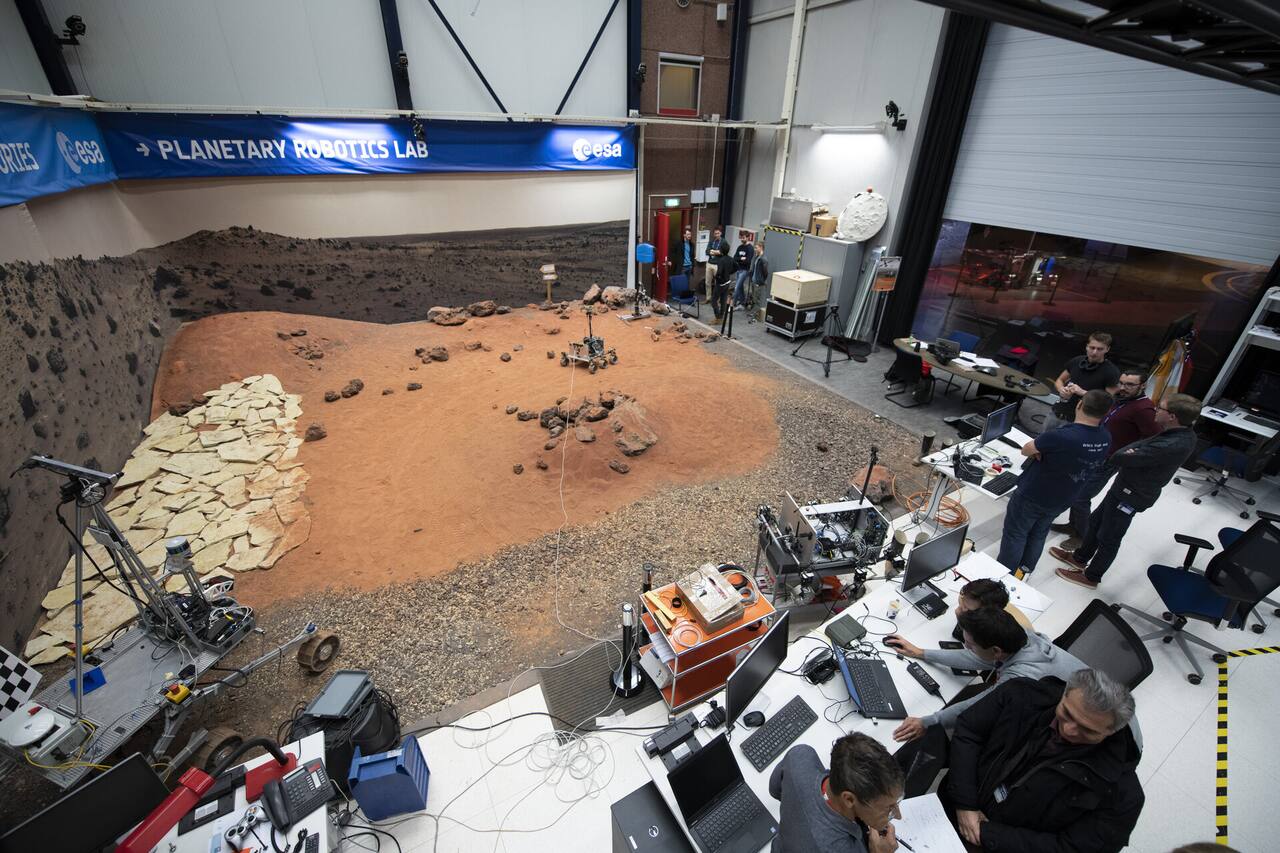
Section titled “Mars Yard”The Mars Analogue Terrain, called the Mars Yard as a nickname rather than as an official name, is the terrain bed of the Planetary Robotics Laboratory: sand, gravel and rock of several sizes laid out as a small crater, a boulder field, a sandy dune and a gravel slope area, in which small to mid-size rovers demonstrate locomotion and navigation [2].
| Parameter | Value |
|---|---|
| Working volume | 9 x 9 m bed; 8 x 8 m in ESA’s older description [2]. Bed depth not published |
| Temperature | Not controlled, ambient [1] |
| Illumination | Not published. No solar simulator described |
| Simulant or terrain | Sand, gravel and rock. No tonnage or grain size distribution published [1][2] |
| Slope | A gravel slope area in the bed. No adjustable rig, no angle range published [2] |
| Instrumentation | Infrared motion tracking cameras [2]; RIEGL LMS-Z210i terrain scans [1] |
ESA describes the bed as a sandbox filled with sand, gravel and rock of different sizes. Nothing is published about tonnage, grain size distribution, relative density target or how the bed is prepared between runs, so two campaigns in it are not comparable on soil state. The material is graded sand and rock rather than a mineralogically matched simulant, which is the deliberate consequence of what the bed is for [1].
Planetary Utilization Testbed is ESA’s older name for the same bed, carried on a legacy page that gives it as 8 by 8 m against the 9 by 9 m of the current description, with a flagstone slope section and infrared motion tracking for position ground truth [2]. It is the bed in which ExoTeR ran sample tube detection and autonomous navigation work.
ORBIT, the Orbital Robotics Bench for Integrated Technology, is a 45 m2 epoxy floor leveled to gravity to within 0.7 mm across its whole surface, on which platforms ride on air bearings [3]. Two translational and one rotational degree of freedom are relieved, which is the whole trade the operators state: planar microgravity is bought “at the cost of reducing the system to three DoF”. It is the free-floating half of the Orbital Robotics and GNC Laboratory, whose other half is the 33 m GRALS rail arm [4].
ESA. CC BY-SA IGO.
| Parameter | Value |
|---|---|
| Working volume | 45 m2 epoxy floor: 5 x 9 m in the operators’ papers, 9 x 4.8 m on ESA’s page [3] |
| Test article limits | 250 kg, the laboratory crane limit; floor loading 500 kg/m2 [3][4] |
| Slope | None; the floor is leveled to gravity, maximum slope below 0.3 mm/m [3] |
| Gravity offload | Air bearings, 3 DoF; flatness 0.7 mm, residual acceleration 1.5 mm/s2 |
| Instrumentation | Vicon Bonita B10 motion capture, sub-millimeter, to 250 Hz [3] |
The floor was built to a flatness specification rather than laid and then measured. Ground concrete was covered by rows of leveled concrete screed set to gravity with a Leica AT402 absolute laser tracker, the gaps were filled, and low-viscosity epoxy was applied in layers with sanding between them, with laser tracker verification at every step [3]. The result is 0.7 mm of maximum deviation over 45 m2, with no general trend to tilt in any direction, and a surface whose roughness, RA below 0.9 um, RQ below 0.6 um and RZ below 1.8 um, is one to two orders of magnitude below the air gap of a few tens of microns the bearings ride on. Because the floor is not on the ground floor of the building, building movement is a standing concern, and the flatness was re-measured six months after commissioning specifically to check for it; no apparent change was found. ESA restates the flatness as 0.7 plus or minus 0.1 mm with respect to gravity, a maximum height variation of 0.67 mm, a maximum slope below 0.3 mm/m and a residual natural acceleration of 1.5 mm/s2 [1].
Access to the floor is by a fold-away ramp from the laboratory’s raised computer floor. Three rows of 45 mm aluminum profile run along the walls at 55, 140 and 225 cm above the floor, each to plus or minus 1 cm, for mounting targets and mock-ups [3].
The platforms are the variable part. MANTIS, the Maneuverable Testbed for In-orbit Simulation, rides on three carbon air bearing pucks at 25.82 plus or minus 0.05 kg dry with a moment of inertia of 1.667 plus or minus 0.09 kg m2 and about 50 kg of payload capacity [3]. ACROBAT is the large platform at 128.85 plus or minus 0.05 kg and 8.154 plus or minus 0.09 kg m2, which with the SATSIM propulsion and RECAP stack reaches 221.67 kg, 12.223 kg m2, 102.5 cm tall and 35 cm in radius, and carries 4 kg of 300 bar breathing air [3][8]. ROOTLESS is the actively leveled platform, about 15 kg of payload, rebuilt on a Neobotix MPO-500 mobile base by 2018 [3][4]. ROMA carries a UR10e arm on a 35 kg platform with a 12.5 kg payload [1]. Platform masses across the set run 35 to 250 kg with payloads to 200 kg by default and more “with minimal engineering effort”. Platform actuation is eight 10 N air thrusters, eight air propellers to 6 N and a 4 kg reaction wheel, with about 30 minutes of autonomy on integrated tanks, plus an ejection mechanism giving representative delta-v and tumbling conditions [3].
ROOTLESS inverts the facility’s own design premise. Instead of demanding a perfectly level floor, it levels itself on three supports using a high-accuracy inclinometer and three precision linear stepper motors, and can then deliberately tilt its payload plate to introduce a controlled lateral force that emulates a chosen low gravity level [4][5][7]. The operators note that the approach “allows to have less stringent requirements on the floor flatness which makes testing cheaper”, which is a direct statement that extreme floor flatness is expensive to buy and to keep.
By 2018 the laboratory had been rebuilt and extended: the compressed air installation was changed for a new robotic gantry, 300 bar refilling was moved inside the flat floor area, the 33 m GRALS rail arm was added, and ROOTLESS was rebuilt on its mobile base [4]. GRALS carries satellite and terrain models and the illumination for vision-based navigation work, and is used together with the floor: GRALS flies the approach while ORBIT supplies the free-floating target and the contact dynamics [4][5][7].
Dusty Thermal Vacuum Chamber
Section titled “Dusty Thermal Vacuum Chamber”The Dusty Thermal Vacuum Chamber is the principal instrument of the Regolith Interaction Facility, a small thermal vacuum chamber with a simulant bed inside it, held between -150 and +125 C. Its published parameter list contains one number that most vacuum facilities do not publish at all: the base pressure with dust in the chamber, an order of magnitude worse than the base pressure clean [1].
| Parameter | Value |
|---|---|
| Working volume | Shroud 0.85 m diameter by 1 m high; regolith bed 0.5 x 0.5 x 0.2 m |
| Vacuum | 10^-5 mbar clean, about 7.5 x 10^-6 torr; 10^-4 to 10^-5 mbar with regolith present |
| Temperature | -150 to +125 C, liquid nitrogen; shroud and base plate controlled separately |
| Simulant or terrain | Bed fillable with different simulants; product, tonnage and density not published |
Source: [1].
The chamber is small by design and its geometry states what it is for. The shroud and the base plate sit on separately controlled liquid nitrogen circuits, so the soil and the surrounding radiative environment can be set to different temperatures. That separation is the feature: a lunar mechanism’s problem is usually a cold tool working into cold soil while some other part of it is warm, and a single-zone chamber cannot pose that [1].
The facility exists because regolith properties are difficult to model, and, in ESA’s words, “any equipment designed to operate in contact with regolith, requires early testing to confirm that the assumptions taken in the design phases hold against the difficulty to model regolith properties” [1]. ESA lists six application areas, and they define the article envelope more usefully than a mass limit would: wheel and soil interaction for mobility systems; regolith sampling, drilling, excavation and conveying for scientific sampling and in-situ resource utilization support; regolith beneficiation by size separation or mineral enrichment; dust and temperature effects on motors, drive mechanisms, cameras, lidars and force-torque sensors; sealing technologies for robotic joints; and deployment and pointing mechanism development for the lunar surface. Pumped volume, pump type, pumpdown time and cleanup burden between campaigns are not published.
Human Robot Interaction Laboratory
Section titled “Human Robot Interaction Laboratory”The fourth laboratory of the group shares its equipment with ORBIT: a human-rated floating chair carrying a VR headset, mounted on the same standard platform base as the attitude actuators and the manipulator stack [1]. No room dimensions or instrumentation are published.
Instrumentation
Section titled “Instrumentation”Position ground truth in the Mars Yard comes from infrared motion tracking cameras [2]. On the ORBIT floor the equivalent is a Vicon system: the 2016 facility paper’s abstract says fourteen cameras and its body text says twelve Vicon Bonita B10 cameras at up to 250 Hz, giving sub- millimeter real-time localization from at least four reflective markers per tracked body, while ESA’s current page states sub-millimeter accuracy without a camera count [3]. The value of tracking both a manipulator and the object it touches on one system is that the contact is measured independently of either body’s own state estimate. Terrain ground truth for rover experiments is generated by the RIEGL LMS-Z210i scanner, and calibration of sensor frames by the Nikon K600, at 0.1 mm position accuracy over a 4 by 2 by 2 m volume [1].
Mass properties on ORBIT are measured rather than modeled. A center of gravity rig places the platform on a 900 mm honeycomb plate over three load cells, good to 150 kg with 10 g weight accuracy and sub-millimeter center of gravity resolution; a moment of inertia rig suspends the platform on springs and measures the oscillation with a gyroscope, at 1 to 2 percent accuracy [3]. Both matter because a floating platform’s dynamics are set by properties that change every time a payload is bolted on, which is why the published platform figures carry their measurement uncertainties [3].
The air plant supports two distinct pressures. A Bauer Oceanus E dive compressor fills the platforms’ onboard bottles to 200 or 300 bar at 140 l/min; a separate Atlas Copco SF11 oil-free scroll compressor supplies 10 bar at 900 l/min across four outlets, two pressure-regulated to 8 bar and two flow-monitored, for tethered operation, alongside a nitrogen outlet [3].
In the Dusty Thermal Vacuum Chamber nothing is published. ESA’s facility panel lists the shroud dimensions, the bed dimensions, the two vacuum levels and the temperature range, and gives no instrument. A campaign there brings its own measurement, or the article under test is itself the instrument, which is consistent with the application list where cameras, lidars and force-torque sensors appear as objects of study rather than as facility equipment [3].
What it does not reproduce
Section titled “What it does not reproduce”Vacuum, thermal or reduced gravity in the terrain bed. The Mars Yard is an ambient-pressure, ambient-temperature, one-g bed whose published parameters cover terrain geometry, rover testbeds and metrology and nothing else [1]. Its material is sand, gravel and rock rather than a mineralogically matched simulant [2], so it supports locomotion, perception, navigation and arm placement work and not tribology, dust adhesion or electrostatics.
Vehicle scale, where dust and vacuum are available. The Dusty Thermal Vacuum Chamber’s shroud is 0.85 m in diameter by 1 m high and its bed is 0.5 by 0.5 by 0.2 m [1], which admits one wheel, one drill string or one end effector. Nothing traverses it.
Its own clean base pressure, once regolith is inside. The published figures are 10^-5 mbar clean and 10^-4 to 10^-5 mbar dusty [1]. Publishing both is unusual and useful: it states, as a facility parameter, that the environment a dusty test actually runs in is up to an order of magnitude coarser than the specification a clean test meets.
A documented soil state in the chamber. The bed “can be filled with different simulants” [1] and nothing is published about which, how much, how deep, how prepared or to what density. Two campaigns in that chamber are not comparable on the published record. There is also no published cleanup burden, simulant handling procedure or contamination policy. Illumination is absent as well, so the thermal environment is radiative from the shroud rather than solar, and the extreme surface gradients of a lunar terminator or a permanently shadowed region rim are not produced by a beam. Soil behavior in the bed is at 1 g overburden [1].
Three of the six degrees of freedom on ORBIT. The operators state the trade in the first paragraph of the facility paper: planar free floating is achieved “at the cost of reducing the system to three DoF” [3], and ESA’s own description repeats the qualification, that the facility is an analogue to microgravity “albeit constrained to a plane, simulating microgravity in two translational and one rotational dimension” [11].
Free drift for longer than a few seconds. This is the facility’s most useful published number. After a defined contact, the platform’s velocity vector deviates 10 percent from nominal after 4.9 s at a 30 mm/s approach, 6.9 s at 50 mm/s and 11.4 s at 100 mm/s, which the operators attribute to “local imperfections of the flatness of the floor on the sub-millimeter level”, noting that “while at higher velocities this effect is barely visible, it becomes more significant in lower velocity regimes or for longer durations” [3]. Slow approaches, which are the operationally realistic ones for rendezvous and capture, are the ones the floor corrupts fastest. Users concur that “the small slopes that exist on the floor are enough to introduce significant disturbances into the system” [8].
Closed-loop tracking to better than tens of centimeters. A university group flying an overactuated platform with eight thrusters and a reaction wheel reports 100 percent success in simulated trajectory finding and following but real-floor straight-line tracking only within tens of centimeters [9], and attributes the gap to floor unevenness: “given the large weight of the system and the comparably low force capabilities by the thrusters, high actuation is required to compensate even small disturbances induced by the unevenness of the flat-floor” [8].
One agreed number for the floor’s flatness. Three figures circulate. The operators’ laser tracker measurement is 0.7 mm maximum deviation over the whole surface [3]; ESA’s page gives a maximum slope below 0.3 mm/m and a residual acceleration of 1.5 mm/s2 [1]; and the simulation heightmap a user built from the operators’ data is characterized as “a maximal deviation of 1 mm over one meter” [9]. The first is a global bound and the others are local gradients, so they are not the same quantity and should not be substituted for each other.
Unlimited test duration on the floor. A run ends when the platform’s cold gas does, with about 30 minutes of autonomy on integrated tanks and less when thrusters are working hard [1][9].
Anything above 250 kg on the floor. Not because the floor cannot carry it, at 500 kg/m2, but because the crane that puts a platform on the floor lifts 250 kg [3][4].
Campaigns run there
Section titled “Campaigns run there”ExoMars autonomous navigation, 2018 to 2019. ExoTeR, the half-scale ExoMars testing rover, was driven in the 9 by 9 m terrain bed running CNES-developed autonomous navigation software, with the yard laid out in red sand, gravel and rock and instrumented for position ground truth [1]. The laboratory maintained ExoTeR as its primary testbed for about a decade before MaRTA was built to replace it [1]. See rosalind-franklin.
MaRTA force-torque sensor assessment, 2023 to 2024. MaRTA, carrying six force-torque sensors mounted above the wheels alongside an IMU, was driven over varying terrain, slopes and speeds in a field campaign at Bardenas Reales, Spain, producing the BASEPROD dataset [12]. The finding was negative and specific: drawbar pull could not be read from the above-wheel force-torque sensors in a meaningful way, the vibration superimposed on the signals made them harder to interpret than expected, and the authors recommend cheaper conventional sensors, or mounting in the drive hub and correlating with motor current, over the above-wheel configuration. They also record that confirming the candidate drawbar pull extraction needs experiments with external ground truth on defined slopes with known ground parameters, which a field campaign cannot supply [12]. For terrain classification the force-torque sensors did outperform the IMU [12].
BASEPROD dataset, July 2023. The underlying dataset covers 24 traverses of 6.85 m to 202 m, about 1.7 km and roughly 450 GB of logs, recorded between 20 and 23 July 2023 [13]. MaRTA carried an Xsens MTi-680 IMU with RTK GNSS receiver, a Realsense D435i tilted down 20 degrees, a Bumblebee XB3 on a mast pan and tilt unit with a 24 cm baseline, an Optris PI 640i thermal camera, a KVH DSP-1760 fiber optic gyro for yaw and six ATI mini45 force-torque sensors, one per wheel leg. A DJI Mavic 2 Pro produced a georeferenced photogrammetric map and a portable LIBS instrument sampled terrain composition along the routes [13].
ROSPA cross-validation against GMV platform-art, 2016. A Mitsubishi PA10 arm mounted on the ORBIT floor pushed a spherical probe with one degree of freedom of spring compliance into a cylinder carried by the MANTIS platform, at approach speeds of 30, 50 and 100 mm/s, with Vicon tracking both bodies [3]. What was measured was the post-contact free-drift velocity vector against a one degree of freedom contact model; what was found is the drift budget quoted above, which bounds how long after a contact the floor still represents free space [3].
Uncooperative rendezvous and capture, 2018. GRALS carried a vision-based navigation camera and the COSMIC gripper toward a Launch Adapter Ring target while ORBIT supplied the free-floating target and the contact dynamics at the moment of capture [4].
Landing with surface contact, 2018. GRALS flew the descent with camera and altimeter and forwarded the landing state vector and attitude to an ORBIT platform, which performed the landing force test [4].
ROOTLESS active leveling, 2018. Validation that a slight commanded tilt of the payload plate introduces a controlled lateral force, so that microgravity or a chosen lower gravity level can be emulated on a floor that is not perfectly level [5][6][7].
Overactuated platform trajectory control, 2022. The ACROBAT, SATSIM and RECAP stack with eight solenoid thrusters of about 10 N each and one reaction wheel, modeled in Gazebo against a digital elevation model of the floor [8][9]. Monte Carlo trajectory finding and following succeeded in every simulated case; on the real floor, straight line tracking held only to tens of centimeters, with the disturbance dominated by floor unevenness [8][9].
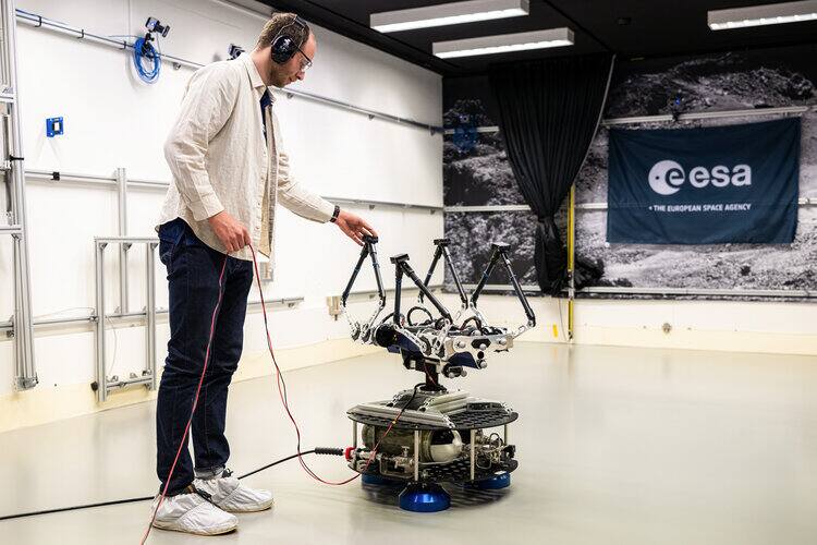
Olympus quadruped in-flight attitude control, 2026. The Norwegian University of Science and Technology’s Olympus, with motors limited to 12 Nm, mounted on a rotating rod over a floating platform, with motion capture supplying the state estimate [10]. Single-axis reorientation times were compared between simulation and hardware, and a 90 degree reorientation was achieved in 2.6 s on hardware [10]. This is the campaign shown in the ORBIT photograph above.
Docking and capture generally. The flat floor is used for close-range rendezvous, docking, berthing of free-floating objects and landing on low-gravity bodies, with an ejection mechanism providing representative delta-v and tumbling conditions, and the ROMA platform carrying a UR10e for docking interface and in-space servicing autonomy tests [1].
Where the facilities sit among comparable testbeds
Section titled “Where the facilities sit among comparable testbeds”The three ESTEC capabilities are one instance each of a design that other agencies and laboratories have also built, and the comparison shows which limits are specific to ESTEC and which are inherent to the approach.
Indoor terrain beds. The JPL Planetary Robotics Laboratory states 1500 sq ft (about 139 m2) of assembly floor and a further 1500 sq ft holding two indoor sand pits of loose, rocky soil, and publishes neither pit dimensions nor soil properties [16]. That is the same disclosure gap as the Mars Yard. The DLR Moon-Mars test site is outdoors, 1500 m2, with a 10 m wide, 2 m deep crater, 15 and 35 degree slopes, a 4 m concrete lava tube and a 16 by 2 m sand patch for drilling, and it publishes the chain from use case to requirement to terrain feature, which the ESTEC pages do not [17]. The KSC Surface Autonomy Test Site is 21.3 by 33.5 m, enclosed, with a granular bed and scattered rocks, and states no simulant or geotechnical data [29]. Of the held descriptions, the ESA European Astronaut Centre LUNA facility is the one paired with a measured material characterization: about 20 tons of EAC-1 mare simulant over 750 m2, 60 cm deep, with abrasivity rated on the Soil Abrasion Test scale, where EAC-1 is 6.5 and Lumina2000 is the most abrasive [15]. That characterization covers 5 kg laboratory samples, not the beds in use [15]. All of these beds are ground facilities; none is a flown system.
Dusty vacuum and combined environments. The DTVAC bed is small because soil under vacuum is hard to hold. At NASA Glenn the largest simulant bed put under vacuum to that date, 1 m2 by 0.6 m deep and roughly 900 kg, was disturbed by interstitial gas escaping during pumpdown, and the controlling variable was pressure decay rate rather than absolute pressure; no disruption was seen below 2.5 Torr [21]. DTVAC publishes a clean and a dusty base pressure but no pumpdown procedure, so the same effect cannot be assessed for it. The Glenn Lunar Dust Adhesion Bell Jar requirements document sets out five factors a lunar simulation must reproduce (dust, vacuum, temperature, solar radiation, reduced gravity) and a dust activation protocol of bakeout at 200 C and three thermal cycles to about -150 C, because simulant from the bottle is not lunar dust [23]. DTVAC has no published equivalent. The Marshall PLANET chamber, 2 by 3 m with a 1.22 by 2.44 m bed holding about 800 kg, adds plasma and ultraviolet sources, and its designers size it by the 0.2 to 0.5 m spot over which those sources stay uniform; it was a design intent, not a measured facility, when published [22]. A thermal vacuum environment on the other side of the ESTEC site is the Large Space Simulator, 15 m high by 10 m wide, which serves spacecraft thermal balance and deployment rather than regolith work [24].
Reduced gravity for rovers. Neither the terrain bed nor DTVAC offloads weight. Parabolic flights on a Falcon 20 found that matching only wheel load (reduced-weight testing) overstates mobility: drawbar pull to weight fell 20 percent or more and sinkage rose by up to 40 percent at equal load in lunar gravity [28]. Each parabola gives 20 to 30 seconds, so the data are transient [28]. An ESTEC rover run at 1 g is therefore a statement about a heavier vehicle, which is a limit the published pages do not state.
Offload and air-bearing alternatives. Constant-force pneumatic offload held a commanded partial-gravity force to within 2.2 to 10 percent across 16 subject, gravity and speed combinations in a 1994 JSC test, with error rising as the motion became faster [18]. Cable suspension at the NASA ARGOS rig depends on gimbal pivot placement: functional settings fell about 2.5 to 6.4 cm above and 1.3 to 2.5 cm aft of the modeled center of gravity, and a 0.6 cm fore and aft shift was perceptible [19]. The DLR Landing and Mobility Test Facility suspends test articles from a 500 kg robot on a 12 m rail, and in the Philae touchdown tests a rig artifact appeared directly in the data as a high negative acceleration peak [20]. These approaches buy the out-of-plane degrees of freedom that ORBIT gives up, and they introduce their own artifacts; none removes the need to characterize the rig. In orbit, the free flyers that ground floors prepare for have flown: Astrobee has accumulated more than 165 real time operations and more than 90 Guest Science sessions on the ISS, with impeller propulsion replacing cold gas [26]. The SPHERES cold gas thruster measured 0.1783 N at 55 psig against 0.2480 N predicted, and thrust was not independent between thrusters [27]. Both illustrate the gap between a bench or floor model and the flown actuator.
Servicing and capture validation. A survey of space manipulation and capture treats ground testbeds as one stage between simulation and the flown demonstrations ETS-VII, Orbital Express and Aolong-1 [25]. The Orbital Express video guidance sensor ground test compared ten ground static cases with fifteen mated flight cases, and standard deviations stayed below 0.005 degrees against a 0.033 degree specification, but only in static, near-docked geometry from 1.2 to 3 m [32]. That is the evidence class a flat-floor campaign aims for and rarely reaches.
System testbed fidelity. The JPL Mars 2020 testbed team ranks venues on hardware fidelity, avionics fidelity and a third axis, without units or scores, and uses it to decide where a verification item can be closed [30]. A scaled treadmill vehicle testbed validated against full-size cars by Buckingham Pi matching of dynamic parameters shows a method for stating what a scaled facility represents [31]. Neither is a space facility; both are the missing step for the ESTEC beds, whose rovers are half-scale and whose platforms are not identified.
What is not established
Section titled “What is not established”The published record for these laboratories is largely ESA’s own facility pages and the operators’ papers, and the pages state no soil identity, grain size distribution, bearing strength, slope angles or motion tracking accuracy for the terrain bed [2]. The two ESA descriptions of the bed disagree on its size, 8 by 8 m against 9 by 9 m, and on the ORBIT floor, 4.8 by 9 m against 5 by 9 m in the papers [2][3][11]. The ORBIT page gives no residual acceleration, platform mass limit or run duration, so the fidelity of the planar emulation is judged from the operators’ paper [3][11]. The one sim-to-real comparison available covers one region of one floor, one straight-line and one semicircular trajectory with no repeats, and an unidentified platform model, so its error ratio should not be transferred to another flat floor [9]. The Dusty Thermal Vacuum Chamber has no published campaign results in the held sources, and its simulant, density and cleanup procedure are unstated [1].
References
- (2026). ESA Automation and Robotics Laboratories. technology.esa.int/lab/automation-and-robotics-laboratories
BibTeX
@misc{esaarlabs, title = {ESA Automation and Robotics Laboratories}, organization = {technology.esa.int}, year = {2026}, url = {https://technology.esa.int/lab/automation-and-robotics-laboratories} } - (2026). ESA: Mars on Earth. esa.int/Enabling_Support/Space_Engineering_Technology/Mars_on_Earth
BibTeX
@misc{esamarsonearth, title = {ESA: Mars on Earth}, organization = {esa.int}, year = {2026}, url = {https://www.esa.int/Enabling_Support/Space_Engineering_Technology/Mars_on_Earth} } - Kolvenbach, H. and Wormnes, K. (2016). Recent Developments on ORBIT, a 3-DoF Free Floating Contact Dynamics Testbed
. International Symposium on Artificial Intelligence, Robotics and Automation in Space. Source
BibTeX
@inproceedings{kolvenbach2016recent, title = {Recent Developments on {ORBIT}, a 3-{DoF} Free Floating Contact Dynamics Testbed}, author = {Kolvenbach, Hendrik and Wormnes, Kjetil}, booktitle = {International Symposium on Artificial Intelligence, Robotics and Automation in Space}, organization = {European Space Agency}, address = {Beijing, China}, year = {2016}, url = {https://roboshare.esa.int/i-SAIRAS/isairas2016/Session2c/S-2c-2-HendrikKolvenbach.pdf} } - Zwick, M., Huertas, I., Gerdes, L. and Ortega, G. (2018). ORGL: ESA's Test Facility for Approach and Contact Operations in Orbital and Planetary Environments
. International Symposium on Artificial Intelligence, Robotics and Automation in Space. Source
BibTeX
@inproceedings{zwick2018orgl, title = {{ORGL}: {ESA}'s Test Facility for Approach and Contact Operations in Orbital and Planetary Environments}, author = {Zwick, Martin and Huertas, Irene and Gerdes, Levin and Ortega, Guillermo}, booktitle = {International Symposium on Artificial Intelligence, Robotics and Automation in Space}, organization = {European Space Agency}, address = {Madrid, Spain}, year = {2018}, url = {https://roboshare.esa.int/i-SAIRAS/isairas2018/} } - Velosa, C. M. N., Gerdes, L. and Zwick, M. (2018). Automatic Levelling of a Platform to Achieve Artificial Gravity
. International Symposium on Artificial Intelligence, Robotics and Automation in Space. Source
BibTeX
@inproceedings{velosa2018automatic, title = {Automatic Levelling of a Platform to Achieve Artificial Gravity}, author = {Velosa, Carlos M. N. and Gerdes, Levin and Zwick, Martin}, booktitle = {International Symposium on Artificial Intelligence, Robotics and Automation in Space}, organization = {European Space Agency}, address = {Madrid, Spain}, year = {2018}, url = {https://roboshare.esa.int/i-SAIRAS/isairas2018/} } - Velosa, C. M. N., Gerdes, L. and Zwick, M. (2018). Optimal Control of a 3-DOF Free Floating Platform on a Flat Floor
. International Symposium on Artificial Intelligence, Robotics and Automation in Space. Source
BibTeX
@inproceedings{velosa2018optimal, title = {Optimal Control of a 3-{DOF} Free Floating Platform on a Flat Floor}, author = {Velosa, Carlos M. N. and Gerdes, Levin and Zwick, Martin}, booktitle = {International Symposium on Artificial Intelligence, Robotics and Automation in Space}, organization = {European Space Agency}, address = {Madrid, Spain}, year = {2018}, url = {https://roboshare.esa.int/i-SAIRAS/isairas2018/} } - Tomasek, J., Kolvenbach, H., Pagnamenta, M. and Wormnes, K. (2016). A Robotic Testbed for Low-Gravity Simulation
. International Symposium on Artificial Intelligence, Robotics and Automation in Space. Source
BibTeX
@inproceedings{tomasek2016robotic, title = {A Robotic Testbed for Low-Gravity Simulation}, author = {Tomasek, Jakub and Kolvenbach, Hendrik and Pagnamenta, Marco and Wormnes, Kjetil}, booktitle = {International Symposium on Artificial Intelligence, Robotics and Automation in Space}, organization = {European Space Agency}, address = {Beijing, China}, year = {2016}, url = {https://roboshare.esa.int/i-SAIRAS/isairas2016/Session3b/S-3b-4-HendrikKolvenbach.pdf} } - Bredenbeck, A., Vyas, S., Suter, W., Zwick, M., Borrmann, D., Olivares-Mendez, M. and Nüchter, A. (2022). Finding and Following Optimal Trajectories for an Overactuated Floating Robotic Platform
. arXiv preprint. Source
BibTeX
@article{bredenbeck2022finding, title = {Finding and Following Optimal Trajectories for an Overactuated Floating Robotic Platform}, author = {Bredenbeck, Anton and Vyas, Shubham and Suter, Willem and Zwick, Martin and Borrmann, Dorit and Olivares-Mendez, Miguel and Nüchter, Andreas}, journal = {arXiv preprint}, booktitle = {Symposium on Advanced Space Technologies in Robotics and Automation}, year = {2022}, doi = {10.48550/arxiv.2206.03993}, abstract = {The recent increase in yearly spacecraft launches and the high number of planned launches have raised questions about maintaining accessibility to space for all interested parties. A key to sustaining the future of space-flight is the ability to service malfunctioning - and actively remove dysfunctional spacecraft from orbit. Robotic platforms that autonomously perform these tasks are a topic of ongoing research and thus must undergo thorough testing before launch. For representative system-level testing, the European Space Agency (ESA) uses, among other things, the Orbital Robotics and GNC Lab (ORGL), a flat-floor facility where air-bearing based platforms exhibit free-floating behavior in three Degrees of Freedom (DoF). This work introduces a representative simulation of a free-floating platform in the testing environment and a software framework for controller development. Finally, this work proposes a controller within that framework for finding and following optimal trajectories between arbitrary states, which is evaluated in simulation and reality.} } - Bredenbeck, A., Vyas, S., Zwick, M., Borrmann, D., Olivares-Mendez, M. and Nüchter, A. (2022). Trajectory Optimization and Following for a Three Degrees of Freedom Overactuated Floating Platform
. IEEE/RSJ International Conference on Intelligent Robots and Systems. Source
BibTeX
@inproceedings{bredenbeck2022trajectory, title = {Trajectory Optimization and Following for a Three Degrees of Freedom Overactuated Floating Platform}, author = {Bredenbeck, Anton and Vyas, Shubham and Zwick, Martin and Borrmann, Dorit and Olivares-Mendez, Miguel and Nüchter, Andreas}, booktitle = {IEEE/RSJ International Conference on Intelligent Robots and Systems}, volume = {2}, pages = {4084-4091}, year = {2022}, doi = {10.1109/iros47612.2022.9981294}, abstract = {Space robotics applications, such as Active Space Debris Removal (ASDR), require representative testing before launch. A commonly used approach to emulate the microgravity environment in space is air-bearing based platforms on flat-floors, such as the European Space Agency's Orbital Robotics and GNC Lab (ORGL). This work proposes a control architecture for a floating platform at the ORGL, equipped with eight solenoid-valve-based thrusters and one reaction wheel. The control architecture consists of two main components: a trajectory planner that finds optimal trajectories connecting two states and a trajectory follower that follows any physically feasible trajectory. The controller is first evaluated within an introduced simulation, achieving a 100% success rate at finding and following trajectories to the origin within a Monte-Carlo test. Individual trajectories are also successfully followed by the physical system. In this work, we showcase the ability of the controller to reject disturbances and follow a straight-line trajectory within tens of centimeters.} } - Olsen, J. A. and Alexis, K. (2026). Towards Low-Gravity Planetary Exploration using Reinforcement Learning for Walking, Jumping, and In-flight Attitude Control
. arXiv. Source
BibTeX
@article{olsen2026towards, title = {Towards Low-Gravity Planetary Exploration using Reinforcement Learning for Walking, Jumping, and In-flight Attitude Control}, author = {Olsen, Jørgen Anker and Alexis, Kostas}, journal = {arXiv}, organization = {Autonomous Robots Lab, Norwegian University of Science and Technology}, year = {2026}, doi = {10.48550/arxiv.2605.24643}, abstract = {This paper presents reinforcement learning (RL) policies for dynamic quadrupedal locomotion in planetary exploration scenarios. Building on a taskoptimized quadruped with a 5-bar leg design, we develop RL policies for walking, vertical jumping, forward jumping, and in-flight attitude control, explicitly tailored to the reduced gravity on Mars. These policies jointly enable such robots to overcome obstacles larger than themselves through coordinated jumping and precise in-flight reorientation for safe landings. We demonstrate Sim2Real transfer of the attitude control policy on the Olympus quadruped through single-axis reorientation tests, while all locomotion policies are validated in simulation. A complete Mars exploration mission scenario demonstrates coordinated policy deployment across challenging terrain. Experimental results show 90° attitude reorientation in 2.6 seconds, with simulations demonstrating 3.1 meter vertical jumps and 3.9 meter forward jumps under Martian gravity conditions. - Supplementary video: https://www.youtube.com/watch?v=qlSJ3P87A4A} } - (2026). ESA: Orbital Robotics Laboratory. esa.int/Education/ESA_Academy_Experiments_programme/Orbital_Robotics_Lab
BibTeX
@misc{esaorbitallab, title = {ESA: Orbital Robotics Laboratory}, organization = {esa.int}, year = {2026}, url = {https://www.esa.int/Education/ESA_Academy_Experiments_programme/Orbital_Robotics_Lab} } - Gerdes, L., Pérez del Pulgar, C., Castilla Arquillo, R. and Azkarate, M. (2025). Field Assessment of Force Torque Sensors for Planetary Rover Navigation
. Journal of Intelligent and Robotic Systems. Source
BibTeX
@article{gerdes2025field, title = {Field Assessment of Force Torque Sensors for Planetary Rover Navigation}, author = {Gerdes, Levin and Pérez del Pulgar, Carlos and Castilla Arquillo, Raúl and Azkarate, Martin}, journal = {Journal of Intelligent and Robotic Systems}, volume = {111}, year = {2025}, doi = {10.1007/s10846-025-02324-2}, abstract = {Abstract Proprioceptive sensors on planetary rovers serve for state estimation and for understanding terrain and locomotion performance. While inertial measurement units (IMUs) are widely used to this effect, force-torque sensors are less explored for planetary navigation despite their potential to directly measure interaction forces and provide insights into traction performance. This paper presents an evaluation of the performance and use cases of force-torque sensors based on data collected from a six-wheeled rover during tests over varying terrains, speeds, and slopes. We discuss challenges, such as sensor signal reliability and terrain response accuracy, and identify opportunities regarding the use of these sensors. The data is openly accessible and includes force-torque measurements from each of the six-wheel assemblies as well as IMU data from within the rover chassis. This paper aims to inform the design of future studies and rover upgrades, particularly in sensor integration and control algorithms, to improve navigation capabilities.} } - Gerdes, L., Wiese, T., Castilla Arquillo, R., Bielenberg, L., Azkarate, M., Leblond, H., Wilting, F., Ortega Cortés, J., Bernal, A., Palanco, S. and Pérez del Pulgar, C. (2024). BASEPROD: The Bardenas Semi-Desert Planetary Rover Dataset
. Scientific Data. Source
BibTeX
@article{gerdes2024baseprod, title = {BASEPROD: The Bardenas Semi-Desert Planetary Rover Dataset}, author = {Gerdes, Levin and Wiese, Tim and Castilla Arquillo, Raúl and Bielenberg, Lars and Azkarate, Martin and Leblond, Hugo and Wilting, Falk and Ortega Cortés, Javier and Bernal, Adrián and Palanco, Santiago and Pérez del Pulgar, Carlos}, journal = {Scientific Data}, volume = {11}, pages = {1054}, year = {2024}, doi = {10.1038/s41597-024-03881-1}, abstract = {Abstract Dataset acquisitions devised specifically for robotic planetary exploration are key for the advancement, evaluation, and validation of novel perception, localization, and navigation methods in representative environments. Originating in the Bardenas semi-desert in July 2023, the data presented in this Data Descriptor is primarily aimed at Martian exploration and contains relevant rover sensor data from approximately 1.7km of traverses, a high-resolution 3D map of the test area, laser-induced breakdown spectroscopy recordings of rock samples along the rover path, as well as local weather data. In addition to optical cameras and inertial sensors, the rover features a thermal camera and six force-torque sensors. This setup enables, for example, the study of future localization, mapping, and navigation techniques in unstructured terrains for improved Guidance, Navigation, and Control (GNC). The main features of this dataset are the combination of scientific and engineering instrument data, as well as the inclusion of the thermal camera and force-torque sensors in particular.} } - (2026). ESA: Test Centre. technology.esa.int/lab/test-centre
BibTeX
@misc{esatestcentre, title = {ESA: Test Centre}, organization = {technology.esa.int}, year = {2026}, url = {https://technology.esa.int/lab/test-centre} } - Zemeny, A., Sardisco, L., Quinteros, S., Mikesell, T. D., Pirrie, D., Rose, L., Cowley, A. and Manick, K. (2024). The LUNA Analog Facility testbeds (ESA, EAC): contemporary characterization work of highland and mare lunar regolith simulants
. Frontiers in Space Technologies. Source
BibTeX
@article{zemeny2024luna, title = {The {LUNA} Analog Facility testbeds ({ESA}, {EAC}): contemporary characterization work of highland and mare lunar regolith simulants}, author = {Zemeny, Aliz and Sardisco, Lorenzo and Quinteros, Susana and Mikesell, T. Dylan and Pirrie, Duncan and Rose, Laura and Cowley, Aidan and Manick, Kaushik}, journal = {Frontiers in Space Technologies}, volume = {5}, pages = {1510635}, year = {2024}, doi = {10.3389/frspt.2024.1510635}, abstract = {The Luna Analog Facility, a joint ESA-DLR endeavour, consists of three components and spans an area of 1,000 m 2 , providing testbeds of simulated lunar environments. The main sections within the facility are a large area filled with lunar mare regolith simulant resembling mare regions and a smaller, individual “Dust Chamber”. The latter replicates highland conditions and contains approximately 20 tons of material, specifically simulating the fine-particle lunar regolith portion up to 250 µm. The Dust Chamber serves as a platform for testing various technologies, such as mechanical tools, robotic operations, in-situ resource utilization activities, and astronaut attire, as well as different procedures including rover and astronaut tasks. This work represents the geotechnical, geochemical and mineralogical characterization of the Lumina Sustainable Materials Ltd. 2023 batch highland simulants, from which Lunar250 is intended for use in the Luna Dust Chamber. Additionally, this work provides new results for ESA’s mare simulant, EAC-1. We provide data on particle size distribution, particle shape, abrasivity, density, water content, major and trace element geochemistry and modal mineralogy. As the simulants in the Luna Facility will be constantly overseen, this work organized by the Vulcan Facility (ESA) intends to support the monitoring of the geotechnical property variations of the simulants over time. Ultimately, we analysed several properties with different tools to emphasize how different methods and instruments affect the variability and reliability of the results.} } - NASA Jet Propulsion Laboratory. (2026). The Planetary Robotics Laboratory. robotics.jpl.nasa.gov/how-we-do-it/facilities/the-planetary-robotics-...
BibTeX
@misc{jplprl, title = {The Planetary Robotics Laboratory}, author = {{NASA Jet Propulsion Laboratory}}, organization = {robotics.jpl.nasa.gov}, year = {2026}, url = {https://robotics.jpl.nasa.gov/how-we-do-it/facilities/the-planetary-robotics-laboratory/} } - Görner, M., Cebulsky, J., Dömel, A., Durner, M., Giubilato, R., Kuhne, M., Müller, M. G., Lakatos, K., Lehner, P., Lichtenheldt, R., Rebele, B., Roser, M., Sakagami, R., Scheeler, Y., Schuster, M. J., Schütt, M., Stürzl, W., Vayugundla, M. and Wedler, A. (2024). The DLR Moon-Mars Test Site for Robotic Planetary Exploration
. International Conference on Space Robotics. Source
BibTeX
@inproceedings{goerner2024dlr, title = {The DLR Moon-Mars Test Site for Robotic Planetary Exploration}, author = {Görner, Martin and Cebulsky, Jennifer and Dömel, Andreas and Durner, Maximilian and Giubilato, Riccardo and Kuhne, Moritz and Müller, Marcus G. and Lakatos, Kristin and Lehner, Peter and Lichtenheldt, Roy and Rebele, Bernhard and Roser, Mattias and Sakagami, Ryo and Scheeler, Yunis and Schuster, Martin J. and Schütt, Manuel and Stürzl, Wolfgang and Vayugundla, Mallikarjuna and Wedler, Armin}, booktitle = {International Conference on Space Robotics}, pages = {245-252}, institution = {DLR Institute of Robotics and Mechatronics}, year = {2024}, doi = {10.1109/isparo60631.2024.10687411}, abstract = {Building robots for planetary exploration missions requires intensive testing throughout all phases of the design process. Especially, during hard- and software development as well as mission training the process benefits of easy-to-access test sites that offer realistic conditions. For this purpose we have built the 1500 m2DLR Moon-Mars test site in Oberpfaffenhofen, Germany. The facility provides a large variety of geological formations and ground substrates on a compact terrain as well as a rich set of power and network connections. As a unique feature of the outdoor test site, we prepared a dedicated link to the German Space Operations Center that enables telerobotic experiments from ISS. Furthermore, we provide an optical tracking system for ground truth measurement and control. We describe the design and construction process of the test site and present an overview of its features. Three experiments with our robots LRU1, LRU2 and the Scout rover regarding autonomous navigation and mapping, autonomous manipulation and sampling as well as advanced mobility tests demonstrate the usage of the test site.} } - Ray, D. M. (1994). Partial Gravity Simulation Using a Pneumatic Actuator with Closed Loop Mechanical Amplification
. NASA Lyndon B. Johnson Space Center, NASA TM-104798. Source
BibTeX
@techreport{ray1994partial, title = {Partial Gravity Simulation Using a Pneumatic Actuator with Closed Loop Mechanical Amplification}, author = {Ray, David M.}, number = {NASA TM-104798}, institution = {NASA Lyndon B. Johnson Space Center}, month = {June}, year = {1994}, url = {https://ntrs.nasa.gov/citations/19940029889}, abstract = {To support future manned missions to the surface of the Moon and Mars or missions requiring manipulation of payloads and locomotion in space, a training device is required to simulate the conditions of both partial and microgravity as compared to the gravity on Earth. The focus of this paper is to present the development, construction, and testing of a partial gravity simulator which uses a pneumatic actuator with closed loop mechanical amplification. Results of the testing show that this type of simulator maintains a constant partial gravity simulation with a variation of the simulated body force between 2.2 percent and 10 percent, depending on the type of locomotion inputs. The data collected using the simulator show that mean stride frequencies at running speeds at lunar and Martian gravity levels are 12 percent less than those at Earth gravity. The data also show that foot/ground reaction forces at lunar and Martian gravity are, respectively, 62 percent and 51 percent less than those on Earth.} } - Jarvis, S. L., Vu, L. Q., Gupta, G., Benson, E., Kim, K. H., Rhodes, R. and Rajulu, S. L. (2023). Development of ARGOS (Active Response Gravity Offload System) Offloading Assessments and Methodology for Lunar EVA Simulations
. International Conference on Environmental Systems, 20230002430. Source
BibTeX
@inproceedings{jarvis2023development, title = {Development of ARGOS (Active Response Gravity Offload System) Offloading Assessments and Methodology for Lunar EVA Simulations}, author = {Jarvis, Sarah L. and Vu, Linh Q. and Gupta, Garima and Benson, Elizabeth and Kim, K. Han and Rhodes, Richard and Rajulu, Sudhakar L.}, booktitle = {International Conference on Environmental Systems}, number = {20230002430}, institution = {NASA}, address = {Calgary}, year = {2023}, url = {https://ntrs.nasa.gov/citations/20230002430}, abstract = {The Active Response Gravity Offload System (ARGOS) at NASA Johnson Space Center (JSC) is an analog environment that can offload pressurized suited subjects for various reduced gravity simulations. The suit is suspended from a robotic overhead crane by a cable connected to the suit via a gimbal with an adjustable pivot point (i.e. offload attachment). There has been increased interest in providing planetary pressurized suited training at ARGOS in preparation for lunar missions. Determination of the appropriate gimbal pivot point location for a given subject is vital for a high-fidelity functional lunar simulation. Interactions between the pivot point location and human-spacesuit center of gravity (CG) can result in righting moments that may lead to artificially stable or unrealistically challenging configurations. Changing the pivot point location is time consuming and repeated adjustment can result in loss of valuable pressurized suited time. This paper aims to share knowledge obtained from the offloading characterization efforts during pressurized suited testing at ARGOS and document the ongoing process to define an appropriate pivot point location through iterative quantitative and qualitative assessments. Human-spacesuit CG locations for the ARGOS lunar simulation were estimated using a 3D body scan and density model combined with spacesuit hardware CAD and specifications. Early pilot testing of the gimbal revealed that setting the pivot point coincident with the modeled CG location was not always possible due to the current gimbal design, and small pivot point shifts had noticeable effects on subject stability. Fourteen subjects performed a series of CG-related tasks in the Exploration Extravehicular Mobility Unit (xEMU) to assess simulation characteristics. Through iterative testing, this task list evolved to streamline the process needed to efficiently identify a suitable pivot point for a given subject. The developed methodology will be critical for pivot point selection during astronaut training in the ARGOS environment.} } - Schröder, S., Biele, J., Block, J., Roll, R., Ulamec, S. and Witte, L. (2013). Philae Landing Test at the Landing and Mobility Test Facility (LAMA)
. International Astronautical Congress, IAC-13, A3, 4, 3. Source
BibTeX
@inproceedings{schroder2013philae, title = {Philae Landing Test at the Landing and Mobility Test Facility (LAMA)}, author = {Schröder, Silvio and Biele, Jens and Block, Joachim and Roll, Reinhard and Ulamec, Stephan and Witte, Lars}, booktitle = {International Astronautical Congress, IAC-13, A3, 4, 3}, address = {Beijing}, year = {2013}, url = {https://elib.dlr.de/103154/} } - Kleinhenz, J. E. and Wilkinson, R. A. (2014). Development and Testing of an ISRU Soil Mechanics Vacuum Test Facility
. NASA Glenn Research Center, NASA/TM-2014-218389. Source
BibTeX
@techreport{kleinhenz2014development, title = {Development and Testing of an ISRU Soil Mechanics Vacuum Test Facility}, author = {Kleinhenz, Julie E. and Wilkinson, R. Allen}, number = {NASA/TM-2014-218389}, institution = {NASA Glenn Research Center}, year = {2014}, url = {https://ntrs.nasa.gov/citations/20150000323}, abstract = {For extraterrestrial missions, earth based testing in relevant environments is key to successful hardware development. This is true for both early component level development and system level integration. For In-Situ Resource Utilization (ISRU) on the moon, hardware must interface with the surface material, or regolith, in a vacuum environment. A relevant test environment will therefore involve a vacuum chamber with a controlled, properly conditioned bed of lunar regolith simulant. However, in earth-based granular media, such as lunar regolith simulant, gases trapped within the material pore structures and water adsorbed to all particle surfaces will release when exposed to vacuum. Early vacuum testing has shown that this gas release can occur violently, which loosens and weakens the simulant, altering the consolidation state. A mid-size chamber (3.66 m tall, 1.5 m inner diameter) at the NASA Glenn Research Center has been modified to create a soil mechanics test facility. A 0.64 m deep by 0.914 m square metric ton bed of lunar simulant was placed under vacuum using a variety of pumping techniques. Both GRC-3 and LHT-3M simulant types were used. Data obtained from an electric cone penetrometer can be used to determine strength properties at vacuum including: cohesion, friction angle, bulk density and shear modulus. Simulant disruptions, caused by off-gassing, affected the strength properties, but could be mitigated by reducing pump rate. No disruptions were observed at pressures below 2.5 Torr, regardless of the pump rate. The slow off-gassing of the soil at low pressure lead to long test times; a full week to reach 10(exp -5) Torr. Robotic soil manipulation would enable multiple ISRU hardware test within the same vacuum cycle. The feasibility of a robotically controlled auger and tamper was explored at vacuum conditions.} } - Hayward, E. G., Nehls, M. K., Schneider, T. A., Lynn, P., Bertone, P. F. and Vaughn, J. A. (2023). Designing the PLANET Chamber for Lunar Environment Ground Testing
. AIAA SCITECH Forum, 20220018888. Source
BibTeX
@inproceedings{hayward2023designing, title = {Designing the PLANET Chamber for Lunar Environment Ground Testing}, author = {Hayward, Erin G. and Nehls, Mary K. and Schneider, Todd A. and Lynn, Patrick and Bertone, Peter F. and Vaughn, Jason A.}, booktitle = {AIAA SCITECH Forum}, number = {20220018888}, address = {National Harbor, Maryland}, year = {2023}, doi = {10.2514/6.2023-2468}, abstract = {View Video Presentation: https://doi.org/10.2514/6.2023-2468.vid The Planetary, Lunar, and Asteroid Natural Environments Testbed (PLANET) is a new 2m x 3m high-vacuum chamber facility currently being designed and built at NASA’s Marshall Space Flight Center. When completed, it will be one of the highest-fidelity space/surface environment simulation chambers in existence. Instrumented with equipment to produce charged particle radiation, full spectrum ultraviolet, low-density plasma, and thermal extremes, PLANET can be configured to recreate the most challenging space environments. Additionally, a large regolith bed and distribution system will expose hardware to lunar regolith simulants and dust. This paper will describe the process of designing and optimizing PLANET and discuss some common considerations for performing ground-based environmental testing for lunar exploration.} } - Gaier, J. R. and Sechkar, E. A. (2007). Lunar Simulation in the Lunar Dust Adhesion Bell Jar
. AIAA Aerospace Sciences Meeting, NASA/TM-2007-214704. Source
BibTeX
@inproceedings{gaier2007lunar, title = {Lunar Simulation in the Lunar Dust Adhesion Bell Jar}, author = {Gaier, James R. and Sechkar, Edward A.}, booktitle = {AIAA Aerospace Sciences Meeting}, number = {NASA/TM-2007-214704}, institution = {NASA}, year = {2007}, doi = {10.2514/6.2007-963}, abstract = {The Lunar Dust Adhesion Bell Jar has been assembled at the NASA Glenn Research Center to provide a high fidelity lunar simulation facility to test the interactions of lunar dust and lunar dust simulant with candidate aerospace materials and coatings. It has a sophisticated design which enables it to treat dust in a way that will remove adsorbed gases and create a chemically reactive surface. It can simulate the vacuum, thermal, and radiation environments of the Moon, including proximate areas of illuminated heat and extremely cold shadow. It is expected to be a valuable tool in the development of dust repellant and cleaning technologies for lunar surface systems.} } - (2026). ESA: Large Space Simulator (LSS). esa.int/Enabling_Support/Space_Engineering_Technology/Test_centre/Lar...
BibTeX
@misc{esalssoverview, title = {ESA: Large Space Simulator (LSS)}, organization = {esa.int}, year = {2026}, url = {https://www.esa.int/Enabling_Support/Space_Engineering_Technology/Test_centre/Large_Space_Simulator_LSS} } - Papadopoulos, E., Aghili, F., Ma, O. and Lampariello, R. (2021). Robotic Manipulation and Capture in Space: A Survey
. Frontiers in Robotics and AI. Source
BibTeX
@article{papadopoulos2021robotic, title = {Robotic Manipulation and Capture in Space: A Survey}, author = {Papadopoulos, Evangelos and Aghili, Farhad and Ma, Ou and Lampariello, Roberto}, journal = {Frontiers in Robotics and AI}, volume = {8}, pages = {686723}, year = {2021}, doi = {10.3389/frobt.2021.686723}, abstract = {Space exploration and exploitation depend on the development of on-orbit robotic capabilities for tasks such as servicing of satellites, removing of orbital debris, or construction and maintenance of orbital assets. Manipulation and capture of objects on-orbit are key enablers for these capabilities. This survey addresses fundamental aspects of manipulation and capture, such as the dynamics of space manipulator systems (SMS), i.e., satellites equipped with manipulators, the contact dynamics between manipulator grippers/payloads and targets, and the methods for identifying properties of SMSs and their targets. Also, it presents recent work of sensing pose and system states, of motion planning for capturing a target, and of feedback control methods for SMS during motion or interaction tasks. Finally, the paper reviews major ground testing testbeds for capture operations, and several notable missions and technologies developed for capture of targets on-orbit.} } - Alexandrov, O., Barlow, J., Benavides, J., Bualat, M., Carlino, R., Coltin, B., Cortez, J., Daley, E., Feller, J., Flückiger, L., Fong, T., Fusco, J., Garcia Ruiz, R., Hamilton, K., Kanis, S., Katterhagen, A., Kim, Y., Love, J. F., McIntyre, M., McLachlan, B., Mora Vargas, A., Moratto, Z., Moreira, M., Morse, T., Orosco, H., Park, I.-W., Provencher, C., Sanchez, H., Sharif, K., Smith, E., Smith, T., Soussan, R., Symington, A., Talavera, R. O., To, V., Wheeler, D. and Yoo, J. (2026). Astrobee: Free-Flying Robots for the International Space Station
. IEEE Transactions on Field Robotics. Source
BibTeX
@article{alexandrov2026astrobee, title = {Astrobee: Free-Flying Robots for the International Space Station}, author = {Alexandrov, Oleg and Barlow, Jonathan and Benavides, Jose and Bualat, Maria and Carlino, Roberto and Coltin, Brian and Cortez, Jose and Daley, Earl and Feller, Jeffrey and Flückiger, Lorenzo and Fong, Terrence and Fusco, Jesse and Garcia Ruiz, Ruben and Hamilton, Kathryn and Kanis, Simeon and Katterhagen, Aric and Kim, Yunkyung and Love, John F. and McIntyre, Michael and McLachlan, Blair and Mora Vargas, Andres and Moratto, Zack and Moreira, Marina and Morse, Theodore and Orosco, Henry and Park, In-Won and Provencher, Christopher and Sanchez, Hugo and Sharif, Khaled and Smith, Ernest and Smith, Trey and Soussan, Ryan and Symington, Andrew and Talavera, Rafael Omar and To, Vinh and Wheeler, DW and Yoo, Jongwoon}, journal = {IEEE Transactions on Field Robotics}, year = {2026}, url = {https://ntrs.nasa.gov/citations/20260001396}, abstract = {The Astrobees are free-flying robots that operate inside the International Space Station (ISS) and were launched to the ISS in 2019. Since then they have successfully performed hundreds of activities in space supporting almost two dozen separate research projects. The robots were designed to overcome multiple challenges unique to the ISS environment, including safety, upgradeability and maintainability, limited mass and computation, and unique localization challenges from lack of gravity and a constantly changing environment. This article provides an overview of Astrobee, from hardware and software design to deployment results and activities.} } - Chen, A. (2002). Propulsion System Characterization for the SPHERES Formation Flight and Docking Testbed. Source
BibTeX
@mastersthesis{chen2002propulsion, title = {Propulsion System Characterization for the SPHERES Formation Flight and Docking Testbed}, author = {Chen, Allen}, school = {Massachusetts Institute of Technology}, type = {S.M. thesis}, year = {2002}, url = {https://dspace.mit.edu/handle/1721.1/16736} } - Daca, A. (2023). Predicting Planetary Rover Mobility in Reduced Gravity Using 1-g Experiments
. Unpublished. Source
BibTeX
@phdthesis{daca2023predicting, title = {Predicting Planetary Rover Mobility in Reduced Gravity Using 1-g Experiments}, author = {Daca, Adriana}, journal = {Unpublished}, school = {Concordia University}, address = {Montreal, Quebec, Canada}, type = {PhD thesis}, month = {February}, year = {2023}, doi = {10.13140/rg.2.2.12718.28485}, abstract = {Traversing granular regolith, especially in reduced gravity environments, remains a potential challenge for wheeled rovers. Mitigating hazards for planetary rovers requires testing in representative environments, but direct Earth-based testing fails to account for the effect of reduced gravity on the soil itself. Here, experimental apparatus and techniques for reduced-gravity flight testing are used to systematically evaluate three existing Earth-based testing methods and develop guidelines for their use and interpretation: (i) reduced-weight testing, (ii) matching soil testing instrument response through soil simulant design, and (iii) granular scaling laws (GSL). \nExperimentation campaigns flying reduced-gravity parabolas, with soil and wheel both in lunar-g, have shown reductions in net traction of 20% or more and increases in sinkage of up to 40% compared to Earth-based testing methods (i) and (ii). Scaled-wheel testing, according to GSL (method iii) has shown better agreement with reduced-g tests (less than 10% error) and also tends to err on the side of conservative predictions. \nLimitations of GSL are investigated including a recently proposed cohesion constraint (that the wheel radius ratio must be the inverse of the gravity ratio) and the effects of wheel size and aspect ratio on GSL’s accuracy. It was found that the cohesion constraint can most likely be ignored for mildly cohesive soils such as lunar regolith. Limits on wheel sizes and aspect ratio variation are also proposed. \nThe application of GSL to planetary rover testing is demonstrated through two studies undertaken in collaboration with NASA’s Jet Propulsion Laboratory. One study compares wheel designs for a skid-steer lunar rover in single-wheel tests scaled by GSL, demonstrating that diagonal grousers improve turning performance without requiring larger wheels. The second study involves application of GSL to the design of two reconfigurable test platforms for evaluating steep-terrain mobility performance. \nAnother aspect of rover mobility testing—normal force control in single-wheel testbeds—is also investigated. An improved method for single-wheel testing, using a 4-bar mechanism, essentially eliminates normal force oscillations from frictional vertical sliders. \nFinally, guidelines for conducting and interpreting 1-g mobility tests for lunar rovers are presented, and potential avenues for future research are outlined.} } - NASA Kennedy Space Center. (2025). Surface Autonomy Test Site. public.ksc.nasa.gov/partnerships/surface-autonomy-test-site
BibTeX
@misc{ksc2025surface, title = {Surface Autonomy Test Site}, author = {{NASA Kennedy Space Center}}, organization = {public.ksc.nasa.gov}, year = {2025}, url = {https://public.ksc.nasa.gov/partnerships/surface-autonomy-test-site/} } - Matthes, C., Stumbo, M. and Foley, J. (2021). How to Build a Rover: An Overview of the Mars 2020 Mission's Vehicle System Testbed
. IEEE Aerospace Conference. Source
BibTeX
@inproceedings{matthes2021how, title = {How to Build a Rover: An Overview of the Mars 2020 Mission's Vehicle System Testbed}, author = {Matthes, Christopher and Stumbo, Matthew and Foley, Justin}, booktitle = {IEEE Aerospace Conference}, pages = {1-12}, year = {2021}, doi = {10.1109/aero53065.2022.9843658}, abstract = {While NASA's Mars rover Perseverance continues to make groundbreaking achievements on the Red Planet, its twin is hard at work here on Earth. The Operational Perseverance Twin for the Integration of Mechanisms and Instruments Sent to Mars, or OPTIMISM, is the Mars 2020 Vehicle System Testbed (VSTB) rover operated by NASA Jet Propulsion Laboratory (JPL) in Pasadena, California. OPTIMISM's home is the JPL Mars Yard; an outdoor field with red soil that simulates the terrain encountered by Perseverance. The VSTB is a full-scale engineering model of the flight rover, serving a number of functions to ensure mission operations can continue smoothly and on schedule. The VSTB possesses instrumentation, computers, mechanisms, cameras, and a Mobility subsystem that are nearly identical to its extraterrestrial twin. Its high fidelity allows the rover to be a highly effective tool to fully test system functionality and performance prior to commanding the flight rover. The early stages of building OPTIMISM began a few months prior to Perseverance departing JPL for Cape Canaveral, FL in early 2020. Electrical integration of the flight system avionics, and compatibility checkouts of the electrical ground support equipment ensured that the foundation of the electrical system was operational and in place. Next, the internal harnessing was installed and compatibility checks of the rover instrumentation and mechanisms were performed to confirm the system was prepared for full buildup. Finally, mechanical assembly of the rover chassis with its external components completed the integration of the system before it was moved to the Mars Yard for its initial phase of testing to perform verification & validation (V&V) of the Mobility subsystem requirements. By the time Perseverance landed at Jezero Crater in February 2021, the first phase of VSTB operations was underway. Surface guidance, navigation, and control (SGNC) testing for the Mobility subsystem ensured functionality and performance requirements were met for various capabilities such as visual odometry (VO), mapping, and automatic navigation (AutoNav). Subsequent integration of the robotic arm (RA) onto the VSTB enabled the V&V campaign for surface sampling operations (SSO) to commence. As the mission's engineering operations (EO) have gotten underway, the VSTB has been utilized for an array of purposes including troubleshooting software anomalies, and performing dry-runs for first time activities (FTAs) prior to sending the commands to Perseverance. OPTIMISM will continue to serve mission critical functions as long as Perseverance is roving the Red Planet.} } - Brennan, S. and Alleyne, A. G. (2000). The Illinois Roadway Simulator: a mechatronic testbed for vehicle dynamics and control
. IEEE/ASME Transactions on Mechatronics. Source
BibTeX
@article{brennan2000illinois, title = {The Illinois Roadway Simulator: a mechatronic testbed for vehicle dynamics and control}, author = {Brennan, Sean and Alleyne, Andrew G.}, journal = {IEEE/ASME Transactions on Mechatronics}, volume = {5}, pages = {349-359}, year = {2000}, doi = {10.1109/3516.891046}, abstract = {The Illinois Roadway Simulator (IRS) is a novel, mechatronic, scaled testbed used to study vehicle dynamics and controls. An overview of this system is presented, and individual hardware issues are addressed. System modeling results on the vehicles and hardware are introduced, and comparisons of the resulting dynamics are made with full-sized vehicles. Comparisons are made between dynamic responses of full-scale and IRS-scale vehicles. The method of dynamic similitude is a key to gaining confidence in the scaled testbed as an accurate representation of actual vehicles to a first approximation. The IRS is then used in a vehicle control case study to demonstrate the potential benefits of scaled investigations. The idea of driver-assisted control is formulated as a yaw-rate model-following problem based on the representation of the driver as a known disturbance model. The controller is designed and implemented to show that the vehicle's dynamics can be changed to match a prescribed reference model.} } - Pinson, R. M., Howard, R. T. and Heaton, A. F. (2008). Orbital Express Advanced Video Guidance Sensor: Ground Testing, Flight Results and Comparisons
. AIAA Guidance, Navigation, and Control Conference, 20080048264. Source
BibTeX
@inproceedings{pinson2008orbital,
  title = {Orbital Express Advanced Video Guidance Sensor: Ground Testing, Flight Results and Comparisons},
  author = {Pinson, Robin M. and Howard, Richard T. and Heaton, Andrew F.},
  booktitle = {AIAA Guidance, Navigation, and Control Conference},
  number = {20080048264},
  institution = {NASA},
  year = {2008},
  doi = {10.2514/6.2008-7318},
  abstract = {Orbital Express (OE) was a successful mission demonstrating automated rendezvous and docking. The 2007 mission consisted of two spacecraft, the Autonomous Space Transport Robotic Operations (ASTRO) and the Next Generation Serviceable Satellite (NEXTSat) that were designed to work together and test a variety of service operations in orbit. The Advanced Video Guidance Sensor, AVGS, was included as one of the primary proximity navigation sensors on board the ASTRO. The AVGS was one of four sensors that provided relative position and attitude between the two vehicles. Marshall Space Flight Center was responsible for the AVGS software and testing (especially the extensive ground testing), flight operations support, and analyzing the flight data. This paper briefly describes the historical mission, the data taken on-orbit, the ground testing that occurred, and finally comparisons between flight data and ground test data for two different flight regimes.}
}