Microgravity and Orbital Environment
The problem
Section titled “The problem”Low Earth orbit is a free-fall environment in which weight is replaced by a small residual acceleration, and in which a surface is exposed to atomic oxygen, hard vacuum, trapped and galactic ionizing radiation, hypervelocity particle flux and a thermal cycle once per orbit.
A robot in low Earth orbit has no weight to hold it to a surface, so every contact force is also an impulse on the robot’s own base. The base is a vehicle whose residual acceleration is set by crew, equipment and reboost. Outside the pressure shell the same robot sits in vacuum, atomic oxygen, ionizing radiation, a thermal cycle every orbit, and a meteoroid and debris flux, all of which act on mechanisms, lubricants, polymers and electronics.
What has flown
Section titled “What has flown”Robonaut 2 ran switch, valve, connector and airflow-meter tasks from a fixed stanchion and was first teleoperated on orbit by a crew member in April 2013, but the report gives no task success rates or crew-time comparison [30]. SPHERES formation acquisition runs in March 2007 reduced pointing error from 150 to 167 deg to under 10 deg in about 60 s in the better runs; ultrasound multipath off module walls, not the algorithm, delayed estimator convergence to 45 to 55 s [29].
Four free-flyers have operated inside the ISS. Int-Ball, a 15 cm sphere of about 1 kg with 12 fans and 3 reaction wheels, ran from 2017 to 2019, motivated by JAXA’s finding that imagery tasks took over 10 percent of astronaut time [33]. CIMON, a 32 cm sphere, held its first session with ESA astronaut Alexander Gerst in the Columbus module in November 2018 [33]. Int-Ball2, a 20 cm sphere of about 3 kg with 8 fans and 3 reaction wheels, made its first on-orbit demonstration on 17 October 2023 [32][33]. Its flight ground truth comes from reference markers with a maximum error of 28 mm and 1.1 deg, so the navigation error reported on orbit includes the marker error [32]. Astrobee replaced cold gas with two impellers and, over six years, logged more than 165 real-time operations and more than 90 Guest Science sessions, with localization error measured on 12 ISS activities [31]; the 2025 joint review counts more than 175 sessions under a different counting convention [33].
Astrobee has also served as a flight testbed for software. AstroLoc2 reduced absolute trajectory error and runtime against AstroLoc on 10 ISS activities, and ran faster than DSO and ORB-SLAM3 at lower accuracy than either [34]. Adding learned object semantics to sparse-feature localization lowered position error in all five ISS datasets, which cover three ISS days months apart in one module [35]. FastCD scene change detection ran on three surveys each by Bumble and Queen in the Japanese module, with no ground truth coordinates for scoring [36]. An Astrobee Wi-Fi survey in 2022 found that free-space inverse-square pathloss does not hold inside ISS modules, with signal strength varying by 20 dB along a single US Lab path and uncalibrated absolute levels [37].
Exposure hardware has flown more often than robots. MISSE 9 through 15 carried 365 polymer and composite samples in ram, wake, zenith and nadir positions; ram atomic oxygen fluence reached 3.93e20 atoms/cm2 on MISSE 10 against 4.46e16 atoms/cm2 on a MISSE 9 wake deck, four orders of magnitude lower [40]. A MISSE 12 ram witness coupon collected 15.1 atomic percent silicon from on-orbit contamination in 0.89 years, and 5 mil aluminized FEP lost 67 percent of its elongation at failure after 0.54 years at zenith [40]. Erosion yields were measured for 150 samples, but the overview withholds them for a later paper. ELSA-d, a 175 kg servicer and 17 kg magnetic-plate client launched mated on 22 March 2021 into a 550 km, 97.5 deg orbit, was designed to demonstrate capture, tumbling-client capture and client inspection; the held paper predates the demonstrations and reports no results [41].
What is being tried now
Section titled “What is being tried now”Free-flyer navigation and perception. Flown on the ISS as software on Astrobee: sequential localization [34], semantic maps [35] and scene change detection [36], each scored against reference trajectories that carry their own error. Ground-verified only: Int-Ball2’s Monte Carlo, hardware-in-the-loop (800 mm arm workspace) and planar granite air-bearing (3.0 x 1.5 m) tests preceded its flight [32].
Learned and optimized control of free-flyers. Proposals tested in simulation only. A reinforcement-learning docking policy for Int-Ball2 trained in Isaac Lab inside a model of Kibo shows that propeller drag torque and spin polarity must be modeled for the policy to work, with no hardware transfer [44]. A mission-autonomy architecture with keep-in corridors and keep-out hulls for a free-flying inspector was exercised in MuJoCo on an idealized rigid body [43]. Propellant-free slew and detumble using a free-floating spacecraft’s own manipulator joints is also simulation only, with flexible links excluded [45].
Low-gravity granular and sampling mechanics. Parabolic flights have validated penetrometry for the MMX sampler: eight actuators, four tip shapes and six materials, with peak reaction force near 30 N in a cohesive Phobos simulant against under 1 N in 2 mm glass beads, where the bed behaves like a liquid in the parabola [39]. On the ISS, a centrifuge held 0.063 to 2.0 G for seven hours, removing the tens-of-seconds ceiling of drop and parabolic facilities; mass flow rates follow Beverloo’s law but deviate at low gravity, and Van der Waals forces dominate for particles under about 200 micrometers even at 1 G [38].
Environment model tooling. Converting NASA ORDEM 3 and MEM 3 flux files to the European STENVI format reproduces risk exactly for ORDEM, but realistic MEM files read through the European tool give substantially higher risk, a bias the paper does not quantify [42].
Servicing and capture. Magnetic capture of a client with a ferromagnetic plate is the approach ELSA-d was built to test [41]; Int-Ball2 uses a magnetic docking station [32].
The numbers
Section titled “The numbers”Free-flyers on the ISS
Section titled “Free-flyers on the ISS”| Vehicle | Size and mass | Actuation | Source |
|---|---|---|---|
| Int-Ball | 15 cm sphere, about 1 kg | 12 fans, 3 reaction wheels | [33] |
| CIMON | 32 cm sphere | propelling fans | [33] |
| Int-Ball2 | 20 cm sphere, about 3 kg | 8 fans, 3 reaction wheels | [32][33] |
| Astrobee | not tabulated here | 12 nozzles fed by two centrifugal impellers | [31][33] |
Reference orbit
Section titled “Reference orbit”| Quantity | Value | Source |
|---|---|---|
| ISS inclination | 51.6 deg | [7] |
| ISS altitude band, assembly to assembly complete | 350 to 450 km | [7] |
| Orbital translational velocity | 7.7 km/s | [4] |
| Altitude band in which atomic oxygen dominates surface chemistry | 180 to 650 km | [5] |
| Ambient pressure measured on LDEF | 1e-4 to 1e-7 torr | [6] |
Residual acceleration
Section titled “Residual acceleration”Free fall is not zero acceleration. Experiment and life support equipment, crew activity, aerodynamic drag, gravity gradient and vehicle rotation all contribute, and the resulting field is treated as three components separated by frequency [1].
| Component | Band | Spatial behavior | Source |
|---|---|---|---|
| Quasi-steady | below 0.01 Hz | Predictable at any point in the vehicle from a single measurement, the center of gravity location and rigid-body kinematics | [1] |
| Vibratory | 0.01 to 300 Hz | Must be measured near the point of interest; propagation through structure is not reliably predictable | [1] |
| Transient | non-periodic, content across the whole spectrum | Must be measured near the point of interest | [1] |
The quasi-steady band is bounded above by the lowest natural structural frequency of the vehicle, and its content varies over periods longer than a minute [1]. Vibratory content begins at that same structural frequency. Orbiter structural modes were identified at 3.5, 4.7, 5.1, 6.2 and 7.4 Hz, and the Spacelab module at 8.5 Hz [2].
Measured disturbance magnitudes:
| Event | Magnitude | Duration | Source |
|---|---|---|---|
| ATV initial docking contact, 3 April 2008 | 12.9 mg | impulsive | [1] |
| ATV reboost | 21 min burn, delta-v just over 4 m/s | 21 min | [1] |
| Thruster firing transient | ~20 mg | minutes | [2] |
| Crew push-off or impact | ~50 mg | short | [2] |
| Payload-induced shock | 50 to 55 mg | tens of ms | [2] |
| Water pump at 10,000 rpm (166.7 Hz) | 4 to 5 mg | continuous | [2] |
| General equipment operation | 0.3 to 0.7 mg | continuous | [2] |
| Crew exercise | band 0.01 to 5 Hz | daily | [2] |
Reboost is not optional: the vehicle decelerates continuously under drag and the orbit decays [1]. A manipulator working at a berthing interface therefore does so against a base whose acceleration state includes both a periodic thrust-and-coast history and crew-driven transients at tens of milli-g.
Instrumentation defines what can be resolved. The Space Acceleration Measurement System uses an adjustable anti-alias cutoff between 25 and 400 Hz [1]. SAMS-II remote triaxial sensor heads cover 0.01 Hz to beyond 300 Hz, extending to 400 Hz for transients, store 10 hours of data from five sensors at full bandwidth, and had returned 3.4 TB by Expedition 14 [3].
The measured ISS record over Increments 2 through 4 (May 2001 to April 2002) shows that the relevant number depends on the bandwidth a mechanism responds to [22]. At a 100 Hz cutoff the 95th percentile is about 2.2 mg whether the crew sleeps or not, but filtered to 5 Hz the same sensor reads 0.06 mg during crew sleep against 0.20 mg awake, and docking transients peak near 10 mg [22]. A test that is sensitive below 5 or 25 Hz gains from running during crew sleep; one sensitive to 100 Hz does not.
Ground analogs of free fall
Section titled “Ground analogs of free fall”Ground facilities reproduce part of this field and trade quality against duration. The NASA facilities surveyed in 1989 span a 2.2 s drop tower, a 5.18 s evacuated drop at about 1e-6 g, a 100 m tower to 4.27 s, a drop tube at about 1e-4 g for 4.6 s, and parabolic aircraft at about 1e-2 g for up to 20 s; those figures are nominal capabilities, and the KC-135 no longer flies [23]. The Bremen tower gives 4.7 s at 1e-6 g, 9.3 s with its catapult, at three runs per day because evacuating the tube to 10 Pa takes 1.5 to 2 hours, and its GraviTower variant gives 2.5 s at 1e-4 g with 20 runs per hour and a lunar or Martian partial gravity mode at 1e-2 g quality [26]. Payload capsules take about 50 g deceleration, and the guide states quality as an order of magnitude rather than a measured spectrum [26]. On-orbit residuals of roughly 2 mg [22] are about ten times better than the parabolic-flight floor, and no drop facility offers minutes of exposure.
Contact dynamics of free-floating bodies are tested on planar air bearings, which keep two translations and one rotation and give up the other three degrees of freedom. The ESA ORBIT floor is 5 x 9 m epoxy, tracked by twelve Vicon cameras at up to 250 Hz, and the measured residual floor slope sets how long after a contact the drift remains usable [28]. None of these analogs reproduces the atomic oxygen, thermal cycle or radiation exposure of orbit.
Neutral atmosphere and atomic oxygen
Section titled “Neutral atmosphere and atomic oxygen”Solar ultraviolet below 243 nm exceeds the 5.12 eV dissociation energy of O2, so the residual atmosphere at orbital altitude is predominantly atomic oxygen [5]. At 7.7 km/s each ram-facing surface meets that population at a collision energy of 4.5 eV and a number flux of 5.23e13 atoms/cm2/s at ISS altitude [4]. Erosion is therefore strongly directional: ram surfaces erode, wake surfaces do not.
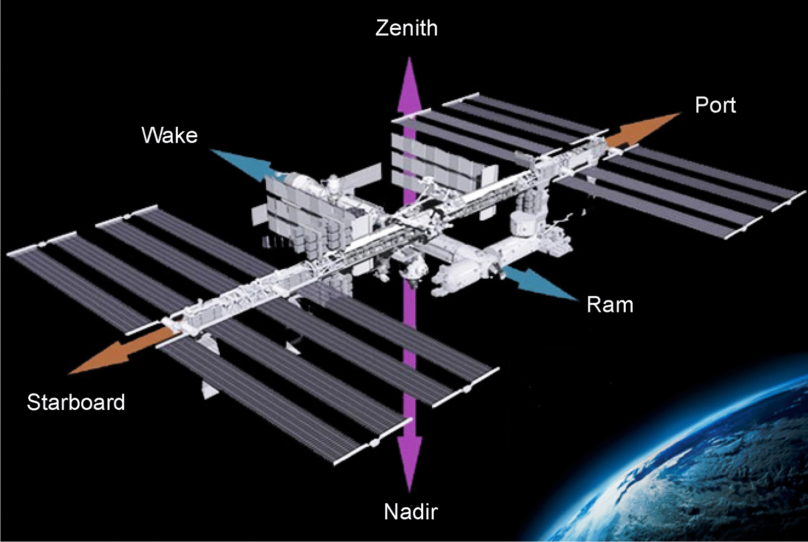
Ram, wake, zenith and nadir directions relative to the velocity vector. Atomic oxygen erosion is confined to ram-facing surfaces because the 4.5 eV collision energy comes from the vehicle velocity rather than from thermal motion of the gas [5]. Source: [5]. Public domain (NASA).
Erosion yield Ey is the volume removed per incident atom. Flight values from MISSE 2 (3.95 years, 16 August 2001 to 30 July 2005, ram fluence 8.43e21 atoms/cm2) [5]:
| Material | Erosion yield (cm3/atom) | Source |
|---|---|---|
| Polyoxymethylene | 9.14e-24 | [5] |
| Polycarbonate | 4.29e-24 | [4] |
| Epoxy, Hysol EA956 | 4.21e-24 | [4] |
| Mylar, PET | 3.01e-24 | [4] |
| Kapton H (reference material) | 3.00e-24 | [5] |
| PEEK | 2.99e-24 | [4] |
| Kapton HN | 2.81e-24 | [4] |
| ECTFE, Halar | 1.79e-24 | [4] |
| ETFE, Tefzel | 9.61e-25 | [4] |
| FEP Teflon | 2.00e-25 | [4] |
| PTFE | 1.42e-25 | [4] |
| DC 93-500 silicone | 3.81e-27 | [5] |
At the MISSE 2 fluence, a Kapton H surface loses about 25 micrometers [4]. Silicones survive because atomic oxygen converts the surface to a glassy silicate that passivates the layer below, at the cost of mud-tile cracking of that layer under strain [5]. Kapton H density of 1.4273 g/cm3 is the conversion used between measured mass loss and thickness loss.
The ground facility against orbit, on the same 39 polymers
Section titled “The ground facility against orbit, on the same 39 polymers”A radio-frequency plasma asher is the ground facility that stands in for orbit when a material has to be screened before flight, and the MISSE 2 PEACE experiment is the one case where the same 39 polymers were run in both [20]. The asher yield was higher than the space yield for every one of the 39, by a factor between 1.02 and 37.1 [20]. Both halves are measurements: the flight yields are mass loss on vacuum-dehydrated samples of stated density and exposed area at one common fluence, and that fluence, the 8.43e21 atoms/cm2 above, was itself determined from the mass loss of two Kapton H witness samples on the tray rather than taken from an atmospheric model. The asher yields are relative to Kapton H, with the samples in metal holders and the asher operated on air.
The direction is systematic and the size is not. Ground atomic oxygen testing overestimates erosion for every material in this set, but by a material-dependent factor, so the overestimate cannot be divided out: the fluoropolymers sit at 6.1 to 8.0, Kevlar at 24.0 and white Tedlar at 37.1 [20]. Two consequences follow for a designer. An asher screening pass is a conservative bound on erosion and nothing more. And two materials ranked against each other by asher yield can be ranked wrongly, because a 37-fold error and a 1.02-fold error appear in the same table [20]. Kevlar is a woven fabric rather than a film, and the source reads its position near the top of that list as weave geometry being what a ground facility fails to reproduce. That is an inference drawn from the ranking, not a separate experiment.
Mass loss is not a usable erosion metric for silicones at all. A silicone typically does not lose weight in atomic oxygen, because the surface converts to the glassy SiOx layer described above, so a mass-loss ranking places silicones among the most durable materials while that layer is shrinking and cracking to expose the substrate; nanomechanical surface hardness is used instead to set ground-facility equivalent fluences [20]. What changes optically is measurable. An uncovered DC 93-500 silicone sample on the MISSE 2 ram tray went from a solar absorptance of 0.005 before flight to 0.033 to 0.037 after four years [5], a factor of about seven, with total reflectance barely changed and the surface crazed into mud tiles.
Ram fluence scales with mission duration and solar activity: MISSE 4 accumulated 2.15e21 atoms/cm2 in 1.04 years and MISSE 8 accumulated 4.62e21 atoms/cm2 in 2.14 years [5]. On LDEF, inorganic coatings including aluminum, nickel and SiO2 protected T300/934 graphite epoxy from atomic oxygen with negligible mass penalty [6]. MISSE 2 samples also accumulated 1400 equivalent sun hours of solar exposure, and erosion yield for several polymers rose with combined solar exposure and temperature rather than with atomic oxygen fluence alone [5].
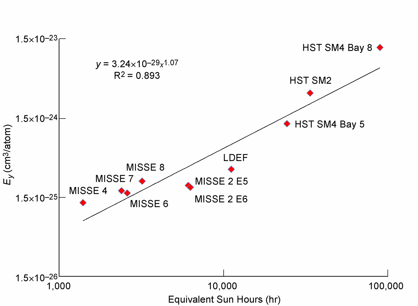
Erosion yield of FEP Teflon against accumulated solar exposure in equivalent sun hours, across several flight experiments. Yield rises with solar exposure, so an atomic oxygen fluence alone does not predict thickness loss for this material. Source: [5]. Public domain (NASA).
Thermal cycling
Section titled “Thermal cycling”An orbiting structure passes through eclipse roughly every 90 minutes [6]. LDEF accumulated about 34,000 thermal cycles in 5.8 years, over a range of -20 to 160 F (about -29 to 71 C) with a +/-20 F band on those limits [6]. The recorded failure modes were microcracking of composites and delamination of some dielectric and metallic coatings; the aluminized graphite-epoxy noted above survived the full cycle count without coating delamination. Cycling acts synergistically with atomic oxygen, ultraviolet, vacuum and contamination rather than independently.
Heat rejection is radiative because there is no convecting medium. The ISS US On-Orbit Segment rejects heat through the External Active Thermal Control System, two independent mechanically pumped single-phase liquid ammonia loops, each serving three radiators of eight panels, with each radiator carrying two flow paths [16]. Radiator orientation is controlled by the Thermal Radiator Rotary Joint, either parked at a fixed angle or in Autotrack, which adjusts the angle to maximize heat rejection against the moving sink direction. A robot on the outside of such a vehicle has the same constraint: heat generated in an actuator leaves only by conduction to a radiating surface.
Ionizing radiation
Section titled “Ionizing radiation”Total dose in a 51.6 deg, 400 km orbit originates primarily in the trapped belts, with one solar particle event assumed to occur per mission and add to it [13]. Design limits for the LEO-ISS orbit give a daily integral trapped proton fluence of 1.66e8 protons/cm2 above 0.1 MeV and 5.40e7 protons/cm2 above 0.5 MeV, external to the vehicle [13]. LDEF returned an integrated trapped electron and proton dose of 2.5e5 rad at the vehicle ends against less than 10 rad from cosmic rays over the same 5.8 years [6].
Single event effects, not total dose, set the avionics problem in LEO. ISS screens assembled articles rather than de-lidded parts, in 200 MeV proton beams: protons of 200 to 500 MeV pass through packages, boards and even box enclosures at nearly full energy, and roughly one in 289,000 of them strikes a nucleus inside a device and makes the short-range, high-LET reaction products that cause the upsets [10]. Heavy ion testing runs at linear energy transfer between 60 and 100 MeV cm2/mg at beam energies near 12 MeV/nucleon, and devices sensitive to single event latchup are screened against an LET threshold of 36 MeV cm2/mg [11]. Large solar energetic particle events deliver of order 2.5e7 protons/cm2 above 10 MeV [12].
Trapped-particle models carry stated error against flight dosimetry. Thermoluminescent dosimeters on LDEF read about a factor of two above the AP8MIN proton prediction at depths from 0.5 g/cm2, the measured trailing-to-leading dose ratio was 2.4 against 1.4 predicted, and AE8MIN agreed with thin-shielding doses within about a factor of two, possibly affected by dosimeter saturation [24]. NASA’s 2021 hardness assurance guidance builds on AE8 and AP8, acknowledges the systematic uncertainty from that choice without quantifying it, and contains no part-level test data [27].
Internal, or deep dielectric, charging is a separate mechanism from surface charging. Electrons near 100 keV penetrate 3 mils of aluminum and those near 1 MeV penetrate 80 mils, depositing charge in dielectrics behind the outer shell [9]. The design threshold derived from CRRES data is 2e10 electrons/cm2 accumulated over 10 hours, equivalent to an average flux of 5e5 electrons/cm2/s.
Plasma and surface charging
Section titled “Plasma and surface charging”The ionosphere at ISS altitude has an electron density near 1e11 m-3 and an electron temperature near 990 K, measured simultaneously by the wide and narrow Langmuir probes of the Floating Potential Measurement Unit [8]. Those instruments cover 1e9 to 5e12 m-3 and 500 to 3000 K, with the floating potential probe spanning -180 to +180 V.
Two mechanisms drive the ISS structure negative. The 160 V photovoltaic array strings collect electrons at their exposed high-potential ends, and motion across the geomagnetic field induces a potential of about -10 V on the pressurized truss with a 30 V variation tip to tip across the arrays [7]. Structure potential is clamped by two plasma contactor units emitting below 0.1 A nominally, with a maximum observed discharge current of 100 mA per orbit. With the contactors off, the largest floating potential recorded by the Floating Potential Probe in 2001 was -23 V, at eclipse exit; the effective ion collection area of the ISS structure, the term that sets the electron loss balance, is 35 m2; and above about 160 V, snapover raises the conductivity of exposed array surfaces and increases collection [7].
Charging also bears on dust mitigation hardware. Twelve Electrodynamic Dust Shield panels flew on MISSE-11 in the ISS wake position, two energized at 4 kV and 10 Hz [25]. The glass panel drew current on orbit that matched its ground vacuum behavior, while the Kapton panel showed more than fifteen unexplained current spikes on its first run [25]. The report is preliminary, with two on-orbit runs.
Charging matters for robotics because an EVA suit, a grapple fixture or a manipulator end effector making first contact with a differently charged surface completes a circuit that was previously open.
Meteoroids and orbital debris
Section titled “Meteoroids and orbital debris”The meteoroid environment model MEM 3 covers particle masses from 1e-6 to 10 g, the range able to damage a spacecraft, and gives an average impact speed in low Earth orbit of 19 km/s [14]. Particles below 1e-6 g are assigned a density of 2 g/cm3. Showers contribute about 1 percent of total flux at the 1 microgram limit and less than 10 percent for particles below 0.5 cm, so the sporadic background dominates design [14].
LDEF recorded 34,336 micrometeoroid and debris impacts over 5.8 years [6]; the comparison of MEM against that record works from craters with lip diameters above 1000 microns, a limiting crater diameter of 750 microns [15]. ISS radiators carry MMOD strikes on all panels, and to date no strike has produced a leak in a radiator flow path [16]. Impacts are not uniformly distributed in time; the LDEF record showed them arriving in temporal bursts [6].
Flux depends on orientation as strongly as atomic oxygen does. A manipulator parked in one attitude for months accumulates a different exposure on each face.
Vacuum tribology
Section titled “Vacuum tribology”At 1e-4 to 1e-7 torr [6] there is no adsorbed water or oxide-replenishing atmosphere on a freshly exposed metal surface, and boundary lubrication must be supplied by a fluid that does not evaporate. Vapor pressure therefore sets the choice of lubricant before viscosity does [17].
Friction against ambient pressure is not monotonic, so a single vacuum figure does not describe a mechanism that sees a range of pressures. AISI 52100 steel sliding on itself gives a friction coefficient of 0.45 in laboratory air at 760 mm Hg, falls to about 0.2 between 1e-1 and 1e-2 mm Hg, and rises again to 0.375 at 5e-7 mm Hg, all measured on a 3/16 in radius hemispherical rider against a 2.5 in rotating disk at 1000 g load, 390 ft/min and room temperature [18]. The rise at the low end is the residual oxygen supply becoming too thin to re-oxidize metal transferred to the rider, and the whole curve sits six to eight orders of magnitude above the roughly 1e-14 mm Hg the same authors give for space.
Below the oxide the contact welds. Matched copper single crystals contacted at 1e-11 torr under a 50 g load with a 10 second dwell give an adhesion coefficient, breakaway force divided by applied load, of 1.02 before any sliding, and after sliding 0.735 cm at 0.001 cm/s the matched (100) pair exceeds 130 against 10.5 for the matched (111) pair [19]. The specimens are 99.999 percent metals cleaned in place by argon ion bombardment and the upper values are the limit of the apparatus rather than measurements, so the set bounds what a plated, machined and handled surface can do rather than predicting it. The ratio between the static and post-sliding values is why a fretting interface is treated as the cold welding risk in an orbital mechanism and a static clamped one is not.
Flight bears that distinction out. A French experiment on LDEF held aluminum, copper, titanium, stainless steel, copper beryllium, silver alloy and palladium washer pairs in static loaded contact at 25 to 135 MPa under Belleville springs for 69 months in low Earth orbit [21], with no sliding motion. Post-flight metallurgical examination of every flight and control pair found no cold welding event, and the ground controls held under vacuum for the same 69 months found none either; the experimenters attribute the null result to the oxide never being removed, because nothing slid [21]. The same report’s review of prior on-orbit experience found no documented significant cold welding failure on a US spacecraft, every reported seizure tracing to vibration-driven fretting or to galling after loss of lubricant. That review is a literature survey rather than a measurement.
| Lubricant | Vapor pressure at 150 C (Pa) | Kinematic viscosity at 40 / 100 C (cSt) | Source |
|---|---|---|---|
| PFPAE 815Z | 3.5e-6 | not stated | [17] |
| Trisilahydrocarbon 2-94-96 | 3.1e-5 | 133 / 20 | [17] |
| Pentasilahydrocarbon MJD990405 | 1.9e-5 | 206 / 31 | [17] |
| Multiply alkylated cyclopentane, Pennzane P2001A | 2.3e-3 | 108 / 15 | [17] |
Extrapolated to 25 C, the trisilahydrocarbon sits at 1.1e-8 Pa and pentasilahydrocarbon MJD991029 at 3.0e-12 Pa [17]. Film thickness under Hertzian contact depends on the pressure-viscosity coefficient, measured at 16 and 11 GPa-1 at 21 and 40 C for 2-94-96 against 11 and 8.5 GPa-1 for Pennzane P2001A.
Wear testing is run in vacuum because the result changes with ambient chemistry. Spiral orbit tribometer runs at below 1.3e-6 Pa, 200 rpm, 23 C, 1.5 GPa mean Hertzian stress and a 50 microgram oil charge per ball take a friction coefficient of 0.28 as the failure criterion [17]. In a reciprocating tribometer at 250 N, 0.7 GPa peak Hertzian stress, 6 Hz and 100 C, a tetrasilahydrocarbon produced a 0.71 mm2 wear scar against 1.02 mm2 for Pennzane 2001A. A bearing test at 1e-5 Pa, 600 rpm, 89 N axial load, 75 C and 20 mg free oil ran about 1000 hours on a pentasilahydrocarbon without measurable degradation.
Lubricated hardware returned from orbit
Section titled “Lubricated hardware returned from orbit”One set of lubricated hardware has come back. LDEF carried Castrol Braycote 601, a PTFE filled perfluoropolyether grease, on trailing edge drive shafts, ultraviolet exposed with negligible atomic oxygen [21]. The returned grease had a lower base oil viscosity than its control, read as ultraviolet chain scission of the polyether; infrared showed no new carbonyl and therefore no oxidation, but new peaks at 1100 to 1400 wavenumbers suggest the PTFE filler itself degraded, and new DSC endotherms appeared near 106 C and 211 C, the second unexplained. The grease had darkened to black and the cause was not identified [21].
Bonded dry film did worse than either. Everlube 620, a heat-cured MoS2 film in a proprietary organic binder, was gone after the same 69 months on the same trailing edge: only traces of MoS2 remained in the machining grooves, too little to test, the binder having been decomposed by ultraviolet and evaporated [21]. That is the one clear lubricant loss on LDEF and it happened where atomic oxygen fluence was negligible. Tungsten disulfide dry film on the grapple shafts, by contrast, was intact with no discernible difference between ram and trailing surfaces, but no surface analysis and no friction test was run on it, so it is a survival observation and not a tribological result.
A friction number did survive. DuPont Vespel SP-21, graphite filled polyimide, exposed on a trailing edge tray for 69 months, returned a coefficient of friction unchanged from its control at about 0.15 after run-in, over 10,000 cycles against two unflown controls [21]. The friction test was run on the ground in laboratory air, so the 0.15 carries the same room-temperature-air caveat as any bench figure and is not a vacuum value; what the flight establishes is that 69 months of orbital ultraviolet and vacuum did not change it [21].
What is not established
Section titled “What is not established”Flight lubricant evidence is one set of LDEF hardware exposed largely to ultraviolet with negligible atomic oxygen [21], so lubricant behavior on a ram-facing mechanism over years is not covered by returned hardware. The ground-to-orbit atomic oxygen factor varies from 1.02 to 37.1 by material [20] and cannot be divided out. The ISS charging model rests on a lumped 35 m2 collection area fitted to data from December 2000 to April 2001, before the probe failed [8]. The MEM validation against LDEF shows a ram-side underprediction that would need a debris share of about 75 percent to reconcile, and no usable debris model exists for 1984 to 1990 to test that [15]. The LDEF dose comparison used 1990s-era trapped-particle models [24]. Microgravity robotics results on ISS are largely narrative: Robonaut 2 reports no success rates [30], and ground analogs omit the non-gravitational environment [28].
References
- McPherson, K., Kelly, E. and Keller, J. (2009). Acceleration Environment of the International Space Station
. AIAA Aerospace Sciences Meeting including The New Horizons Forum and Aerospace Exposition, 20120012936. Source
BibTeX
@inproceedings{mcpherson2009acceleration, title = {Acceleration Environment of the International Space Station}, author = {McPherson, Kevin and Kelly, Eric and Keller, Jennifer}, booktitle = {AIAA Aerospace Sciences Meeting including The New Horizons Forum and Aerospace Exposition}, number = {20120012936}, institution = {NASA}, year = {2009}, doi = {10.2514/6.2009-957}, abstract = {Measurement of the microgravity acceleration environment on the International Space Station has been accomplished by two accelerometer systems since 2001. The Microgravity Acceleration Measurement System records the quasi-steady microgravity environment, including the influences of aerodynamic drag, vehicle rotation, and venting effects. Measurement of the vibratory/transient regime, comprised of vehicle, crew, and equipment disturbances, has been accomplished by the Space Acceleration Measurement System-II. Until the arrival of the Columbus Orbital Facility and the Japanese Experiment Module, the location of these sensors, and therefore, the measurement of the microgravity acceleration environment, has been limited to within the United States Laboratory. Japanese Aerospace Exploration Agency has developed a vibratory acceleration measurement system called the Microgravity Measurement Apparatus which will be deployed within the Japanese Experiment Module to make distributed measurements of the Japanese Experiment Module's vibratory acceleration environment. Two Space Acceleration Measurement System sensors from the United States Laboratory will be re-deployed to support vibratory acceleration data measurement within the Columbus Orbital Facility. The additional measurement opportunities resulting from the arrival of these new laboratories allows Principal Investigators with facilities located in these International Space Station research laboratories to obtain microgravity acceleration data in support of their sensitive experiments. The Principal Investigator Microgravity Services project, at NASA Glenn Research Center, in Cleveland, Ohio, has supported acceleration measurement systems and the microgravity scientific community through the processing, characterization, distribution, and archival of the microgravity acceleration data obtained from the International Space Station acceleration measurement systems. This paper summarizes the PIMS capabilities available to the International Space Station scientific community, introduces plans for extending microgravity analysis results to the newly arrived scientific laboratories, and provides summary information for known microgravity environment disturbers.} } - DeLombard, R., McPherson, K., Hrovat, K., Moskowitz, M., Rogers, M. J. B. and Reckart, T. (1997). Microgravity Environment Description Handbook
. NASA, NASA-TM-107486. Source
BibTeX
@techreport{delombard1997microgravity, title = {Microgravity Environment Description Handbook}, author = {DeLombard, Richard and McPherson, Kevin and Hrovat, Kenneth and Moskowitz, Milton and Rogers, Melissa J. B. and Reckart, Timothy}, number = {NASA-TM-107486}, institution = {NASA}, year = {1997}, url = {https://ntrs.nasa.gov/citations/19970022250}, abstract = {The Microgravity Measurement and Analysis Project (MMAP) at the NASA Lewis Research Center (LeRC) manages the Space Acceleration Measurement System (SAMS) and the Orbital Acceleration Research Experiment (OARE) instruments to measure the microgravity environment on orbiting space laboratories. These laboratories include the Spacelab payloads on the shuttle, the SPACEHAB module on the shuttle, the middeck area of the shuttle, and Russia's Mir space station. Experiments are performed in these laboratories to investigate scientific principles in the near-absence of gravity. The microgravity environment desired for most experiments would have zero acceleration across all frequency bands or a true weightless condition. This is not possible due to the nature of spaceflight where there are numerous factors which introduce accelerations to the environment. This handbook presents an overview of the major microgravity environment disturbances of these laboratories. These disturbances are characterized by their source (where known), their magnitude, frequency and duration, and their effect on the microgravity environment. Each disturbance is characterized on a single page for ease in understanding the effect of a particular disturbance. The handbook also contains a brief description of each laboratory.} } - Foster, W. (2009). Space Acceleration Measurement System-II
. NASA, 20090014818. Source
BibTeX
@techreport{foster2009space, title = {Space Acceleration Measurement System-II}, author = {Foster, William}, number = {20090014818}, institution = {NASA}, year = {2009}, url = {https://ntrs.nasa.gov/citations/20090014818}, abstract = {Space Acceleration Measurement System (SAMS-II) is an ongoing study of the small forces (vibrations and accelerations) on the ISS that result from the operation of hardware, crew activities, as well as dockings and maneuvering. Results will be used to generalize the types of vibrations affecting vibration-sensitive experiments. Investigators seek to better understand the vibration environment on the space station to enable future research.} } - deGroh, K. K., Banks, B. A., McCarthy, C. E., Rucker, R. N., Roberts, L. M. and Berger, L. A. (2006). MISSE PEACE Polymers Atomic Oxygen Erosion Results
. MISSE Post-Retrieval Conference, NASA/TM-2006-214482. Source
BibTeX
@inproceedings{degroh2006misse, title = {MISSE PEACE Polymers Atomic Oxygen Erosion Results}, author = {deGroh, Kim K. and Banks, Bruce A. and McCarthy, Catherine E. and Rucker, Rochelle N. and Roberts, Lily M. and Berger, Lauren A.}, booktitle = {MISSE Post-Retrieval Conference}, number = {NASA/TM-2006-214482}, institution = {NASA}, address = {Orlando, FL}, year = {2006}, url = {https://ntrs.nasa.gov/citations/20070002707}, abstract = {Forty-one different polymer samples, collectively called the Polymer Erosion and Contamination Experiment (PEACE) Polymers, have been exposed to the low Earth orbit (LEO) environment on the exterior of the International Space Station (ISS) for nearly 4 years as part of Materials International Space Station Experiment 2 (MISSE 2). The objective of the PEACE Polymers experiment was to determine the atomic oxygen erosion yield of a wide variety of polymeric materials after long term exposure to the space environment. The polymers range from those commonly used for spacecraft applications, such as Teflon (DuPont) FEP, to more recently developed polymers, such as high temperature polyimide PMR (polymerization of monomer reactants). Additional polymers were included to explore erosion yield dependence upon chemical composition. The MISSE PEACE Polymers experiment was flown in MISSE Passive Experiment Carrier 2 (PEC 2), tray 1, on the exterior of the ISS Quest Airlock and was exposed to atomic oxygen along with solar and charged particle radiation. MISSE 2 was successfully retrieved during a space walk on July 30, 2005, during Discovery s STS-114 Return to Flight mission. Details on the specific polymers flown, flight sample fabrication, pre-flight and post-flight characterization techniques, and atomic oxygen fluence calculations are discussed along with a summary of the atomic oxygen erosion yield results. The MISSE 2 PEACE Polymers experiment is unique because it has the widest variety of polymers flown in LEO for a long duration and provides extremely valuable erosion yield data for spacecraft design purposes.} } - de Groh, K. K. and Banks, B. A. (2019). Atomic Oxygen Erosion Data from the MISSE 2-8 Missions
. NASA, 20190025445. Source
BibTeX
@techreport{degroh2019atomic, title = {Atomic Oxygen Erosion Data from the MISSE 2-8 Missions}, author = {de Groh, Kim K. and Banks, Bruce A.}, number = {20190025445}, institution = {NASA}, year = {2019}, url = {https://ntrs.nasa.gov/citations/20190025445}, abstract = {Polymers and other oxidizable materials on the exterior of spacecraft in the low Earth orbit (LEO) space environment can be eroded from reaction with atomic oxygen (AO). Therefore, in order to design durable spacecraft it is important to know the extent of erosion that will occur during a mission. This can be determined by knowing the LEO AO erosion yield, E(sub y) (volume loss per incident oxygen atom), of materials susceptible to AO reaction. In addition, recent flight experiments have shown that the AO E(sub y) can vary with the AO fluence and/or solar exposure. Therefore obtaining AO E(sub y) data for materials flown on various spaceflight missions is important. NASA Glenn Research Center has flown numerous experiments as part of the Materials International Space Station Experiment (MISSE) missions on the exterior of the International Space Station to characterize the LEO E(sub y) of polymers, composites, protective coatings, and other spacecraft materials. This report provides a summary of the erosion data for ram samples from six Glenn polymer experiments flown as part of MISSE 2, 4, 6, 7, and 8. A total of 71 types of materials with 111 E(sub y) values are provided. The E(sub y) values for uncoated polymers range from 3.81×10(exp –27) cu cm/atom for DC 93-500 silicone exposed to an AO fluence of 4.62×10(exp 21) atoms/sq cm on MISSE 8 to 9.14×10(exp –24) cu cm/atom for polyoxymethylene (POM) exposed to an AO fluence of 8.43×10(exp 21) atoms/sq cm on MISSE 2. One polymer, Triton oxygen resistant, low modulus (TOR(TM) LM), experienced mass gain when exposed to an AO fluence of 2.15×10(exp 21) atoms/sq cm on MISSE 4. In many cases the same material was flown on numerous missions so that trends for E(sub y) versus AO fluence and/or solar exposure can be determined, along with temperature effects. } } - Stein, B. A. (1992). An interim overview of LDEF materials findings
. NASA, NASA-TM-107664. Source
BibTeX
@techreport{stein1992interim, title = {An interim overview of LDEF materials findings}, author = {Stein, Brad A.}, number = {NASA-TM-107664}, institution = {NASA}, year = {1992}, url = {https://ntrs.nasa.gov/citations/19930009140}, abstract = {The flight and retrieval of the National Aeronautics and Space Administration's Long Duration Exposure Facility (LDEF) provided an opportunity for the study of the low-Earth orbit (LEO) environment and long-duration space environmental effects (SEE) on materials that is unparalleled in the history of the U.S. Space Program. The remarkable flight attitude stability of LDEF enables specific analyses of various individual and combined effects of LEO environmental parameters on identical materials on the same space vehicle. This paper provides an overview of the interim LDEF materials findings of the Principal Investigators and the Materials Special Investigation Group. In general, the LDEF data is remarkably consistent; LDEF will provide a 'benchmark' for materials design data bases for satellites in low-Earth orbit. Some materials were identified to be encouragingly resistant to LEO SEE for 5.8 years; other 'space qualified' materials displayed significant environmental degradation. Molecular contamination was widespread; LDEF offers an unprecedented opportunity to provide a unified perspective of unmanned LEO spacecraft contamination mechanisms. New material development requirements for long-term LEO missions have been identified and current ground simulation testing methods/data for new, durable materials concepts can be validated with LDEF results. LDEF findings are already being integrated into the design of Space Station Freedom.} } - Barsamian, H., Mikatarian, R. R., Alred, J., Minow, J. and Koontz, S. (2004). ISS Plasma Interaction: Measurements and Modeling
. Spacecraft Charging and Technology Conference, 20040111048. Source
BibTeX
@inproceedings{barsamian2004iss, title = {ISS Plasma Interaction: Measurements and Modeling}, author = {Barsamian, H. and Mikatarian, Ronald R. and Alred, J. and Minow, J. and Koontz, S.}, booktitle = {Spacecraft Charging and Technology Conference}, number = {20040111048}, institution = {NASA}, year = {2004}, url = {https://ntrs.nasa.gov/citations/20040111048}, abstract = {Ionospheric plasma interaction effects on the International Space Station are discussed in the following paper. The large structure and high voltage arrays of the ISS represent a complex system interacting with LEO plasma. Discharge current measurements made by the Plasma Contactor Units and potential measurements made by the Floating Potential Probe delineate charging and magnetic induction effects on the ISS. Based on theoretical and physical understanding of the interaction phenomena, a model of ISS plasma interaction has been developed. The model includes magnetic induction effects, interaction of the high voltage solar arrays with ionospheric plasma, and accounts for other conductive areas on the ISS. Based on these phenomena, the Plasma Interaction Model has been developed. Limited verification of the model has been performed by comparison of Floating Potential Probe measurement data to simulations. The ISS plasma interaction model will be further tested and verified as measurements from the Floating Potential Measurement Unit become available, and construction of the ISS continues.} } - Wright, K. H. J., Swenson, C., Thompson, D., Barjatya, A., Koontz, S. L., Schneider, T., Vaughn, J., Minow, J., Craven, P., Coffey, V., Parker, L. and Bui, T. (2007). Initial Results from the Floating Potential Measurement Unit aboard the International Space Station
. Spacecraft Charging and Technology Conference, 20070032723. Source
BibTeX
@inproceedings{wright2007initial, title = {Initial Results from the Floating Potential Measurement Unit aboard the International Space Station}, author = {Wright, Kenneth H., Jr. and Swenson, Charles and Thompson, Don and Barjatya, Aroh and Koontz, Steven L. and Schneider, Todd and Vaughn, Jason and Minow, Joseph and Craven, Paul and Coffey, Victoria and Parker, Linda and Bui, Them}, booktitle = {Spacecraft Charging and Technology Conference}, number = {20070032723}, institution = {NASA}, address = {Biarritz}, year = {2007}, url = {https://ntrs.nasa.gov/citations/20070032723}, abstract = {The Floating Potential Measurement Unit (FPMU) is a multi-probe package designed to measure the floating potential of the 1nternational Space Station (ISS) as well as the density and temperature of the local ionospheric plasma environment. The role oj the FPMU is to provide direct measurements of ISS spacecraft charging as continuing construction leads to dramatic changes in ISS size and configuration. FPMU data are used for refinement and validation of the ISS spacecraft charging models used to evaluate the severity and frequency of occurrence of ISS charging hazards. The FPMU data and the models are also used to evaluate the effectiveness of proposed hazard controls. The FPMU consists of four probes: a floating potential probe, two Langmuir probes. and a plasma impedance probe. These probes measure the floating potential of the ISS, plasma density, and electron temperature. Redundant measurements using different probes support data validation by inter-probe comparisons. The FPMU was installed by ISS crewmembers, during an ExtraVehicular Activity, on the starboard (Sl) truss of the ISS in early August 2006, when the ISS incorporated only one 160V US photovoltaic (PV) array module. The first data campaign began a few hours after installation and continued for over five days. Additional data campaigns were completed in 2007 after a second 160V US PV array module was added to the ISS. This paper discusses the general performance characteristics of the FPMU as integrated on ISS, the functional performance of each probe, the charging behavior of the ISS before and after the addition of a second 160V US PV array module, and initial results from model comparisons.} } - Whittlesey, A. and Garrett, H. B. (1996). NASA's Technical Handbook for Avoiding On-Orbit ESD Anomalies Due to Internal Charging Effects
. NASA, 20000055759. Source
BibTeX
@techreport{whittlesey1996nasa, title = {NASA's Technical Handbook for Avoiding On-Orbit ESD Anomalies Due to Internal Charging Effects}, author = {Whittlesey, Albert and Garrett, Henry B.}, number = {20000055759}, institution = {NASA}, year = {1996}, url = {https://ntrs.nasa.gov/citations/20000055759}, abstract = {This paper describes NASA-HDBK-4002, "Avoiding Problems Caused by Spacecraft On-Orbit Internal Charging Effects". The handbook includes a description of internal charging and why it is of concern to spacecraft designers. It also suggests how to determine when a project needs to consider internal spacecraft charging, it contains an electron penetration depth chart, rationale for a critical electron flux criterion, a worst-case geosynchronous electron plasma spectrum, general design guidelines, quantitative design guidelines, and a typical materials characteristics list. Appendices include a listing of some environment codes, electron transport codes, a discussion of geostationary electron plasma environments, a brief description of electron beam and other materials tests, and transient susceptibility tests. The handbook will be in the web page, hftp://standards.nasa.gov. A prior document, NASA TP2361 "Design Guidelines for Assessing and controlling Spacecraft Charging Effects", 1984, is in use to describe mitigation techniques for the effects of surface charging of satellites in space plasma environments. HDBK-4002 is meant to complement 2361 and together, the pair of documents describe both cause and mitigation designs for problems caused by energetic space plasmas.} } - Koontz, S. L., Suggs, R. M., Alred, J. W., Worthy, E. S., Boeder, P., Steagall, C. A., Hartman, W. A., Gingras, B. D. and Schmidl, W. D. (2018). The International Space Station Space Radiation Environment: Avionics Systems Performance in Low-Earth Orbit Single Event Effects (SEE) Environments
. International Conference on Environmental Systems, ICES-2018-69. Source
BibTeX
@inproceedings{koontz2018international, title = {The International Space Station Space Radiation Environment: Avionics Systems Performance in Low-Earth Orbit Single Event Effects (SEE) Environments}, author = {Koontz, Steven L. and Suggs, Robert M. and Alred, John W. and Worthy, Erica S. and Boeder, Paul and Steagall, Courtney A. and Hartman, William A. and Gingras, Benjamin D. and Schmidl, William D.}, booktitle = {International Conference on Environmental Systems}, number = {ICES-2018-69}, address = {Albuquerque, New Mexico}, year = {2018}, url = {https://ttu-ir.tdl.org/items/7fb5d403-ad77-4f6b-9cff-c70af5c04802} } - Reddell, B. D. (1999). Orbiter Avionics Radiation Handbook
. NASA, 20180002644. Source
BibTeX
@techreport{reddell1999orbiter, title = {Orbiter Avionics Radiation Handbook}, author = {Reddell, Brandon D.}, number = {20180002644}, institution = {NASA}, year = {1999}, url = {https://ntrs.nasa.gov/citations/20180002644}, abstract = {This handbook was assembled to document he radiation environment for design of Orbiter avionics. It also maps the environment through vehicle shielding and mission usage into discrete requirements such as total dose. Some details of analytical techniques for calculating radiation effects are provided. It is anticipated that appropriate portions of this document will be added to formal program specifications. } } - Adams, J. H. J. (1988). Current models of the intensely ionizing particle environment in space
. NASA, 19890019087. Source
BibTeX
@techreport{adams1988current, title = {Current models of the intensely ionizing particle environment in space}, author = {Adams, James H., Jr.}, number = {19890019087}, institution = {NASA}, year = {1988}, url = {https://ntrs.nasa.gov/citations/19890019087}, abstract = {The Cosmic Ray Effects on MicroElectronics (CREME) model that is currently in use to estimate single event effect rates in spacecraft is described. The CREME model provides a description of the radiation environment in interplanetary space near the orbit of the earth that contains no major deficiencies. The accuracy of the galactic cosmic ray model is limited by the uncertainties in solar modulation. The model for solar energetic particles could be improved by making use of all the data that has been collected on solar energetic particle events. There remain major uncertainties about the environment within the earth's magnetosphere, because of the uncertainties over the charge states of the heavy ions in the anomalous component and solar flares, and because of trapped heavy ions. The present CREME model is valid only at 1 AU, but it could be extended to other parts of the heliosphere. There is considerable data on the radiation environment from 0.2 to 35 AU in the ecliptic plane. This data could be used to extend the CREME model.} } - NASA. (2020). Cross-Program Design Specification for Natural Environments (DSNE), Revision G
. NASA Marshall Space Flight Center. Source
BibTeX
@techreport{nasa2020cross, title = {Cross-Program Design Specification for Natural Environments (DSNE), Revision G}, author = {{NASA}}, institution = {NASA Marshall Space Flight Center}, year = {2020}, url = {https://ntrs.nasa.gov/citations/20200000867}, abstract = {The DSNE completes environment-related specifications for architecture, system-level, and lower-tier documents by specifying the ranges of environmental conditions that must be accounted for by NASA ESD Programs. To assure clarity and consistency, and to prevent requirements documents from becoming cluttered with extensive amounts of technical material, natural environment specifications have been compiled into this document. The intent is to keep a unified specification for natural environments that each Program calls out for appropriate application.} } - Moorhead, A. V. (2020). NASA Meteoroid Engineering Model (MEM) Version 3
. NASA, NASA/TM-2020-220555. Source
BibTeX
@techreport{moorhead2020nasa, title = {NASA Meteoroid Engineering Model (MEM) Version 3}, author = {Moorhead, A. V.}, number = {NASA/TM-2020-220555}, institution = {NASA}, year = {2020}, url = {https://ntrs.nasa.gov/citations/20200000563}, abstract = {The Meteoroid Engineering Model (MEM) version 3 is NASA’s most current and accurate model of the meteoroid environment. MEM 3 supersedes all previous versions of MEM, including MEM Release 2.0 (MEMR2), MEM Release 1.0c (MEMR1c), and previously internally controlled and released versions of MEMCxP v2.0 and LunarMEM v2.0. Earlier versions of MEM superseded older models of the meteoroid environment such as the Grün model and its derivative, Technical Memo 4527 (hereafter abbreviated as TM 4527) [1]. Prior to the establishment of the NASA Meteoroid Environment Office (MEO), NASA’s meteoroid environment models relied on a simple empirical expression derived from [2], as described in [3] and later in [1]. This expression describes the meteoroid flux incident on a flat plate near 1 au. TM 4527 assumes an isotropic environment, making the orientation of the plate irrelevant [4]. The flux was combined with scale factors to account for the reduction in flux occurring when the Earth shields the spacecraft from a portion of the meteoroid environment and the enhancement in flux due to the focusing effect of Earth’s gravitational field. TM 4527 also introduced a crude, piecewise meteoroid speed distribution with an average velocity of 19 km/s for an orbiting spacecraft based on [5]. Finally, TM 4527 assumed a three-step density distribution in which dust particles smaller than 10−6 g have a density of 2 g/cu cm, micrometeoroids between 10−6 g and 0.01 g have a density of 1 g/cu cm, and meteoroids larger than 0.01 g have a density of 0.5 g/cm3. Thus, the meteoroid model presented in TM 4527 was assembled from multiple independent sources. The model of TM 4527 was also used for years in Space Station risk assessments, and is described in Space Station Specification (SSP) 30425.} } - Ehlert, S., Moorhead, A. and Cooke, W. J. (2017). A Comparison of Results From NASA's Meteoroid Engineering Model to the LDEF Cratering Record
. European Conference on Space Debris, 20170004455. Source
BibTeX
@inproceedings{ehlert2017comparison, title = {A Comparison of Results From NASA's Meteoroid Engineering Model to the LDEF Cratering Record}, author = {Ehlert, S. and Moorhead, A. and Cooke, W. J.}, booktitle = {European Conference on Space Debris}, number = {20170004455}, organization = {ESA Space Debris Office}, address = {Darmstadt}, year = {2017}, url = {https://ntrs.nasa.gov/citations/20170004455}, abstract = {NASA's Long Duration Exposure Facility (LDEF) has provided an extensive record of the meteoroid environment in low Earth orbit. LDEF's combination of fixed orientation, large collecting area, and long lifetime imposes constraints on the absolute flux of potentially hazardous meteoroids. The relative impact rate on each of LDEF's fourteen surfaces arises from the underlying velocity distribution and directionality of the meteoroid environment. For the first time, we model the meteoroid environment encountered by LDEF over its operational lifetime using NASA's Meteoroid Engineering Model Release 2 (MEMR2) and compare the model results with the observed craters of potentially hazardous meteoroids (i.e. crater diameters larger than approximately 0.75 mm). We discuss the extent to which the observations and model agree and how the impact rates across all of the LDEF surfaces may be utilized to help calibrate future versions of MEM.} } - Rodriguez, A. and Morton, R. (2025). ISS Radiator Face Sheet Anomaly Investigation and Return to Function
. International Conference on Environmental Systems, 20260002946. Source
BibTeX
@inproceedings{rodriguez2025iss, title = {ISS Radiator Face Sheet Anomaly Investigation and Return to Function}, author = {Rodriguez, Aaron and Morton, Richard}, booktitle = {International Conference on Environmental Systems}, number = {20260002946}, institution = {NASA}, year = {2025}, doi = {10.32865/2346/108957}, abstract = {Maintaining sufficient heat rejection on the International Space Station (ISS) is critical to the function of Low Earth Orbit station. The External Thermal Control System (EATCS) rejects the heat generated by the US On-orbit Segment (USOS) modules. The system uses ammonia to collect the heat and reject it to 6 radiators (3 on the Starboard side, 3 on the Port side). Each radiator is made up of 8 panels. In September of 2008, imagery of the Starboard Radiators was conducted and showed that one of the panels’ face sheets had peeled up from the internal honeycomb core structure. Out of an abundance of caution, the radiator was isolated from the rest of the EATCS and the ammonia was vented to space. Since the radiator was vented, periodic imagery of all radiator panels has taken place to monitor any changes in the face sheet and inspect for other radiator anomalies. In January 2025, after years of trending and inspections, the radiator will be reintegrated into the system and will reject heat. This paper will document the multi-year investigation that took place to determine root cause and mitigations implemented to reduce risk to the system. A summary of the data since the investigation will show rationale for reintegrating the radiator even with the damaged panel.} } - Jones, W. R. J., Jansen, M. J., Gschwender, L. J., Snyder, C. E. J., Sharma, S. K., Predmore, R. E. and Dube, M. J. (2001). The Tribological Properties of Several Silahydrocarbons for Use in Space Mechanisms
. Journal of Synthetic Lubrication, NASA/TM-2001-211196. Source
BibTeX
@article{jones2001tribological, title = {The Tribological Properties of Several Silahydrocarbons for Use in Space Mechanisms}, author = {Jones, W. R., Jr. and Jansen, M. J. and Gschwender, L. J. and Snyder, C. E., Jr. and Sharma, Shiv K. and Predmore, R. E. and Dube, Michael J.}, journal = {Journal of Synthetic Lubrication}, volume = {20}, number = {NASA/TM-2001-211196}, pages = {303-315}, institution = {NASA}, address = {Liege}, year = {2001}, doi = {10.1002/jsl.3000200404}, abstract = {Abstract Silahydrocarbons are members of a relatively new class of liquid lubricants with great potential for use in space mechanisms. They are unimolecular species consisting of silicon, carbon, and hydrogen. They possess unique wear, viscosity, and volatility properties while retaining the ability to solubilise conventional additives. The tribological properties of several members of this class, including tri‐, tetra‐, and penta‐compounds, are presented. These properties include viscosity‐temperature, viscosity—pressure, vapour pressure, lubricant life, traction, and reciprocating and four‐ball wear rates. Lubricant lifetimes were determined using a vacuum ball bearing simulator, the spiral orbit tribometer. Wear was measured using a Cameron Plint reciprocating tribometer and wear rates with a vacuum four‐ball tribometer. Conventional viscometry was used for viscosity—temperature measurements and a Knudsen cell for vapour pressure. Thermogravimetric analysis was also used for volatility measurements. Pressure—viscosity coefficients (α—values) were estimated from elastohydrodynamic lubrication film thickness measurements. These properties are compared to those of existing state‐of‐the‐art space lubricants.} } - Buckley, D. H., Swikert, M. and Johnson, R. L. (1962). Friction, Wear, and Evaporation Rates of Various Materials in Vacuum to 1e-7 mm Hg
. ASLE Transactions. Source
BibTeX
@article{buckley1962friction, title = {Friction, Wear, and Evaporation Rates of Various Materials in Vacuum to 1e-7 mm Hg}, author = {Buckley, Donald H. and Swikert, Max and Johnson, Robert L.}, journal = {ASLE Transactions}, volume = {5}, pages = {8--23}, year = {1962}, url = {https://ntrs.nasa.gov/citations/20150020881}, abstract = {The requirements for bearings and seals to operate in the environment of space dictate a new area for lubrication research. The low ambient pressures encountered in space can be expected to influence the behavior of oil, grease, and solid-film lubricants. The property of these materials most significantly affected by low ambient pressures is the evaporation rate. Various investigators have therefore measured the evaporation rates of oils and greases in vacuum as one method of establishing their relative merit for space applications (1-3). The results of this work have given some indication as to the oils and greases with the greatest stability at reduced ambient pressures. Only limited experimental work, however, has been reported in the literature for inorganic solids and soft metals which have potential use as solid lubricant films or coatings for hard alloy substrates [e.g. Reference ( 4 )]. In general, the evaporation rates of these materials would be lower than those of oils and greases. These films might therefore be very attractive as lubricants for high vacuum service.} } - Buckley, D. H. (1968). Influence of Crystal Structure, Orientation, and Solubility on Adhesion and Sliding Friction of Metal Single Crystals in Vacuum
. NASA Lewis Research Center, NASA TN D-4954. Source
BibTeX
@techreport{buckley1968influence, title = {Influence of Crystal Structure, Orientation, and Solubility on Adhesion and Sliding Friction of Metal Single Crystals in Vacuum}, author = {Buckley, Donald H.}, number = {NASA TN D-4954}, institution = {NASA Lewis Research Center}, year = {1968}, url = {https://ntrs.nasa.gov/citations/19680011757}, abstract = {Influence of crystal structure, orientation, and solubility on adhesion and sliding friction of metal single crystals in vacuum} } - deGroh, K. K., Banks, B. A., Dever, J. A., Jaworske, D. A., Miller, S. K., Sechkar, E. A. and Panko, S. R. (2008). NASA Glenn Research Center's Materials International Space Station Experiments (MISSE 1-7)
. International Symposium on SM/MPAC and SEED Experiments, NASA/TM-2008-215482. Source
BibTeX
@inproceedings{degroh2008nasa, title = {NASA Glenn Research Center's Materials International Space Station Experiments (MISSE 1-7)}, author = {deGroh, Kim K. and Banks, Bruce a. and Dever, Joyce A. and Jaworske, Donald A. and Miller, Sharon K. and Sechkar, Edward A. and Panko, Scott R.}, booktitle = {International Symposium on SM/MPAC and SEED Experiments}, number = {NASA/TM-2008-215482}, institution = {NASA}, address = {Tsukuba}, year = {2008}, url = {https://ntrs.nasa.gov/citations/20090005995}, abstract = {NASA Glenn Research Center (Glenn) has 39 individual materials flight experiments (>540 samples) flown as part of the Materials International Space Station Experiment (MISSE) to address long duration environmental durability of spacecraft materials in low Earth orbit (LEO). MISSE is a series of materials flight experiments consisting of trays, called Passive Experiment Carriers (PECs) that are exposed to the space environment on the exterior of the International Space Station (ISS). MISSE 1-5 have been successfully flown and retrieved and were exposed to the space environment from one to four years. MISSE 6A & 6B were deployed during the STS-123 shuttle mission in March 2008, and MISSE 7A & 7B are being prepared for launch in 2009. The Glenn MISSE experiments address atomic oxygen (AO) effects such as erosion and undercutting of polymers, AO scattering, stress effects on AO erosion, and in-situ AO fluence monitoring. Experiments also address solar radiation effects such as radiation induced polymer shrinkage, stress effects on radiation degradation of polymers, and radiation degradation of indium tin oxide (ITO) coatings and spacesuit fabrics. Additional experiments address combined AO and solar radiation effects on thermal control films, paints and cermet coatings. Experiments with Orion Crew Exploration Vehicle (CEV) seals and UltraFlex solar array materials are also being flown. Several experiments were designed to provide ground-facility to in-space calibration data thus enabling more accurate in-space performance predictions based on ground-laboratory testing. This paper provides an overview of Glenn s MISSE 1-7 flight experiments along with a summary of results from Glenn s MISSE 1 & 2 experiments.} } - Dursch, H. W., Spear, W. S., Miller, E. A., Bohnhoff-Hlavacek, G. L. and Edelman, J. (1992). Analysis of systems hardware flown on LDEF. Results of the systems special investigation group
. Legacy CDMS, 19920022433. Source
BibTeX
@techreport{dursch1992analysis, title = {Analysis of systems hardware flown on LDEF. Results of the systems special investigation group}, author = {Dursch, Harry W. and Spear, W. Steve and Miller, Emmett A. and Bohnhoff-Hlavacek, Gail L. and Edelman, Joel}, number = {19920022433}, institution = {Legacy CDMS}, year = {1992}, url = {https://ntrs.nasa.gov/citations/19920022433}, abstract = {The Long Duration Exposure Facility (LDEF) was retrieved after spending 69 months in low Earth orbit (LEO). LDEF carried a remarkable variety of mechanical, electrical, thermal, and optical systems, subsystems, and components. The Systems Special Investigation Group (Systems SIG) was formed to investigate the effects of the long duration exposure to LEO on systems related hardware and to coordinate and collate all systems analysis of LDEF hardware. Discussed here is the status of the LDEF Systems SIG investigation through the end of 1991.} } - Jules, K., McPherson, K., Hrovat, K. and Kelly, E. (2004). Initial characterization of the microgravity environment of the international space station: increments 2 through 4
. Acta Astronautica, 20050193981. Source
BibTeX
@article{jules2004initial, title = {Initial characterization of the microgravity environment of the international space station: increments 2 through 4}, author = {Jules, Kenol and McPherson, Kevin and Hrovat, Kenneth and Kelly, Eric}, journal = {Acta Astronautica}, volume = {55}, number = {20050193981}, pages = {855-887}, institution = {NASA}, year = {2004}, doi = {10.1016/j.actaastro.2004.04.008}, abstract = {The primary objective of the International Space Station (ISS) is to provide a long-term quiescent environment for the conduct of scientific research for a variety of microgravity science disciplines. This paper reports to the microgravity scientific community the results of an initial characterization of the microgravity environment on the International Space Station for increments 2 through 4. During that period almost 70,000 hours of station operations and scientific experiments were conducted. 720 hours of crew research time were logged aboard the orbiting laboratory and over half a terabyte of acceleration data were recorded and much of that was analyzed. The results discussed in this paper cover both the quasi-steady and vibratory acceleration environment of the station during its first year of scientific operation. For the quasi-steady environment, results are presented and discussed for the following: the space station attitudes Torque Equilibrium Attitude and the X-Axis Perpendicular to the Orbital Plane; station docking attitude maneuvers; Space Shuttle joint operation with the station; cabin de-pressurizations and the station water dumps. For the vibratory environment, results are presented for the following: crew exercise, docking events, and the activation/de-activation of both station life support system hardware and experiment hardware. Finally, a grand summary of all the data collected aboard the station during the 1-year period is presented showing where the overall quasi-steady and vibratory acceleration magnitude levels fall over that period of time using a 95th percentile benchmark. Published by Elsevier Ltd.} } - Lekan, J. (1989). Microgravity Research in NASA Ground-Based Facilities
. AIAA Aerospace Sciences Meeting, NASA TM-101397. Source
BibTeX
@inproceedings{lekan1989microgravity, title = {Microgravity Research in NASA Ground-Based Facilities}, author = {Lekan, Jack}, booktitle = {AIAA Aerospace Sciences Meeting}, number = {NASA TM-101397}, institution = {NASA Lewis Research Center}, year = {1989}, doi = {10.2514/6.1989-236}, abstract = {An overview of reduced gravity research performed in NASA ground-based facilities sponsored by the Microgravity Science and Applications Program of the NASA Office of Space Science and Applications is presented. A brief description and summary of the operations and capabilities of each of these facilities along with an overview of the historical usage of them is included. The goals and program elements of the Microgravity Science and Applications programs are described and the specific programs that utilize the low gravity facilities are identified. Results from two particular investigations in combustion (flame spread over solid fuels) and fluid physics (gas-liquid flows at microgravity conditions) are presented.} } - Armstrong, T. W. and Colborn, B. L. (1992). Radiation model predictions and validation using LDEF data
. LDEF Post-Retrieval Symposium Abstracts, 19920017994. Source
BibTeX
@inproceedings{armstrong1992radiation, title = {Radiation model predictions and validation using LDEF data}, author = {Armstrong, T. W. and Colborn, B. L.}, booktitle = {LDEF Post-Retrieval Symposium Abstracts}, number = {19920017994}, institution = {NASA}, year = {1992}, url = {https://ntrs.nasa.gov/citations/19920017994}, abstract = {Radiation dosimetry aboard LDEF, as well as post-flight measurements of the radioactivity induced in numerous LDEF spacecraft components, provide unique data for evaluating the accuracy of current models for predicting both the space radiation environments (trapped proton intensity, spectra, and directionality; cosmic ray fluence) and the radiation environments induced in spacecraft components (fluence, energy spectra, secondary particle, linear energy transfer, etc.). By determining the accuracy of such models using LDEF data, and with model updates where required, improved radiation environment predictions can be made for future missions, which in turn allows improved predictions for specific radiation effects for future spacecraft components (single event upsets of microelectronics, radiation damage to focal plane arrays, noise in sensitive instrumentation, etc.). Herein, the status and results from radiation model predictions and comparisons with LDEF data is given. The calculations are made using radiation transport codes coupled with a 3-D geometry/mass model of LDEF, together with current models of the space radiation environment.} } - Johansen, M. R., Dupuis, M. A., Phillips III, J. R., Malissa, J. D., Wang, J. J., Hogue, M. D. and Calle, C. I. (2019). Electrodynamic Dust Shield Testing on the Materials on International Space Station Experiment 11
. International Astronautical Congress, IAC-19-C2.6.2. Source
BibTeX
@inproceedings{johansen2019electrodynamic, title = {Electrodynamic Dust Shield Testing on the Materials on International Space Station Experiment 11}, author = {Johansen, Michael R. and Dupuis, Michael A. and Phillips III, James R. and Malissa, Joel D. and Wang, Jerry J. and Hogue, Michael D. and Calle, Carlos I.}, booktitle = {International Astronautical Congress}, number = {IAC-19-C2.6.2}, address = {Washington, Washington}, year = {2019}, url = {https://ntrs.nasa.gov/citations/20205006073}, abstract = {Dust is a major concern for lunar exploration. To combat the effects of dust, NASA, academia, and industry are developing solutions to the dust problem. One potential technology solution for this problem is the Electrodynamic Dust Shield (EDS). Many years of research and development have gone into this technology. The Materials on International Space Station Experiment – 11 (MISSE-11) provides a long term space exposure platform for this technology to verify compatibility of materials and manufacturing processes to the space environment. The MISSE-11 EDS experiment consists of 12 EDS panels. These panels are made of glass, polyimide, or prototype spacesuit fabric. Some panels are covered with a lotus leaf coating while others are covered with thermal paint. They are flown in the wake position of the ISS to simulate the lunar environment. Two panels are in an active configuration and are energized with a high voltage power supply, which generates high-voltage pulses to activate the dust shields. Current and voltage data are recovered from each of these trials to compare to baseline data. Also, each of the EDS panels are imaged on a monthly basis to track any changes with time that may occur with the EDS variants. In this paper, we report preliminary data and analysis from this spaceflight experiment.} } - Könemann, T. and Cornelius, M. (2024). Bremen Drop Tower: Payload User's Guide, Version 1.6
. ZARM Fallturm-Betriebsgesellschaft mbH, University of Bremen. Source
BibTeX
@techreport{konemann2024bremen, title = {Bremen Drop Tower: Payload User's Guide, Version 1.6}, author = {Könemann, Thorben and Cornelius, Merle}, institution = {ZARM Fallturm-Betriebsgesellschaft mbH, University of Bremen}, year = {2024}, url = {https://www.zarm.uni-bremen.de/fileadmin/user_upload/Research/Testing_and_Facilities/ZARM_BDT_PUG.pdf} } - Hodson, R. F., Pellish, J. A., Austin, R. A., Campola, M. J., Ladbury, R. L., LaBel, K. A., Allen, G. R., Gaza, R. and Willis, E. M. (2021). Avionics Radiation Hardness Assurance (RHA) Guidelines
. NASA, NASA/TM-20210018053. Source
BibTeX
@techreport{hodson2021avionics, title = {Avionics Radiation Hardness Assurance (RHA) Guidelines}, author = {Hodson, Robert F. and Pellish, Jonathan A. and Austin, Rebekah A. and Campola, Michael J. and Ladbury, Raymond L. and LaBel, Kenneth A. and Allen, Gregory R. and Gaza, Razvan and Willis, Emily M.}, number = {NASA/TM-20210018053}, institution = {NASA}, year = {2021}, url = {https://ntrs.nasa.gov/citations/20210018053}, abstract = {Based on the need to develop and adopt timely and up-to-date guidance to ensure that natural space radiation environment threats do not compromise mission success, the NASA Engineering and Safety Center (NESC) was solicited to develop and publish guidance for deriving radiation hardness assurance (RHA) requirements and for evaluating avionics hardware elements with respect to total ionizing dose, total non-ionizing dose, and single event effects. This document contains the outcome of the NESC assessment.} } - Kolvenbach, H. and Wormnes, K. (2016). Recent Developments on ORBIT, a 3-DoF Free Floating Contact Dynamics Testbed
. International Symposium on Artificial Intelligence, Robotics and Automation in Space. Source
BibTeX
@inproceedings{kolvenbach2016recent, title = {Recent Developments on {ORBIT}, a 3-{DoF} Free Floating Contact Dynamics Testbed}, author = {Kolvenbach, Hendrik and Wormnes, Kjetil}, booktitle = {International Symposium on Artificial Intelligence, Robotics and Automation in Space}, organization = {European Space Agency}, address = {Beijing, China}, year = {2016}, url = {https://roboshare.esa.int/i-SAIRAS/isairas2016/Session2c/S-2c-2-HendrikKolvenbach.pdf} } - Mandy, C. P., Sakamoto, H., Saenz-Otero, A. and Miller, D. W. (2007). Implementation of Satellite Formation Flight Algorithms Using SPHERES Aboard the International Space Station
. AIAA Guidance, Navigation, and Control Conference, 20080012634. Source
BibTeX
@inproceedings{mandy2007implementation, title = {Implementation of Satellite Formation Flight Algorithms Using SPHERES Aboard the International Space Station}, author = {Mandy, Christophe P. and Sakamoto, Hiraku and Saenz-Otero, Alvar and Miller, David W.}, booktitle = {AIAA Guidance, Navigation, and Control Conference}, number = {20080012634}, institution = {NASA}, year = {2007}, url = {https://ntrs.nasa.gov/citations/20080012634}, abstract = {The MIT's Space Systems Laboratory developed the Synchronized Position Hold Engage and Reorient Experimental Satellites (SPHERES) as a risk-tolerant spaceborne facility to develop and mature control, estimation, and autonomy algorithms for distributed satellite systems for applications such as satellite formation flight. Tests performed study interferometric mission-type formation flight maneuvers in deep space. These tests consist of having the satellites trace a coordinated trajectory under tight control that would allow simulated apertures to constructively interfere observed light and measure the resulting increase in angular resolution. This paper focuses on formation initialization (establishment of a formation using limited field of view relative sensors), formation coordination (synchronization of the different satellite s motion) and fuel-balancing among the different satellites.} } - Ahlstrom, T. D., Diftler, M. E., Berka, R. B., Badger, J. M., Yayathi, S., Curtis, A. W. and Joyce, C. A. (2013). Robonaut 2 on the International Space Station: Status Update and Preparations for IVA Mobility
. AIAA SPACE Conference. Source
BibTeX
@inproceedings{ahlstrom2013robonaut, title = {Robonaut 2 on the International Space Station: Status Update and Preparations for IVA Mobility}, author = {Ahlstrom, Thomas D. and Diftler, Myron E. and Berka, Reginald B. and Badger, Julia M. and Yayathi, Sandeep and Curtis, Andrew W. and Joyce, Charles A.}, booktitle = {AIAA SPACE Conference}, address = {San Diego, California}, year = {2013}, doi = {10.2514/6.2013-5340}, abstract = {Robotics engineers, ground controllers and International Space Station (ISS) crew have been running successful experiments using Robonaut 2 (R2) on-board the ISS for more than a year. This humanoid upper body robot continues to expand its list of achievements and its capabilities to safely demonstrate maintenance and servicing tasks while working alongside human crewmembers. The next phase of the ISS R2 project will transition from a stationary Intra Vehicular Activity (IVA) upper body using a power/data umbilical, to an IVA mobile system with legs for repositioning, a battery backpack power supply, and wireless communications. These upgrades will enable the R2 team to evaluate hardware performance and to develop additional control algorithms and control verification techniques with R2 inside the ISS in preparation for the Extra Vehicular Activity (EVA) phase of R2 operations. As R2 becomes more capable in assisting with maintenance tasks, with minimal supervision, including repositioning itself to different work sites, the ISS crew will be burdened with fewer maintenance chores, leaving them more time to conduct other activities. R2's developers at the Johnson Space Center (JSC) are preparing the R2 IVA mobility hardware and software upgrades for delivery to the ISS in late 2013. This paper summarizes R2 ISS achievements to date, briefly describes the R2 IVA mobility upgrades, and discusses the R2 IVA mobility objectives and plans.} } - Alexandrov, O., Barlow, J., Benavides, J., Bualat, M., Carlino, R., Coltin, B., Cortez, J., Daley, E., Feller, J., Flückiger, L., Fong, T., Fusco, J., Garcia Ruiz, R., Hamilton, K., Kanis, S., Katterhagen, A., Kim, Y., Love, J. F., McIntyre, M., McLachlan, B., Mora Vargas, A., Moratto, Z., Moreira, M., Morse, T., Orosco, H., Park, I.-W., Provencher, C., Sanchez, H., Sharif, K., Smith, E., Smith, T., Soussan, R., Symington, A., Talavera, R. O., To, V., Wheeler, D. and Yoo, J. (2026). Astrobee: Free-Flying Robots for the International Space Station
. IEEE Transactions on Field Robotics. Source
BibTeX
@article{alexandrov2026astrobee, title = {Astrobee: Free-Flying Robots for the International Space Station}, author = {Alexandrov, Oleg and Barlow, Jonathan and Benavides, Jose and Bualat, Maria and Carlino, Roberto and Coltin, Brian and Cortez, Jose and Daley, Earl and Feller, Jeffrey and Flückiger, Lorenzo and Fong, Terrence and Fusco, Jesse and Garcia Ruiz, Ruben and Hamilton, Kathryn and Kanis, Simeon and Katterhagen, Aric and Kim, Yunkyung and Love, John F. and McIntyre, Michael and McLachlan, Blair and Mora Vargas, Andres and Moratto, Zack and Moreira, Marina and Morse, Theodore and Orosco, Henry and Park, In-Won and Provencher, Christopher and Sanchez, Hugo and Sharif, Khaled and Smith, Ernest and Smith, Trey and Soussan, Ryan and Symington, Andrew and Talavera, Rafael Omar and To, Vinh and Wheeler, DW and Yoo, Jongwoon}, journal = {IEEE Transactions on Field Robotics}, year = {2026}, url = {https://ntrs.nasa.gov/citations/20260001396}, abstract = {The Astrobees are free-flying robots that operate inside the International Space Station (ISS) and were launched to the ISS in 2019. Since then they have successfully performed hundreds of activities in space supporting almost two dozen separate research projects. The robots were designed to overcome multiple challenges unique to the ISS environment, including safety, upgradeability and maintainability, limited mass and computation, and unique localization challenges from lack of gravity and a constantly changing environment. This article provides an overview of Astrobee, from hardware and software design to deployment results and activities.} } - Hirano, D., Mitani, S., Watanabe, K., Nishishita, T., Yamamoto, T. and Yamaguchi, S. P. (2025). Int-Ball2: On-Orbit Demonstration of Autonomous Intravehicular Flight and Docking for Image Capturing and Recharging
. IEEE Robotics & Automation Magazine, 3. Source
BibTeX
@article{hirano2025intball2, title = {{Int-Ball2}: On-Orbit Demonstration of Autonomous Intravehicular Flight and Docking for Image Capturing and Recharging}, author = {Hirano, Daichi and Mitani, Shinji and Watanabe, Keisuke and Nishishita, Taisei and Yamamoto, Tatsuya and Yamaguchi, Seiko P.}, journal = {IEEE Robotics & Automation Magazine}, volume = {32}, number = {3}, pages = {76--87}, year = {2025}, doi = {10.1109/mra.2024.3505776}, abstract = {This article presents the system architecture and the orbital demonstration results of the Int-Ball2, a free-flying camera robot developed by the Japan Aerospace Exploration Agency (JAXA). The purpose of the Int-Ball2 project is to assist astronauts and reduce their workload in the International Space Station (ISS). This robot is an upgrade from the first Int-Ball, enhancing the propulsion subsystem for greater maneuverability and adding a new docking station (DS) for autonomous battery recharging. This study performed comprehensive ground tests for autonomous maneuvering and docking, employing a combination of a fully software-based simulator, a hardware-in-the-loop (HIL) simulator, and a planar air-bearing facility. After a successful launch to the ISS, the Int-Ball2 demonstrated its ability to work in microgravity without relying on astronaut support. The results obtained from ground and orbital tests underscored the effectiveness of our system design and ground verification approach. Further, we present key technologies essential for the Int-Ball2’s successful implementation on board the ISS. We expect the insights from this project to be invaluable to future missions involving free-flying robots in microgravity.} } - Yamaguchi, S. P., Mora Vargas, A., Eisenberg, T., Rogon, C., Yamamoto, T., Inoue, S., Kössl, C., Coltin, B., Smith, T. and Benavides, J. V. (2025). Free-Flying Crew Cooperative Robots on the ISS: A Joint Review of Astrobee, CIMON, and Int-Ball Operations
. International Conference on Space Robotics. Source
BibTeX
@inproceedings{yamaguchi2026free, title = {Free-Flying Crew Cooperative Robots on the ISS: A Joint Review of Astrobee, CIMON, and Int-Ball Operations}, author = {Yamaguchi, Seiko Piotr and Mora Vargas, Andres and Eisenberg, Till and Rogon, Christian and Yamamoto, Tatsuya and Inoue, Shona and Kössl, Christoph and Coltin, Brian and Smith, Trey and Benavides, Jose V.}, booktitle = {International Conference on Space Robotics}, pages = {402-409}, year = {2025}, doi = {10.1109/isparo66239.2025.11436992}, abstract = {Intra-vehicular free-flying robots are anticipated to support various work in human spaceflight while working side-by-side with astronauts. Such example of robots includes NASA’s Astrobee, DLR’s CIMON, and JAXA’s Int-Ball, which are deployed on the International Space Station. This paper presents the first joint analyses of these robot’s shared experiences, co-authored by their development and operation team members. Despite the different origins and design philosophies, the development and operations of these platforms encountered various convergences. Hence, this paper presents a detailed overview of these robots, presenting their objectives, design, and onboard operations. Hence, joint lessons learned across the lifecycle are presented, from design to on-orbit operations. These lessons learned are anticipated to serve for future development and research as design recommendations.} } - Soussan, R., Moreira, M., Coltin, B. and Smith, T. (2025). AstroLoc2: Fast Sequential Depth-Enhanced Localization for Free-flying Robots
. IEEE International Conference on Robotics and Automation. Source
BibTeX
@inproceedings{soussan2025astroloc2, title = {AstroLoc2: Fast Sequential Depth-Enhanced Localization for Free-flying Robots}, author = {Soussan, Ryan and Moreira, Marina and Coltin, Brian and Smith, Trey}, booktitle = {IEEE International Conference on Robotics and Automation}, pages = {14595-14602}, address = {Atlanta, Georgia}, year = {2025}, doi = {10.1109/icra55743.2025.11128673}, abstract = {We present AstroLoc2, a monocular and time-offlight (ToF) visual-inertial graph-based localizer used by the Astrobee free-flying robots on the International Space Station (ISS). AstroLoc2 sequentially performs odometry and absolute localization in a single process to decouple map noise from velocity and IMU bias estimation and run efficiently on resource constrained platforms. It improves monocular visual-inertial odometry robustness by adding ToF correspondence factors and uses adaptive map-matching to increase image registration reliability in dynamic environments while preserving fast matching in static ones. We evaluate the performance of AstroLoc2 on a public dataset of 10 ISS activities and show that it improves localization accuracy by 16 % and success rates by 5.5 % while maintaining a faster runtime than leading methods. AstroLoc2 has enabled the Astrobee robots to perform higher precision maneuvers in changing environments on the ISS. It can be configured for other limited computation platforms and we release the source code to the public.} } - Miller, I. D., Soussan, R., Coltin, B., Smith, T. and Kumar, V. (2022). Robust Semantic Mapping and Localization on a Free-Flying Robot in Microgravity
. International Conference on Robotics and Automation. Source
BibTeX
@inproceedings{miller2022robust, title = {Robust Semantic Mapping and Localization on a Free-Flying Robot in Microgravity}, author = {Miller, Ian D. and Soussan, Ryan and Coltin, Brian and Smith, Trey and Kumar, Vijay}, booktitle = {International Conference on Robotics and Automation}, pages = {4121-4127}, year = {2022}, doi = {10.1109/icra46639.2022.9811862}, abstract = {We propose a system that uses semantic object detections to localize a microgravity free-flyer. Many applications require absolute localization in a known reference frame, such as the execution of waypoint trajectories defined by human operators. Classical geometric methods build a map of point features, which may not be able to be associated after lighting or environmental changes. By contrast, semantics remain invariant to changes up to the robustness of the detection algorithm and motion of the semantic objects. In this work, we describe our approaches for both offline semantic map generation as well as online localization against a semantic map, intended to run in real-time on the robot. We additionally demonstrate how our semantic localizer outperforms image-feature matching in some cases, and show the robustness of the algorithm to environmental changes. Crucially, we show in our experiments that when semantics are used to supplement point features, localization is always improved. To our knowledge, these experiments demonstrate the first use of learned semantics for localization on a free-flying robot in microgravity.} } - Dinkel, H., Di, J., Santos, J., Albee, K., Borges, P., Moreira, M., Alexandrov, O., Coltin, B. and Smith, T. (2023). Multi-Agent 3D Map Reconstruction and Change Detection in Microgravity with Free-Flying Robots
. International Astronautical Congress, IAC-23,D1,6,1,x78669. Source
BibTeX
@inproceedings{dinkel2023multi, title = {Multi-Agent 3D Map Reconstruction and Change Detection in Microgravity with Free-Flying Robots}, author = {Dinkel, Holly and Di, Julia and Santos, Jamie and Albee, Keenan and Borges, Paulo and Moreira, Marina and Alexandrov, Oleg and Coltin, Brian and Smith, Trey}, booktitle = {International Astronautical Congress}, number = {IAC-23,D1,6,1,x78669}, publisher = {JPL Open Repository}, year = {2023}, doi = {10.48577/jpl.lbsjso}, abstract = {Assistive free-flyer robots autonomously caring for future crewed outposts---such as NASA’s Astrobee robots on the International Space Station (ISS)---must be able to detect day-to-day interior changes to track inventory, detect and diagnose faults, and monitor the outpost status. This work presents a framework for multi-agent cooperative mapping and change detection to enable robotic maintenance of space outposts. One agent is used to reconstruct a 3D model of the environment from sequences of images and corresponding depth information. Another agent is used to scan the environment for inconsistencies against the 3D model. Change detection is validated using real image and pose data collected by Astrobee robots on Earth in a test environment and in space on the ISS. This work outlines the objectives, requirements, and algorithmic modules for the multi-agent reconstruction system, including recommendations for its use aboard future microgravity outposts.} } - Yang, E., Hwu, S. U., Lansdowne, C., Boster, J. P. and deSilva, K. (2024). Wi-Fi Signal Survey of the International Space Station by Autonomous Free-Flying Robot
. IEEE International Conference on Wireless for Space and Extreme Environments, 20240014199. Source
BibTeX
@inproceedings{yang2024wi, title = {Wi-Fi Signal Survey of the International Space Station by Autonomous Free-Flying Robot}, author = {Yang, Everest and Hwu, Shian U. and Lansdowne, Chatwin and Boster, John P. and deSilva, Kanishka}, booktitle = {IEEE International Conference on Wireless for Space and Extreme Environments}, number = {20240014199}, pages = {238-243}, institution = {NASA}, year = {2024}, doi = {10.1109/wisee61249.2024.10850420}, abstract = {This paper analyzes Wi-Fi signal propagation inside pressurized modules of the International Space Station (ISS). Various flight datasets were collected by the Astrobee fleet of autonomous free-flying robots developed by the NASA Ames Research Center (ARC). The enclosed module spaces of the ISS pose unique challenges for Wi-Fi signal propagation, and understanding these challenges is crucial for optimizing connectivity in such environments. The survey data presented are valuable for optimizing wireless access point (WAP) locations and conditions. A computational method is developed to analyze the wireless communication system, RF coverage, and module compositions. The method is both rigorous and practical for assessing the ISS wireless system performance. The computational tools in this paper serve as a complementary approach to direct, on-orbit measurements, which is a complicated and expensive task. In some operational scenarios, ground measurements may be intractable due to the size of the spacecraft. Results from this research will aid future space missions and commercial spacecraft, providing insights into optimal WAP placements and robust wireless communication systems.} } - Ozaki, S., Ishigami, G., Otsuki, M., Miyamoto, H., Wada, K., Watanabe, Y., Nishino, T., Kojima, H., Soda, K., Nakao, Y., Sutoh, M. and Maeda, T. (2023). Granular Flow Experiment Using an Artificial Gravity Generator at the International Space Station
. npj Microgravity. Source
BibTeX
@article{kuroda2023granular, title = {Granular Flow Experiment Using an Artificial Gravity Generator at the {International Space Station}}, author = {Ozaki, Shingo and Ishigami, Genya and Otsuki, Masatsugu and Miyamoto, Hideaki and Wada, Koji and Watanabe, Y. and Nishino, T. and Kojima, Hirohisa and Soda, K. and Nakao, Y. and Sutoh, Masataku and Maeda, Takao}, journal = {npj Microgravity}, volume = {9}, pages = {61}, year = {2023}, doi = {10.1038/s41526-023-00308-w}, abstract = {Abstract Studying the gravity-dependent characteristics of regolith, fine-grained granular media covering extra-terrestrial bodies is essential for the reliable design and analysis of landers and rovers for space exploration. In this study, we propose an experimental approach to examine a granular flow under stable artificial gravity conditions for a long duration generated by a centrifuge at the International Space Station. We also perform a discrete element simulation of the granular flow in both artificial and natural gravity environments. The simulation results verify that the granular flows in artificial and natural gravity are consistent. Further, regression analysis of the experimental results reveals that the mass flow rate of granular flow quantitatively follows a well-known physics-based law with some deviations under low-gravity conditions, implying that the bulk density of the granular media decreases with gravity. This insight also indicates that the bulk density considered in simulation studies of space probes under low-gravity conditions needs to be tuned for their reliable design and analysis.} } - Smyth-Moore, A., Borg, J., Soria-Salinas, Á., Murdoch, N., Kato, H., Miyamoto, H., Usui, T., Kaufmann, E., Granvik, M. and Hagermann, A. (2025). Microgravity penetrometry flight campaign in support of MMX sampler science exploitation
. Progress in Earth and Planetary Science, 38. Source
BibTeX
@article{smythmoore2025microgravity, title = {Microgravity penetrometry flight campaign in support of MMX sampler science exploitation}, author = {Smyth-Moore, Alexander and Borg, Johan and Soria-Salinas, Álvaro and Murdoch, Naomi and Kato, Hiroki and Miyamoto, Hideaki and Usui, Tomohiro and Kaufmann, Erika and Granvik, Mikael and Hagermann, Axel}, journal = {Progress in Earth and Planetary Science}, volume = {12}, number = {38}, year = {2025}, doi = {10.1186/s40645-025-00704-8}, abstract = {Abstract Characterising the mechanical properties of minor bodies is essential for understanding their origin and evolution. Past missions such as Hayabusa2 have landed on asteroids to sample and discover what these bodies are made of. However, there has been conflicting evidence and reports into the physical properties of the granular surface material of these bodies. With future missions such as Japan Aerospace eXploration Agency’s Martian Moons eXploration mission landing on Phobos, the understanding and identification of these physical properties is crucial to maximising the scientific output from these missions. Penetrometry, the determination of the reaction force that an object experiences as it penetrates a surface, can help to understand the essential properties of regolith, such as grain size, porosity and cohesion. Results of penetrometry experiments are largely analysed based on empirical models, which presents us with a challenge if we want to apply them to understand granular materials on asteroid surfaces because gravity cannot be eliminated in the laboratory. Hence, it is essential to verify penetrometry as a method and validate penetrometry instrument designs in microgravity. For this purpose, we conducted a microgravity experiment onboard a parabolic flight campaign. Our experiment tested the use of penetrometry in asteroid-analogue environments by investigating samples with varying properties, such as grain size distribution and shape, and then compared to 1 g experiments to understand the role microgravity plays. The experiment provided a substantial database for future analysis. This paper will focus on the design of the experiment and the parabolic flight campaign in which the experiments were conducted. The design decisions and the variables adjusted during the experiment will be discussed, evaluating how these influenced the campaign and its outcomes. We will also provide a snapshot of preliminary results of the data captured during this experiment. For example, we show the effect of cohesion on penetrometer reaction force, with more cohesive materials providing larger reaction forces nearly of the same magnitude of their 1 g counterparts. We also show that penetrometer tip shapes provide different reaction forces and that flat tips provide the largest reaction force compared to the others. The influence of penetration velocity will be investigated further with the aid of theoretical models. Early indications from the results seen so far are promising for future analyses and will provide key information for the analysis of penetrometry data on future missions.} } - de Groh, K. K. (2024). Overview of Results from the MISSE 9-15 Polymers and Composites Experiment 1-4 (PCE 1-4), 20240009151. ntrs.nasa.gov/citations/20240009151
BibTeX
@misc{degroh2024overview, title = {Overview of Results from the MISSE 9-15 Polymers and Composites Experiment 1-4 (PCE 1-4)}, author = {de Groh, Kim K.}, howpublished = {Presentation at the International Symposium on Materials in the Space Environment and International Conference on Protection of Materials and Structures in the Space Environment}, number = {20240009151}, address = {St Raphael}, year = {2024}, url = {https://ntrs.nasa.gov/citations/20240009151}, abstract = {Spacecraft in low Earth orbit (LEO) and other planetary orbits are subjected to harsh environmental conditions that can result in erosion, embrittlement and optical property degradation of susceptible materials threatening spacecraft performance and durability. To increase our understanding of space environmental effects on spacecraft materials, NASA Glenn Research Center has developed a series of experiments flown as part of the Materials International Space Station Experiment (MISSE) missions on the exterior of the International Space Station (ISS). Four Glenn experiments with 365 flight samples were flown on ISS’s MISSE-Flight Facility (MISSE-FF). These experiments are the Polymers and Composites Experiment-1 (PCE-1) flown as part of the MISSE-9 mission, the PCE-2 flown as part of the MISSE-10 mission, the PCE-3 flown as part of the MISSE-12 and MISSE-15 missions, and the PCE-4 flown as part of the MISSE-13 mission. The PCE 1-4 flight samples were flown in either ram, wake, zenith or nadir flight orientations. The primary objectives of the PCE 1-4 experiments are to determine the LEO atomic oxygen (AO) erosion yield, Ey (volume loss per incident oxygen atom) and radiation durability of spacecraft polymers, composites and coatings. In addition, each experiment has a wide variety of materials with numerous sample objectives. This presentation provides an overview of the PCE 1-4 experiments, the numerous sample collaborators, the space environmental exposure of the flight samples, and an overview of the post-flight observations and results. The results include AO fluence and contamination analyses for each mission flight orientation, erosion data for the PCE 1-4 AO Ey samples, optical property data, and tensile results for the MISSE-9 and MISSE-13 tensile samples. In addition, an introduction of results from other unique samples such as indium tin oxide (ITO) coated thermal control samples, shape memory polymer composites, melanin based composites, and specialty coatings, will be provided.} } - Fujii, G., Iizuka, S., Belle, C. and Muktoyuk, M. (2021). The World's First Commercial Debris Removal Demonstration Mission
. Annual Small Satellite Conference, SSC21-II-09. Source
BibTeX
@inproceedings{fujii2021world, title = {The World's First Commercial Debris Removal Demonstration Mission}, author = {Fujii, Gene and Iizuka, Seita and Belle, Carolyn and Muktoyuk, Mark}, booktitle = {Annual Small Satellite Conference}, number = {SSC21-II-09}, year = {2021}, url = {https://digitalcommons.usu.edu/smallsat/2021/all2021/145/} } - Deighton, K. D. (2023). Conversion of Environment Files from ORDEM 3 & MEM 3 to STENVI
. International Orbital Debris Conference, 20230014096. Source
BibTeX
@inproceedings{deighton2023conversion, title = {Conversion of Environment Files from ORDEM 3 & MEM 3 to STENVI}, author = {Deighton, Kevin D.}, booktitle = {International Orbital Debris Conference}, number = {20230014096}, institution = {NASA}, address = {Houston, TX}, year = {2023}, url = {https://ntrs.nasa.gov/citations/20230014096}, abstract = {To perform Micrometeoroid and Orbital Debris (MMOD) analyses, NASA describes the orbital debris particle environment using the ORDEM 3 tool and the micrometeoroid environment using the MEM 3 tool. Both output files that detail the flux of particles as a function of several parameters. European MMOD analyses use different tools to perform similar functions, including the Meteoroid And Space debris Terrestrial Environment Reference (MASTER) environment model, which outputs flux data in the Standard Environment Interface (STENVI) format. The NASA Johnson Space Center Hypervelocity Impact Technology Group was asked to create a converter to translate flux data from the output file formats used by ORDEM 3.x and MEM 3 into the STENVI file format. Validation was performed to ensure that the converter was reproducing the input data correctly. The Bumper 3 MMOD risk assessment tool has a capability for reading ORDEM 3.x, MEM 3, and STENVI environment file formats and was used to compare MMOD risk results generated using the converter’s output STENVI files to the risk results generated using the input ORDEM 3.x and MEM 3 igloo files. Specific point comparisons validated that the converter translated the environment data correctly, producing the intended output. However, realistic risk assessments showed that the bin methodology employed by Bumper for determining particle flux as a function of particle size when reading files in STENVI format produces much higher MMOD risk than the point-interpolation methodology used in Bumper risk assessments using ORDEM and MEM. Modifications to how Bumper 3 reads STENVI files during analyses are considered to improve Bumper’s ability to perform useful analyses with environment files in this format.} } - Albee, K., Sternberg, D. C., Hansson, A., Schwartz, D., Majumdar, R. and Jia-Richards, O. (2025). Architecting Autonomy for Safe Microgravity Free-Flyer Inspection
. IEEE Aerospace Conference. Source
BibTeX
@inproceedings{albee2025architecting, title = {Architecting Autonomy for Safe Microgravity Free-Flyer Inspection}, author = {Albee, Keenan and Sternberg, David C. and Hansson, Alexander and Schwartz, David and Majumdar, Ritwik and Jia-Richards, Oliver}, booktitle = {IEEE Aerospace Conference}, publisher = {JPL Open Repository}, year = {2025}, doi = {10.48577/jpl.esh2bl} } - Arora, A., El-Hariry, M. and Olivares-Mendez, M. (2025). Reinforcement Learning Based 6-DoF Maneuvers for Microgravity Intravehicular Docking: A Simulation Study with Int-Ball2 in ISS-JEM
. arXiv. Source
BibTeX
@article{arora2025reinforcement, title = {Reinforcement Learning Based 6-DoF Maneuvers for Microgravity Intravehicular Docking: A Simulation Study with Int-Ball2 in ISS-JEM}, author = {Arora, Aman and El-Hariry, Matteo and Olivares-Mendez, Miguel}, journal = {arXiv}, year = {2025}, doi = {10.48550/arxiv.2512.13514}, abstract = {Autonomous free-flyers play a critical role in intravehicular tasks aboard the International Space Station (ISS), where their precise docking under sensing noise, small actuation mismatches, and environmental variability remains a nontrivial challenge. This work presents a reinforcement learning (RL) framework for six-degree-of-freedom (6-DoF) docking of JAXA's Int-Ball2 robot inside a high-fidelity Isaac Sim model of the Japanese Experiment Module (JEM). Using Proximal Policy Optimization (PPO), we train and evaluate controllers under domain-randomized dynamics and bounded observation noise, while explicitly modeling propeller drag-torque effects and polarity structure. This enables a controlled study of how Int-Ball2's propulsion physics influence RL-based docking performance in constrained microgravity interiors. The learned policy achieves stable and reliable docking across varied conditions and lays the groundwork for future extensions pertaining to Int-Ball2 in collision-aware navigation, safe RL, propulsion-accurate sim-to-real transfer, and vision-based end-to-end docking.} } - Bhundiya, H. G., Soval, A. and Albee, K. (2026). More than a Manipulator: Planning Propellant-Free Attitude Maneuvers for Free-Floating Spacecraft
. arXiv. Source
BibTeX
@article{bhundiya2026more,
  title = {More than a Manipulator: Planning Propellant-Free Attitude Maneuvers for Free-Floating Spacecraft},
  author = {Bhundiya, Harsh G. and Soval, Avi and Albee, Keenan},
  journal = {arXiv},
  year = {2026},
  doi = {10.48550/arxiv.2607.12130},
  abstract = {Spacecraft attitude control is traditionally achieved using momentum exchange devices or propellant-consuming thrusters. Meanwhile, a growing number of missions require robotic manipulators, which are typically treated as disturbance sources to be rejected rather than as actuators for spacecraft reorientation. This work investigates the use of manipulator motions for propellant-free attitude control by formulating a trajectory optimization problem with critical joint and collision avoidance constraints. Using an interior-point solver for the resulting nonlinear program, complex slew and detumble trajectories are computed for a range of spacecraft-manipulator systems, demonstrating rest-to-rest slew maneuvers of up to 90$^\circ$ and detumble maneuvers with a 40% reduction in angular velocity. The achievable control authority is also compared directly with that of reaction wheel arrays via momentum and torque envelopes, demonstrating the potential for manipulators to serve as redundant or even primary attitude control systems. This work provides a framework for using manipulators as multipurpose attitude control actuators, with particularly promising applications in in-space assembly and manufacturing when grasping payloads with high relative mass fractions.}
}