Chinese Space Station Remote Manipulator System
Program pages CNSA: The two robotic arms of the China Space Station SASTIND: What you should know about space station robotic arms
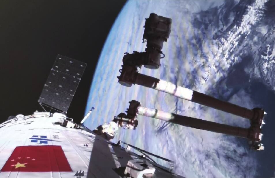 Qiu Xin’an et al., Chinese Journal of Space Science 44(5):939 (2024) [3]; CC BY 4.0.
The problem
Section titled “The problem”A station manipulator has to move modules and visiting vehicles of tens of tonnes, support crew on extravehicular activity, and inspect and maintain exterior equipment, all from a base that is itself a moving structure [1], [40]. The load range is wide: the Chinese core arm is rated for 25,000 kg and moves at 0.02 m/s loaded, while the same machine moves at 0.3 m/s unloaded [1], [2]. The environment removes the support that terrestrial arms take for granted. Most large space manipulators cannot lift themselves in 1 g, so full-system ground verification is not possible and each substitute (suspension, air bearing support, neutral buoyancy, hardware in the loop) removes some dynamics and keeps others [1]. The arm also has to reach hardware spread over the whole station exterior. The design answer for the seven-joint class is a symmetric chain with an end effector at each end, so that the arm can walk across target adapters on the hull instead of relying on a fixed base [1], [40].
What has flown
Section titled “What has flown”The Chinese Space Station Remote Manipulator System is a pair of seven-joint arms on the Tiangong station. Both are of the SSRMS configuration: three rotational joints at the shoulder, one at the elbow and three at the wrist, with link offsets at shoulder and wrist [5]. The two can be joined end to end into a single fourteen-degree-of-freedom chain [3], [41].
The core module manipulator launched with the Tianhe module on 29 April 2021 [3], [40]. Its developers describe it as the first large space robotic system developed independently in China for engineering application [3]. Published figures for it are a 10.2 m deployed length, 738 kg mass, 25 t payload and 0.6 m/s maximum tip speed, all as agency statements with no stated measurement basis [40]. Tasks performed with the operating subsystem to 2024 comprise extravehicular crew support, relocation identification runs, exterior inspection and the transposition of a cargo spacecraft [3].
The first large-payload operation was the Tianzhou-2 transposition test on 6 January 2022 [39]. The arm unlocked and separated the docked cargo craft from Tianhe, moved it to a predetermined position, reversed the sequence and returned it for re-docking and locking, in 47 minutes from a 06:12 Beijing time start [39]. The China Manned Space Agency called it the first time the arm had operated a large spacecraft in orbit. The report gives no arm loading, accuracy or re-docking alignment data [39].
The experiment module manipulator launched with Wentian on 24 July 2022 and is the shorter arm, 5 m deployed and rated for 3,000 kg, used for finer work on exposed payloads [2], [40]. Its end effector carries a six-axis force/torque sensor machined from Ti-6Al-4V, with acquisition electronics inside a 4 mm titanium housing and a heater circuit for thermal control [4]. Operating and survival temperature ranges are not published [4].
Both arms are commanded through the space manipulator operating subsystem in the core module, which combines Ethernet, MIL-STD-1553B and RS-422 buses [3], [1]. The console controller is a dual-computer cold standby pair, and bus controller authority switches between buses to shorten the control loop when the large arm works at radius [3]. The arms accept automated command sequences and manual rate control, and the operating subsystem defaults to ground control [1]. Its modes are ground operation (console forwarding data only), on-orbit operation by the crew, and simulation operation, in which commands drive a virtual platform instead of the arm [3]. The crew console uses force-feedback hand controllers built on a modified delta parallel mechanism, with a haptic rendering model that sums repulsive, situation-awareness, viscous and restoring force terms [3].
Relocation is the mobility mechanism. With the free end effector engaged on a target adapter, the base end effector releases and the arm walks end over end, described by CNSA as inchworm-like [40], [41]. The base is a software state: the console identifies the fixed end from the online status of the remote terminals on the bus [3]. The experiment arm can also work from the tip of the core arm, extending reach past 15 m [1].
What is being tried now
Section titled “What is being tried now”None of the approaches below has a published on-orbit result on the Chinese arms. The status of each is stated per family.
Inverse kinematics for the offset seven-joint arm. The shoulder and wrist offsets destabilize Denavit-Hartenberg solutions, and the redundancy gives infinitely many solutions [5], [6]. A 2026 treatment of the Wentian arm fixes one joint angle: closed form when joints 1 and 7 or 2 and 6 are fixed, numerical when 3, 4 or 5 are fixed. In simulation it solved 99.79 percent of 10,000 sampled poses at a 1e-4 threshold in about 1.1 ms, against 85.44 percent and 499.1 ms for a plain Jacobian baseline [5]. An alignment-constraint solution for the same arm type was tested separately [6]. The two success rates use different baselines and thresholds and are not comparable [5]. Status: simulation only.
Operator interface and teleoperation under delay. The flown interface is the haptic console above [3]. Learning-based planning for delayed teleoperation is a proposal: a Soft Actor-Critic planner with state augmentation held a 0.94 task success rate at a delay of one simulation step on a free-floating base with a rotating target, where a mapping method fell to 0.41 at four steps [35]. The environment is MuJoCo with the authors’ own arm model [35]. Status: simulation only.
Visual servoing for capture and approach. A 2024 survey classifies position-based, image-based and hybrid visual servoing for servicing arms and finds most validation in simulation or laboratory setups, with a few runs on the CSA testbed [34]. The CSSRMS adapter-based capture is cooperative and does not require this class of method [41]. Status: laboratory and simulation for non-cooperative targets.
Uncertainty-aware goal selection. NASA Langley propagates joint covariance through the Jacobian and rejects goal states whose 99 percent ellipsoid is not enclosed in the capture envelope [38]. The case shown is a commercial arm with encoder error only, in a ground demonstration with no flight data [38]. Status: ground.
Learning and AI-enabled operations. A 2026 survey of 52 studies organizes simulation environments, datasets, planning and onboard deployment for space robots, and reports no first-party measurements [33]. A review of space autonomy states that spacecraft remain largely reliant on ground-in-the-loop planning with pre-scripted sequences [25]. Status: proposals and simulation.
Ground emulation of microgravity. Air-bearing floors give two translations and one rotation: the ESA ORBIT floor, and NASA floors of 21.3 by 29.9 m at Johnson and 13.4 by 26.2 m at Marshall [2]. Hardware-in-the-loop facilities pair a dynamics simulation with industrial arms; one 2023 facility reported only qualitative tracking deviation and had its 6 m rail still in procurement [36]. A 2026 underwater method time-scales a mission plan so a BlueROV2 shares the disturbance robustness degree of the space plan, shown on one run per mission [37]. The CSSRMS operating subsystem was verified through hardware-in-the-loop simulation, desktop soft-connection testing, a two-dimensional air-bearing table and a three-dimensional suspension platform [3]. Status: ground test.
The numbers
Section titled “The numbers”Values marked CMM are the core module manipulator, EMM the experiment module manipulator.
| Parameter | CMM | EMM | Source |
|---|---|---|---|
| Degrees of freedom | 7 | 7 | [2], [5] |
| Joint layout | 3 shoulder, 1 elbow, 3 wrist | 3 shoulder, 1 elbow, 3 wrist | [5] |
| Deployed length | 10.2 m | 5 m | [40] |
| Mass | 738 kg | not published | [40] |
| Rated payload | 25,000 kg | 3,000 kg | [2] |
| Tip position accuracy | 45 mm | 10 mm | [2] |
| Tip orientation accuracy | 1 degree | 1 degree | [2] |
| Tip linear velocity, unloaded | 0.3 m/s | 0.2 m/s | [1], [2] |
| Tip linear velocity, loaded | 0.02 m/s | 0.03 m/s | [1], [2] |
| Tip angular velocity, unloaded | 3 deg/s | 3 deg/s | [1] |
| Tip angular velocity, loaded | 0.15 deg/s | 0.15 deg/s | [1] |
| Six-axis force/torque sensors | 2 | 2 | [4] |
| Combined chain reach | over 15 m | [1] | |
| Combined chain degrees of freedom | 14 | [3] |
CNSA gives 0.6 m/s as the maximum linear speed of the core arm [40]; the 0.3 m/s unloaded value in the table is the one tabulated in the reviewed literature [2].
EMM link dimensions, base to tip, in millimeters [5]:
| Member | Length |
|---|---|
| Base to shoulder | 716.1 |
| Shoulder offsets | 430, 430 |
| Lower boom | 2080 |
| Elbow offset | 387 |
| Upper boom | 2080 |
| Wrist offsets | 430, 430 |
| Wrist to tip | 716.1 |
| Event | Date | Source |
|---|---|---|
| Launch of CMM with Tianhe | 2021-04-29 | [3] |
| Tianzhou-2 transposition test, 47 minutes | 2022-01-06 | [39] |
| Launch of EMM with Wentian | 2022-07-24 | [2] |
Inverse kinematics comparison on the Wentian arm, 10,000 simulated poses [5]:
| Method | Success rate | Mean solve time |
|---|---|---|
| Fixed joint angle decoupling | 99.79 percent | 1.1 ms |
| Plain Jacobian iteration | 85.44 percent | 499.1 ms |
What is not established
Section titled “What is not established”Capability numbers come from two reviews [1], [2] and from Chinese government pages [40], [41]. The agency figures carry no test basis, and the reviews disagree with the agency on core arm length, 10.5 m [1] against 10.2 m [40]. Primary engineering papers exist only for the operating subsystem [3], the end effector force sensor [4] and the kinematics of the small arm [5], [6].
Joint-level design, actuator specification, structural material, power draw, thermal ranges and the end effector capture envelope are not published in any source obtained. The kinematics results are simulation only; the Wentian solver is conditional rather than a general closed form for the seven-joint system, and its baseline is a weak Jacobian iteration [5]. The Tianzhou-2 report gives duration but no loading, accuracy or alignment [39]. No equivalent of the contact-force accommodation results published for Western station arms exists for the Chinese arms, although the force/torque sensors supply the needed measurement [4]. No CSSRMS-specific measurement of base disturbance is published, and none of the ground emulation methods above has been reported as applied to the arms beyond the list in the operating-subsystem paper [3], [36].
References
- Papadopoulos, E., Aghili, F., Ma, O. and Lampariello, R. (2021). Robotic Manipulation and Capture in Space: A Survey
. Frontiers in Robotics and AI. Source
BibTeX
@article{papadopoulos2021robotic, title = {Robotic Manipulation and Capture in Space: A Survey}, author = {Papadopoulos, Evangelos and Aghili, Farhad and Ma, Ou and Lampariello, Roberto}, journal = {Frontiers in Robotics and AI}, volume = {8}, pages = {686723}, year = {2021}, doi = {10.3389/frobt.2021.686723}, abstract = {Space exploration and exploitation depend on the development of on-orbit robotic capabilities for tasks such as servicing of satellites, removing of orbital debris, or construction and maintenance of orbital assets. Manipulation and capture of objects on-orbit are key enablers for these capabilities. This survey addresses fundamental aspects of manipulation and capture, such as the dynamics of space manipulator systems (SMS), i.e., satellites equipped with manipulators, the contact dynamics between manipulator grippers/payloads and targets, and the methods for identifying properties of SMSs and their targets. Also, it presents recent work of sensing pose and system states, of motion planning for capturing a target, and of feedback control methods for SMS during motion or interaction tasks. Finally, the paper reviews major ground testing testbeds for capture operations, and several notable missions and technologies developed for capture of targets on-orbit.} } - Alizadeh, A. and Zhu, Z. H. (2024). A comprehensive survey of space robotic manipulators for on-orbit servicing
. Frontiers in Robotics and AI. Source
BibTeX
@article{alizadeh2024comprehensive, title = {A comprehensive survey of space robotic manipulators for on-orbit servicing}, author = {Alizadeh, Ali and Zhu, Zheng H.}, journal = {Frontiers in Robotics and AI}, volume = {11}, pages = {1470950}, year = {2024}, doi = {10.3389/frobt.2024.1470950}, abstract = {On-Orbit Servicing (OOS) robots are transforming space exploration by enabling vital maintenance and repair of spacecraft directly in space. However, achieving precise and safe manipulation in microgravity necessitates overcoming significant challenges. This survey delves into four crucial areas essential for successful OOS manipulation: object state estimation, motion planning, and feedback control. Techniques from traditional vision to advanced X-ray and neural network methods are explored for object state estimation. Strategies for fuel-optimized trajectories, docking maneuvers, and collision avoidance are examined in motion planning. The survey also explores control methods for various scenarios, including cooperative manipulation and handling uncertainties, in feedback control. Additionally, this survey examines how Machine learning techniques can further propel OOS robots towards more complex and delicate tasks in space.} } - Qiu, X., Ma, D., Tian, L., Hu, Y., Wu, Z., Zeng, Z., Wei, Z., Duan, F., Xiao, Q., Ma, H. and Shi, W. (2024). Design and Implementation of Space Manipulator Operating Subsystem
. Chinese Journal of Space Science, 5. Source
BibTeX
@article{qiu2024design, title = {Design and Implementation of Space Manipulator Operating Subsystem}, author = {Qiu, Xin'an and Ma, Dongtao and Tian, Licheng and Hu, Yuqian and Wu, Zhihong and Zeng, Zhenglin and Wei, Zhiming and Duan, Fuwei and Xiao, Qiang and Ma, Hongjiong and Shi, Wei}, journal = {Chinese Journal of Space Science}, volume = {44}, number = {5}, pages = {939--947}, year = {2024}, doi = {10.11728/cjss2024.05.2023-0081}, abstract = {As an important platform for the construction and on-orbit operation of space station, the space manipulator operating subsystem is the first independently developed large-scale space robotic system for aerospace engineering applications in China. The space robot arm has 14 degrees of freedom under the combination of the two arms, with large motion inertia, high operating precision, and support for multi-mode work. In this paper, according to the characteristics of space manipulator on-orbit mission, a space manipulator operation subsystem is established, which is supporting long-term on-orbit and multi-mode operation. The operation subsystem is composed of manipulator console, virtual simulation platform and display, which can meet the requirements of multitasking. This paper provides a summarize overview of the architecture, working mode, and technical characteristics of the operation subsystem, and focuses on analyzing the system bus structure, multimodal human-computer interaction technology, and force perception rendering algorithms of the operation subsystem. According to the ground test and on-orbit work, the verification of space manipulator operation subsystem is obtained, which provides valuable experience and data for space manipulator operation mission. The results show that the space manipulator operating subsystem can better carry out on-orbit management of the space robotic arm, monitor the whole process of it, as well as ground and on-orbit remote control and manipulation; the application of force perception rendering technology can better support the fine manipulation of the space robotic arm end and joints; the virtual simulation platform can effectively simulate the on-orbit tasks of the space robotic arm and simulate the pre-task rehearsal and training of the support task. The space manipulator operating subsystem has accumulated experience and data to support space robotic arm mission implementation.} } - Sun, Y. (2022). Design, Manufacture, Test and Experiment of Six-Axis Force Torque Sensor for Chinese Experimental Module Manipulator
. Sensors, 9. Source
BibTeX
@article{sun2022design, title = {Design, Manufacture, Test and Experiment of Six-Axis Force Torque Sensor for Chinese Experimental Module Manipulator}, author = {Sun, Yongjun}, journal = {Sensors}, volume = {22}, number = {9}, pages = {3603}, year = {2022}, doi = {10.3390/s22093603}, abstract = {A novel six-axis force/torque sensor (F/T sensor) for an Experimental Module Manipulator (EMM) in the Chinese Space Station (CSS) is developed in this paper. First, we designed the elastomer structure of the F/T sensor and used the analytical method and the finite element method to analyze the strain, in order to accomplish the strain gauges’ layout. Then, the electrical system was designed, which mainly realizes the acquisition of force/torque information, temperature and serial communication with the end effector (EE). Following this, we analyzed and designed the adaptability of the F/T sensor to the space environment. After this, the manufacturing process of the sensor was introduced in detail, and the F/T sensor was calibrated by a pulley weight system. Finally, the sensor was tested on the space environment adaptability of mechanical vibration and thermal vacuum on the ground. The test results show that the developed sensor has the ability to accurately measure three-dimensional force and three-dimensional moment information on orbit, which provides necessary conditions for the on-orbit fine operation of EMM.} } - Liu, Y., Gao, H., Zhao, Y., Zhang, S., Xie, Y., Yang, Y., Zhang, Y., Li, M., Jiang, Z. and Xie, Z. (2026). Inverse Kinematics of China Space Station Experimental Module Manipulator
. Machines, 3. Source
BibTeX
@article{liu2026inverse, title = {Inverse Kinematics of China Space Station Experimental Module Manipulator}, author = {Liu, Yang and Gao, Haibo and Zhao, Yuxiang and Zhang, Shuo and Xie, Yuteng and Yang, Yifan and Zhang, Yonglong and Li, Mengfei and Jiang, Zhiduo and Xie, Zongwu}, journal = {Machines}, volume = {14}, number = {3}, pages = {284}, year = {2026}, doi = {10.3390/machines14030284}, abstract = {SSRMS refers to a Space Station Remote Manipulator System. The robotic arm of the Wentian module can complete tasks such as supporting astronauts’ extravehicular activities, installing and maintaining payloads, and inspecting the space station. The seven-joint SSRMS manipulator is critical for space missions. This study aims to build its kinematic model via screw theory. It simplifies SSRMS to right-angle rods, defines joint screw axes, twist coordinates, and initial pose matrix. Using the PoE (Product of Exponentials) formula, the 7-DOF forward kinematics equation is derived. In addition, it derives fixed joint angle for inverse kinematics, including analytical solutions and numerical solutions. It elaborates analytical solutions for fixing joints 1/7 and 2/6 and numerical solutions for fixing joints 3/4/5, solves all joint angles via kinematic decoupling, and addresses special cases. Experiments with China’s space station small arm parameters show the probability of meeting the accuracy threshold 10−4 is 99.79%, verifying model effectiveness, while noting singularity-related weak solving areas. This provides a reliable basis for subsequent inverse kinematics optimization.} } - Qin, L., Wei, X., Lv, L., Han, L. and Fang, G. (2023). An Analytical Solution for Inverse Kinematics of SSRMS-Type Redundant Manipulators
. Sensors, 12. Source
BibTeX
@article{qin2023analytical, title = {An Analytical Solution for Inverse Kinematics of SSRMS-Type Redundant Manipulators}, author = {Qin, Li and Wei, Xiao and Lv, Liangliang and Han, Liangliang and Fang, Guangqiang}, journal = {Sensors}, volume = {23}, number = {12}, pages = {5412}, year = {2023}, doi = {10.3390/s23125412}, abstract = {Compared with non-redundant manipulators, the self-motion of 7-DOF redundant manipulators results in an infinite number of inverse kinematics solutions for a desired end-effector pose. This paper proposes an efficient and accurate analytical solution for inverse kinematics of SSRMS-type redundant manipulators. This solution is applicable to SRS-type manipulators with the same configuration. The proposed method involves introducing an alignment constraint to restrain the self-motion and to decompose the spatial inverse kinematics problem into three independent planar subproblems simultaneously. The resulting geometric equations depend on the part of the joint angles, respectively. These equations are then computed recursively and efficiently using the sequences of (θ1,θ7), (θ2,θ6), and (θ3,θ4,θ5), generating up to sixteen sets of solutions for a given desired end-effector pose. Additionally, two complementary methods are proposed for overcoming the possible singular configuration and judging unsolvable poses. Finally, numerical simulations are conducted to investigate the performance of the proposed approach in terms of average calculation time, success rate, average position error, and the ability to plan a trajectory with singular configurations.} } - Gao, Y. and Chien, S. (2021). Autonomy for Space Robots: Past, Present, and Future
. Current Robotics Reports. Source
BibTeX
@article{gao2021autonomy, title = {Autonomy for Space Robots: Past, Present, and Future}, author = {Gao, Yang and Chien, Steve}, journal = {Current Robotics Reports}, volume = {2}, pages = {251--263}, year = {2021}, doi = {10.1007/s43154-021-00057-2}, abstract = {Abstract Purpose of Review The purpose of this review is to highlight space autonomy advances across mission phases, capture the anticipated need for autonomy and associated rationale, assess state of the practice, and share thoughts for future advancements that could lead to a new frontier in space exploration. Recent Findings Over the past two decades, several autonomous functions and system-level capabilities have been demonstrated and used in spacecraft operations. In spite of that, spacecraft today remain largely reliant on ground in the loop to assess situations and plan next actions, using pre-scripted command sequences. Advances have been made across mission phases including spacecraft navigation; proximity operations; entry, descent, and landing; surface mobility and manipulation; and data handling. But past successful practices may not be sustainable for future exploration. The ability of ground operators to predict the outcome of their plans seriously diminishes when platforms physically interact with planetary bodies, as has been experienced in two decades of Mars surface operations. This results from uncertainties that arise due to limited knowledge, complex physical interaction with the environment, and limitations of associated models. Summary Robotics and autonomy are synergistic, wherein robotics provides flexibility, autonomy exercises it to more effectively and robustly explore unknown worlds. Such capabilities can be substantially advanced by leveraging the rapid growth in SmallSats, the relative accessibility of near-Earth objects, and the recent increase in launch opportunities.} } - Huang, Z., Chen, G., Hao, Z., Tang, G., Zong, J., Ban, G., Wang, J., Lv, H., Ren, C. and Liu, S. (2026). Artificial Intelligence-Enabled Space Robot Operations: Technologies, Challenges and Prospects. arxiv.org/abs/2609.16880
BibTeX
@misc{huang2026artificial, title = {Artificial Intelligence-Enabled Space Robot Operations: Technologies, Challenges and Prospects}, author = {Huang, Zeyuan and Chen, Gang and Hao, Zixuan and Tang, Guoqin and Zong, Junyi and Ban, Guoyou and Wang, Jiale and Lv, Haoyang and Ren, Chaoqian and Liu, Sitong}, year = {2026}, url = {https://arxiv.org/abs/2609.16880} } - Amaya-Mejía, L. M., Ghita, M., Dentler, J., Olivares-Mendez, M. and Martinez, C. (2024). Visual Servoing for Robotic On-Orbit Servicing: A Survey
. International Conference on Space Robotics. Source
BibTeX
@inproceedings{amayamejia2024bvisual, title = {Visual Servoing for Robotic On-Orbit Servicing: A Survey}, author = {Amaya-Mejía, Lina María and Ghita, Mohamed and Dentler, Jan and Olivares-Mendez, Miguel and Martinez, Carol}, booktitle = {International Conference on Space Robotics}, year = {2024}, url = {https://arxiv.org/abs/2409.02324v1} } - 山下, 博., Tian, X., Yuan, B., Li, Z., Liang, B. and Wang, X. (2024). Trajectory Planning for Teleoperated Space Manipulators Using Deep Reinforcement Learning
. arXiv. Source
BibTeX
@article{shanxia2024trajectory, title = {Trajectory Planning for Teleoperated Space Manipulators Using Deep Reinforcement Learning}, author = {山下, 博 and Tian, Xianru and Yuan, Bo and Li, Zhiheng and Liang, Bin and Wang, Xueqian}, journal = {arXiv}, year = {2024}, doi = {10.48550/arxiv.2408.05460}, abstract = {Trajectory planning for teleoperated space manipulators involves challenges such as accurately modeling system dynamics, particularly in free-floating modes with non-holonomic constraints, and managing time delays that increase model uncertainty and affect control precision. Traditional teleoperation methods rely on precise dynamic models requiring complex parameter identification and calibration, while data-driven methods do not require prior knowledge but struggle with time delays. A novel framework utilizing deep reinforcement learning (DRL) is introduced to address these challenges. The framework incorporates three methods: Mapping, Prediction, and State Augmentation, to handle delays when delayed state information is received at the master end. The Soft Actor Critic (SAC) algorithm processes the state information to compute the next action, which is then sent to the remote manipulator for environmental interaction. Four environments are constructed using the MuJoCo simulation platform to account for variations in base and target fixation: fixed base and target, fixed base with rotated target, free-floating base with fixed target, and free-floating base with rotated target. Extensive experiments with both constant and random delays are conducted to evaluate the proposed methods. Results demonstrate that all three methods effectively address trajectory planning challenges, with State Augmentation showing superior efficiency and robustness.} } - Sah, R., Srivastava, R. and Das, K. (2023). Development of On-Ground Hardware In Loop Simulation Facility for Space Robotics. Source
BibTeX
@article{sah2023development, title = {Development of On-Ground Hardware In Loop Simulation Facility for Space Robotics}, author = {Sah, Roshan and Srivastava, Raunak and Das, Kaushik}, year = {2023}, url = {https://arxiv.org/abs/2306.03785v1} } - Verhagen, J., Krantz, E., Sidrane, C., Dörner, D., De Carli, N., Roque, P., Mao, H., Tibert, G., Stenius, I., Fuglesang, C., Dimarogonas, D. and Tumova, J. (2026). Validation of Space Robotics in Underwater Environments via Disturbance Robustness Equivalency
. IEEE International Conference on Robotics and Automation. Source
BibTeX
@inproceedings{verhagen2026validation, title = {Validation of Space Robotics in Underwater Environments via Disturbance Robustness Equivalency}, author = {Verhagen, Joris and Krantz, Elias and Sidrane, Chelsea and Dörner, David and De Carli, Nicola and Roque, Pedro and Mao, Huina and Tibert, Gunnar and Stenius, Ivan and Fuglesang, Christer and Dimarogonas, Dimos and Tumova, Jana}, booktitle = {IEEE International Conference on Robotics and Automation}, pages = {5327-5334}, year = {2026}, doi = {10.1109/icra57385.2026.11697381} } - Cooper, J. R., Bacher, D. L. and Moser, J. N. (2023). Uncertainty in Servicing and Assembly Tasks for Space Robotic Manipulators
. IEEE Space Mission Challenges for Information Technology - IEEE Space Computing Conference. Source
BibTeX
@inproceedings{cooper2023uncertainty, title = {Uncertainty in Servicing and Assembly Tasks for Space Robotic Manipulators}, author = {Cooper, John R and Bacher, David L and Moser, Joshua N}, booktitle = {IEEE Space Mission Challenges for Information Technology - IEEE Space Computing Conference}, year = {2023}, url = {https://ntrs.nasa.gov/citations/20230010075}, abstract = {This presentation will discuss a subset of the sources of uncertainty that impact autonomous in-space servicing, assembly, and manufacturing missions. These include robotic manipulator modeling uncertainties in both kinematics and dynamics, perception error associated machine learning models for pose estimation, and sensor noise. Mitigation strategies will be discussed including the incorporation of capture envelopes in the design of robotic tools and selection of robot goal poses to minimize end-effector sensitivity in manipulators with redundant degrees of freedom.} } - China Manned Space Agency. (2022). China completes in-orbit spacecraft transposition test with space station's robotic arm. english.www.gov.cn/news/photos/202201/07/content_WS61d7908fc6d09c94e4...
BibTeX
@misc{china2022china, title = {China completes in-orbit spacecraft transposition test with space station's robotic arm}, author = {{China Manned Space Agency}}, year = {2022}, url = {https://english.www.gov.cn/news/photos/202201/07/content_WS61d7908fc6d09c94e48a3489.html} } - (2026). CNSA: The two robotic arms of the China Space Station. cnsa.gov.cn/n6758968/n6758973/c10388340/content.html
BibTeX
@misc{cnsatwo, title = {CNSA: The two robotic arms of the China Space Station}, organization = {cnsa.gov.cn}, year = {2026}, url = {https://www.cnsa.gov.cn/n6758968/n6758973/c10388340/content.html} } - (2026). SASTIND: What you should know about space station robotic arms. sastind.gov.cn/n10086205/n10086408/n10104265/c10460600/content.html
BibTeX
@misc{sastindwhat,
  title = {SASTIND: What you should know about space station robotic arms},
  organization = {sastind.gov.cn},
  year = {2026},
  url = {https://www.sastind.gov.cn/n10086205/n10086408/n10104265/c10460600/content.html}
}
Further reading
- Kumar, R. and Hayes, R. (1991). System requirements and design features of Space Station Remote Manipulator System mechanisms . Aerospace Mechanisms Symposium. Source
- Stieber, M. E., Hunter, D. G. and Abramovici, A. (1999). Overview of the Mobile Servicing System for the International Space Station . International Symposium on Artificial Intelligence, Robotics and Automation in Space. Source
- Daniell, R. G. and Sachdev, S. S. (1982). The Design and Development of an End Effector for the Shuttle Remote Manipulator System . Aerospace Mechanisms Symposium. Source
- Crane, C. D. I., Duffy, J. and Carnahan, T. (1991). A kinematic analysis of the Space Station remote manipulator system (SSRMS) . Journal of Robotic Systems. Source
- Taylor, E. C. and Ross, M. (1989). A Comparison of the Shuttle Remote Manipulator System and the Space Station Freedom Mobile Servicing Center . NASA. Source
- Mukherji, R., Rey, D. A., Stieber, M. and Lymer, J. (2001). Special Purpose Dexterous Manipulator (SPDM) Advanced Control Features and Development Test Results . International Symposium on Artificial Intelligence, Robotics and Automation in Space. Source
- (2026). CSA: Comparative table of Canadarm, Canadarm2 and Canadarm3. asc-csa.gc.ca/eng/iss/canadarm2/canadarm-canadarm2-canadarm3-comparat...
- (2026). CSA: Canadarm2. asc-csa.gc.ca/eng/iss/canadarm2
- (2026). JAXA: Remote Manipulator System, About Kibo. iss.jaxa.jp/en/kibo/about/kibo/rms
- Matsueda, T., Kuwao, F., Motohashi, S. and Okamura, R. (1994). Development of Japanese Experiment Module Remote Manipulator System . International Symposium on Artificial Intelligence, Robotics and Automation in Space. Source
- European Space Agency. (2021). European Robotic Arm: The International Space Station's Latest Upgrade . ESA Human and Robotic Exploration. Source
- Baker, F. C., Favre, E., Mozzon, J.-M., Crausaz, A. and Juriens, P. (1999). European Robotic Arm (ERA) Manipulator Joint System Motor Unit and Tribological Brake . European Space Mechanisms and Tribology Symposium. Source
- Kolvenbach, H. and Wormnes, K. (2016). Recent Developments on ORBIT, a 3-DoF Free Floating Contact Dynamics Testbed . International Symposium on Artificial Intelligence, Robotics and Automation in Space. Source
- (2026). ESA: Orbital Robotics Laboratory. esa.int/Education/ESA_Academy_Experiments_programme/Orbital_Robotics_Lab
- Okamoto, O., Nakaya, T. and Pokines, B. (1994). Concept verification of three dimensional free motion simulator for space robot . Workshop for Computational Fluid Dynamic Applications in Rocket Propulsion. Source
- Artigas, J., Riecke, C., Weber, B., Stelzer, M., Balachandran, R., Schaetzle, S., Bayer, R., Steinmetz, B.-M., Vogel, J., Brunner, B., Albu-Schäffer, A., Guk, M., Zaborovskyi, V., Kondratiev, A., Muliukha, V., Silinenko, A. and Shmakov, O. (2016). Force-Feedback Teleoperation of On-Ground Robots from the International Space Station in the Frame of the KONTUR-2 Experiment . International Symposium on Artificial Intelligence, Robotics and Automation in Space. Source
- Jules, K., McPherson, K., Hrovat, K. and Kelly, E. (2004). Initial characterization of the microgravity environment of the international space station: increments 2 through 4 . Acta Astronautica. Source
- DeLombard, R., McPherson, K., Hrovat, K., Moskowitz, M., Rogers, M. J. B. and Reckart, T. (1997). Microgravity Environment Description Handbook . NASA. Source
- Mulvaney, J., Arney, D., Williams, C., Morel, J., Stockdale, C., Whitlock, C. and Balaji, V. (2025). In-Space Servicing, Assembly, and Manufacturing (ISAM) State of Play, 2025 Edition . NASA. Source
- Nenchev, D. N., Yoshida, K., Vichitkulsawat, P. and Uchiyama, M. (1999). Reaction Null-Space Control of Flexible Structure Mounted Manipulator Systems . IEEE Transactions on Robotics and Automation. Source
- Papadopoulos, L. and Tolson, R. H. (1993). Admittance Model for the Shuttle Remote Manipulator System in Four Configurations. Source
- Carroll, T. W. (1987). The design and development of a mobile transporter system for the Space Station Remote Manipulator System . NASA. Source
- Lippay, A. L. (1977). Multi-Axis Hand Controller for the Shuttle Remote Manipulator System . The Annual Conference on Manual Control. Source
- Ehrenstrom, W. A., Forrester, P. and Swaney, C. (1994). International Space Station Alpha Remote Manipulator System Workstation Controls Test Report . NASA Johnson Space Center. Source
- Bassett, D. A. and Abramovici, A. (1999). Special Purpose Dexterous Manipulator (SPDM) Requirements Verification . International Symposium on Artificial Intelligence, Robotics and Automation in Space. Source