JAXA Space Exploration Innovation Hub Center Space Exploration Experiment Building
JAXA Space Exploration Innovation Hub Center.
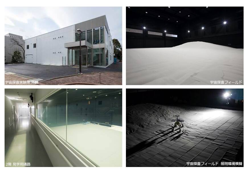
A rover or lander cannot be qualified against the Moon itself, so an agency decides which parts of the lunar environment to build indoors and which to give up. Facilities converged on a split: a large dry terrain field for mobility and operations, separate chambers for vacuum, thermal and dust, separate rigs for gravity offload, and separate buildings for vibration and shock. NASA Glenn lists distinct facilities for these functions rather than one hall that does all of them [13]. The Sagamihara field follows the same split. It is a 400 m2 indoor sand field with controlled lighting and climate in which full-size rovers and landers are driven, dropped and operated [1], and it provides repeatable terrain and illumination only. It occupies the Space Exploration Experiment Building, run by the Space Exploration Innovation Hub Center. JAXA publishes the building and the field only in Japanese, as 宇宙探査実験棟 and 宇宙探査フィールド, so both English names are translations [1][2]. The building was completed in February 2017 and entered service in May 2017 [2]. It sits beside the older ISAS Sagamihara test buildings, which provide the structural, vibration, anechoic and drop-test capability the field does not attempt [3].
Approaches to lunar surface ground testing
Section titled “Approaches to lunar surface ground testing”Indoor terrain fields trade environment for repeatability and scale. Sagamihara is one; the ESTEC Mars Yard is an 8 by 8 m indoor bed of sand, gravel and rocks with a crater, boulder field, dune and gravel slope, tracked by infrared cameras, used to assess locomotion, navigation and arm placement together [28]. The NASA Kennedy IPEx autonomy test site is a 39.6 by 21.3 m light-tight tent with six 1400 W stadium lights standing in for the low polar sun, a mock lander and OptiTrack ground truth, and hosted a five-day TRL 5 excavation demonstration in August 2024 [17]. Swamp Works at Kennedy built Big Bin, a 626 cubic foot containment chamber intended to hold 120 tons of regolith for full-scale robot testing [20]. A Colorado School of Mines lunar surface simulator was reported in 2025 as a new testbed for lunar machinery [19]. Verti-Arena is an 8 by 8 m reconfigurable indoor testbed with ten terrain types and eight-camera motion capture, but for 1/10-scale vehicles [26]. All of these run at ambient pressure and 1 g.
Instrumented soil bins and single-wheel rigs measure wheel-soil interaction rather than whole-vehicle behavior. DLR built a 5.5 by 10 by 0.5 m bin with a laser-beam elevation mapper and an infrared tracker for ExoMars wheel-soil model validation [14]. Its successor TROLL automates soil loosening, leveling, compaction and the run around a force-controlled industrial robot [15][16]. NASA’s consolidated best practice for rover and tire mobility testing covers full-vehicle drawbar pull, slope, cross-slope and obstacle tests and single-wheel tests, with lessons from VIPER [18].
Environment chambers add what a terrain field omits. The MSFC Lunar Environments Test System was a roughly 2.5 ft cryopumped chamber combining high vacuum, thermal extremes, vacuum ultraviolet and an electron flood gun over 75 kg of JSC-1a simulant, with some subsystems still in commissioning at the time of the source [21]. The Glenn Lunar Dust Adhesion Bell Jar was built around five factors a high fidelity simulation must reproduce: dust, vacuum, temperature, solar radiation and reduced gravity [27]. Glenn’s own facility index omits the Bell Jar [13].
Reduced gravity is reached by parabolic flight, drop tower or cable offload, each with a limit. Two Falcon 20 parabolic campaigns showed that reduced-weight testing at 1 g overstates lunar mobility, which is why 1 g field results need a correction [22]. A rotating annular soil trench was designed for aircraft use because it fits a smaller footprint than a linear bin [25]. A shear and compression cell was built to measure regolith strength during drop tower falls [29]. For crewed work, ARGOS gives three active translational degrees of freedom and removes the roughly 30 s task limit of parabolic flight [24], and its offload fidelity depends on pivot placement near the combined suit and human center of gravity, established over 14 subjects and 68 configurations [23].
Drop and impact rigs. The MER airbag program ran 52 drop tests in the NASA Plum Brook vacuum chamber at 4 torr [9] and qualified hardware to the resulting loads on an electrodynamic shaker [10]. NASA Langley’s Impact Dynamics Research Facility, converted from the Lunar Landing Research Facility, used a pendulum swing to reach flight path velocities up to about 27.0 m/s with flight path angle within 8 percent [12].
What has flown versus what has not: none of the ground facilities above is a flight system. Their value is correlation with flight data, as in the MSL slip-versus-slope campaign compared with the first 250 sols of Curiosity data [11]. For the Sagamihara field no such comparison is published.
Laboratory data
Section titled “Laboratory data”| Parameter | Value |
|---|---|
| Operator | JAXA Space Exploration Innovation Hub Center, [1][3] |
| Location | Sagamihara Campus, Kanagawa, Japan [3] |
| Commissioned | Building completed February 2017, operational May 2017 [2] |
| Type | Indoor analogue terrain field with controlled illumination and climate |
| Floor area | Gross floor area 1232.76 m2; building area 899.83 m2; field 400 m2 [1][2] |
| Capabilities | Field, control rooms, cleanroom |
| Simulant or terrain | Silica sand, 425 t: 410 t at 0.3 to 0.6 mm, 15 t at 3 to 5 mm |
| Instrumentation | Two control rooms, a catwalk, a 2.8 t indoor crane, xenon solar illumination |
| Ground truth | Not published. Users bring their own metrology |
| Fidelity limits | Ambient pressure, 1 g; silica sand, not a lunar simulant [1][7]. See below |
| Access | Open innovation and joint research with industry [1][2]. No lead time or fee published |
| Cited by | sora-q, lev-1 |
Capabilities
Section titled “Capabilities”Space Exploration Field
Section titled “Space Exploration Field”| Parameter | Value |
|---|---|
| Working volume | 22.6 x 17.7 m, 400 m2, ceiling height 10.5 m [1] |
| Test article limits | Handling by a 2.8 t indoor crane [1][2] |
| Vacuum | Not applicable. Ambient pressure |
| Temperature | Controlled, not cycled. No range or ramp rate published |
| Illumination | Darkroom with a single xenon solar source. No solar constant or collimation published |
| Simulant or terrain | Silica sand, 425 t, 0.3 to 0.6 mm and 3 to 5 mm, in flat, hill and gravel sections [1][2] |
| Slope | Piled by hand. 0 to 18 degrees used in a published campaign [5]. Maximum not published |
| Gravity offload | Not applicable |
| Instrumentation | Xenon solar illumination, catwalk, 2.8 t crane [1][2]. Users bring metrology |
The field is the center of the building and is described by JAXA as reproducing lunar surface terrain and illumination conditions so that exploration robots and landers can be evaluated under conditions close to real operation. The stated test types are surface driving, landing drop tests, flight tests and exploration work operation tests, run as a connected sequence rather than separately. JAXA attributes the field’s ability to take full-size landers and cooperative tests of several robots at once to its being among the largest in the world in both area and height.
Three design decisions define the envelope. The roof is a double folded insulated metal panel chosen to keep the interior temperature uniform against outside weather [2]. The ground under the field was improved into a strong bearing layer to support 425 tonnes of sand, and the floor was built uniform across its whole area so that terrain can be piled into a hill or dug out like a well at any point, and so that it withstands the impact of a lander touchdown test. Temperature and humidity are managed so that the sand state and the lighting are identical from run to run [1]. No relative density target or preparation procedure between runs is published, and no solar constant fraction, collimation angle or achievable solar elevation is published for the xenon illumination.
Operations control rooms
Section titled “Operations control rooms”| Parameter | Value |
|---|---|
| Working volume | Two rooms adjoining the field and overlooking it [1][2] |
| Instrumentation | Laid out to simulate a three-point relay chain [2] |
The two control rooms are laid out to stand in for a three-node relay, such as ground station, spacecraft interior and surface, or Earth, Moon and rover, rather than for a single operator position [2]. That makes operations latency and relay topology a testable variable alongside the terrain.
The second-floor viewing corridor gives a full view of the field for public visitors, and uses instantly switchable glass that changes from frosted to clear. JAXA states the switch is not only theatrical: it protects the intellectual property embodied in the hardware under test by making the field invisible on demand.
Cleanroom
Section titled “Cleanroom”Adjacent to the field, the Innovation Hub operates an ISO Class 1 cleanroom at Sagamihara, built for planetary protection work: comparing the sterilization and decontamination effectiveness and corrosion behavior of different techniques, building decontamination systems able to break down spores and biomolecules, extending inactivation to viruses and allergens where prior knowledge was thin, and developing the verification methods for all of it [4]. That work sits inside a discipline that has been under continuous revision since the first NASA sterilization policies: bioburden reduction, remote bioassay laboratories and the microbial detection methods used to certify a spacecraft clean have all changed as mission categories and science objectives have grown more demanding [8]. The Sagamihara cleanroom’s decontamination and verification work is a contribution to that same open problem rather than a fixed, solved procedure.
Instrumentation
Section titled “Instrumentation”Facility-supplied instrumentation published for the field is limited to the control rooms, the catwalk, the crane and the xenon solar illumination [1]. Campaign-specific metrology is brought by users. In the Tohoku University EX1 campaign the rover was tracked by a 16-camera OptiTrack system at 180 Hz with plus or minus 0.15 mm accuracy, and external cameras independently timed wheel rotations across a 2 m section so that average slip could be estimated without relying on the rover [5]. The MSL traverse campaign used GPS and motion-capture ground truth for Mars-weight vehicles on analog terrain [11].
The neighboring ISAS buildings hold the environmental test capability the field does not: the Flight Environment Test Building carries the mechanical environment test room for vibration, shock and dynamic balance, plus a magnetic shield room, a space chamber, a radio anechoic chamber and a clean assembly room; the Structure and Mechanics Test Building tests strength and rigidity of structures and the function of interstage joints and fairings; and the Advanced Facility for Space Science and Technology holds wind tunnels, space plasma and cosmic radiation experiment facilities and a weightless drop test facility [3]. The source gives no envelope figure for any of them.
What it does not reproduce
Section titled “What it does not reproduce”JAXA claims that the sand state and illumination are the same on every run and unaffected by weather, through temperature and humidity control, a darkroom and artificial lighting [1]. Nothing in the published description offers vacuum, thermal cycling or reduced gravity in the field.
The soil is silica sand, 0.3 to 0.6 mm for most of the mass and 3 to 5 mm for the gravel section [1]. The Tohoku group describes dry loose silica sand of this class as a low-fidelity lunar regolith simulant [5]. NASA’s 2005 simulant workshop argued for common, characterized root and derivative simulants, in part because Apollo samples are too scarce for routine mechanical testing [6]. The current NASA user’s guide concludes that no single simulant is best and none reproduces every aspect of lunar regolith [7]. Bulk silica sand chosen for handling 425 t sits outside that framework.
Drop testing is bounded by the building. The floor was designed to withstand lander touchdown impact [2] and the 10.5 m ceiling bounds drop height [1]. The alternatives are dedicated rigs: the MER airbag tests [9][10] and the Langley pendulum gantry [12]. The Sagamihara trade is one uniform floor, which takes any article the 2.8 t crane can lift, against a rig tuned to one vehicle class.
The cleanroom is a separate function. The Innovation Hub operates an ISO Class 1 cleanroom for planetary protection work: comparing sterilization and decontamination methods for effectiveness and corrosion, extending inactivation to viruses and allergens, and developing verification methods [4]. Planetary protection implementation on Mars landed missions has been revised repeatedly, including after heat-resistant spores were found in assembly cleanrooms [8], and sample curation faced the same tension between containment and cleanliness from the Lunar Receiving Laboratory onward [31].
Campaigns run there
Section titled “Campaigns run there”Tohoku University EX1 high-speed rover. A four-wheeled 21.63 kg rover with passive spring-damper suspension was driven over a 20 m by 20 m area of silica sand about 0.3 m deep, at wheel speeds of 0.23 to 1.17 m/s on flat ground and slopes to 18 degrees, with acceleration and deceleration runs for transient slip [5]. The slip and sinkage regressions were fitted for a real-time lunar simulator. Slip must be computed against an effective radius that includes grouser height, or the rim radius alone gives spurious negative slip [5]. The reported 0.02 percent flat-terrain slip error compares the simulator with its own regression models, so it measures implementation fidelity, not physical accuracy [5]. The ESA Automation and Robotics Laboratories index lists comparable facilities at ESTEC for orbital, planetary and regolith work [30].
What is not established
Section titled “What is not established”JAXA’s publications give area, sand mass and completion date for the field, but no relative density target, no preparation procedure between runs, and no solar constant fraction, collimation angle or solar elevation range for the xenon source [1][2]. No bearing strength, allowable impact energy, drop height or floor load rating is stated [2]. The cleanroom page repeats the field’s specifications instead of giving cleanroom size or power figures, and its ISO Class 1 rating is asserted without certification detail [4]. No facility-side ground truth for slope, sinkage or slip is published; the one quantitative result, the EX1 regressions, comes from a visiting team’s instrumentation and was fitted at 1 g on a low-fidelity simulant [5]. Whether the sand has been benchmarked against a characterized simulant is not published [6][7]. Correlation of Sagamihara results with flight or reduced-gravity data, as done for MSL and in parabolic flight [11][22], is not stated. Published campaign claims about specific missions tested in the building could not be verified from the held sources.
References
- (2026). JAXA Space Exploration Innovation Hub Center: Space Exploration Experiment Building. ihub-tansa.jaxa.jp/about/afse.html
BibTeX
@misc{jaxaafse, title = {JAXA Space Exploration Innovation Hub Center: Space Exploration Experiment Building}, organization = {ihub-tansa.jaxa.jp}, year = {2026}, url = {https://www.ihub-tansa.jaxa.jp/about/afse.html} } - (2026). JAXA Facilities Department: Space Exploration Experiment Building. stage.tksc.jaxa.jp/shisetsu/locations/sagamihara/exploration
BibTeX
@misc{jaxashisetsuafse, title = {JAXA Facilities Department: Space Exploration Experiment Building}, organization = {stage.tksc.jaxa.jp}, year = {2026}, url = {https://stage.tksc.jaxa.jp/shisetsu/locations/sagamihara/exploration/} } - (2026). ISAS: Sagamihara Campus Facilities. isas.jaxa.jp/en/about/facilities/sagamihara.html
BibTeX
@misc{isassagamihara, title = {ISAS: Sagamihara Campus Facilities}, organization = {isas.jaxa.jp}, year = {2026}, url = {https://www.isas.jaxa.jp/en/about/facilities/sagamihara.html} } - (2026). JAXA Space Exploration Innovation Hub Center: Cleanroom. ihub-tansa.jaxa.jp/about/cleanroom.html
BibTeX
@misc{jaxaihubcleanroom, title = {JAXA Space Exploration Innovation Hub Center: Cleanroom}, organization = {ihub-tansa.jaxa.jp}, year = {2026}, url = {https://www.ihub-tansa.jaxa.jp/about/cleanroom.html} } - Kern, J. M., Hurrell, J. M., Santra, S., Takehana, K., Uno, K. and Yoshida, K. (2025). Data-Driven Terramechanics Approach Towards a Realistic Real-Time Simulator for Lunar Rovers
. arXiv preprint. Source
BibTeX
@article{kern2026data, title = {Data-Driven Terramechanics Approach Towards a Realistic Real-Time Simulator for Lunar Rovers}, author = {Kern, Jakob M. and Hurrell, James M. and Santra, Shreya and Takehana, Keisuke and Uno, Kentaro and Yoshida, Kazuya}, journal = {arXiv preprint}, pages = {662-668}, year = {2025}, doi = {10.1109/isparo66239.2025.11436587}, abstract = {High-fidelity simulators for the lunar surface provide a digital environment for extensive testing of rover operations and mission planning. However, current simulators focus on either visual realism or physical accuracy, which limits their capability to replicate lunar conditions comprehensively. This work addresses that gap by combining high visual fidelity with realistic terrain interaction for a realistic representation of rovers on the lunar surface. Because direct simulation of wheel-soil interactions is computationally expensive, a data-driven approach was adopted, using regression models for slip and sinkage from data collected in both full-rover and single-wheel experiments and simulations. The resulting regression-based terramechanics model accurately reproduced steady-state and dynamic slip, as well as sinkage behavior, on flat terrain and slopes up to 20°, with validation against field test results. Additionally, improvements were made to enhance the realism of terrain deformation and wheel trace visualization. This method supports real-time applications that require physically plausible terrain response alongside high visual fidelity.} } - Sibille, L., Carpenter, P., Schlagheck, R. and French, R. A. (2006). Lunar Regolith Simulant Materials: Recommendations for Standardization, Production, and Usage
. NASA Marshall Space Flight Center, NASA/TP-2006-214605. Source
BibTeX
@techreport{sibille2006development, title = {Lunar Regolith Simulant Materials: Recommendations for Standardization, Production, and Usage}, author = {Sibille, Laurent and Carpenter, Paul and Schlagheck, R. and French, R. A.}, number = {NASA/TP-2006-214605}, institution = {NASA Marshall Space Flight Center}, type = {NASA Technical Publication}, year = {2006}, url = {https://ntrs.nasa.gov/citations/20060051776}, abstract = {Experience gained during the Apollo program demonstrated the need for extensive testing of surface systems in relevant environments, including regolith materials similar to those encountered on the lunar surface. As NASA embarks on a return to the Moon, it is clear that the current lunar sample inventory is not only insufficient to support lunar surface technology and system development, but its scientific value is too great to be consumed by destructive studies. Every effort must be made to utilize standard simulant materials, which will allow developers to reduce the cost, development, and operational risks to surface systems. The Lunar Regolith Simulant Materials Workshop held in Huntsville, AL, on January 24 26, 2005, identified the need for widely accepted standard reference lunar simulant materials to perform research and development of technologies required for lunar operations. The workshop also established a need for a common, traceable, and repeatable process regarding the standardization, characterization, and distribution of lunar simulants. This document presents recommendations for the standardization, production and usage of lunar regolith simulant materials.} } - Slabic, A., Gruener, J. E., Kovtun, R. N., Rickman, D. L., Sibille, L., Oravec, H. A., Edmunson, J. and Keprta, S. (2024). Lunar Regolith Simulant User's Guide, Revision A
. NASA, NASA/TM-20240011783. Source
BibTeX
@techreport{slabic2024lunar, title = {Lunar Regolith Simulant User's Guide, Revision A}, author = {Slabic, Ane and Gruener, John E. and Kovtun, Rostislav N. and Rickman, Douglas L. and Sibille, Laurent and Oravec, Heather A. and Edmunson, Jennifer and Keprta, Sean}, number = {NASA/TM-20240011783}, institution = {NASA}, year = {2024}, url = {https://ntrs.nasa.gov/citations/20240011783}, abstract = {This guide is titled Lunar Regolith Simulant User's Guide, Rev A, and two points need to be made about the title. First, is the use of the term "regolith". During the Apollo Program, the term "soil" was used for taking a sample of the loose material on the surface, and then cataloging that sample in the lunar curation database as a "soil sample". By the 1980s, the term "regolith" gained favor by lunar scientists. In the Lunar Sourcebook (Heiken et al., 1991), regolith is defined as "a general term for the layer or mantle of fragmental and unconsolidated rock material, whether residual or transported and of highly varied character, that nearly everywhere forms the surface of the land and overlies or covers bedrock". Regolith is a terrestrial term that seems to go back to 1897, according to a recent paper by Huggett (2023). Huggett summed up his paper by writing, "soil and regolith are one in the same". "Regolith" will mostly be used throughout this guide, as it tends to separate in one's mind the unique nature of the Moon's surface when compared to the inherent bias humans have in their mind when they hear and use the word "soil". When referring to Apollo samples, "soil" is used for historical context and in some places the simple term "lunar simulant" is also used. Secondly, Rev A is used in the title because NASA released its first Lunar Regolith Simulant User's Guide in 2010, near the end of NASA's Constellation Program (Schrader et al., 2010). This guide follows in the pattern of that first guide and will be updated on a periodic basis as new simulants are created, characterized and used, and as new information emerges about the Moon's regolith due to new lunar exploration missions, both robotic and human.} } - Kazarians, G. A., Benardini, J. N., Stricker, M. C., Schubert, W. W., Chen, F., Vaishampayan, P., Jones, M. A., Barengoltz, J. and Koukol, R. (2017). The Evolution of Planetary Protection Implementation on Mars Landed Missions
. IEEE Aerospace Conference. Source
BibTeX
@inproceedings{kazarians2017evoluation, title = {The Evolution of Planetary Protection Implementation on Mars Landed Missions}, author = {Kazarians, Gayane A. and Benardini, James N. and Stricker, Moogega C. and Schubert, Wayne W. and Chen, Fei and Vaishampayan, Parag and Jones, Melissa A. and Barengoltz, Jack and Koukol, Robert}, booktitle = {IEEE Aerospace Conference}, pages = {1-20}, publisher = {IEEE}, year = {2017}, doi = {10.1109/aero.2017.7943576}, abstract = {NASA has developed requirements dedicated to the prevention of forward and backward contamination during space exploration. Historically, international agreements provided guidelines to prevent contamination of the Moon and other celestial bodies, as well as the Earth (e.g., sample return missions). The UN Outer Space Treaty was established in 1967 and the Committee on Space Research (COSPAR) maintains a planetary protection policy complying with Article IX of this treaty. By avoiding forward contamination, the integrity of scientific exploration is preserved. Planetary Protection mission requirements are levied on missions to control contamination. These requirements are dependent on the science of the mission and on the celestial bodies encountered or targeted along the way. Consequently, categories are assigned to missions, and specific implementation plans are developed to meet the planetary protection requirements. NASA missions have evolved over time with increasingly more demanding scientific objectives and more complex flight systems to achieve those objectives and, thus, planetary protection methods and processes used for implementation have become much more intricate, complicated, and challenging. Here, we will portray the evolution of planetary protection implementation at JPL in several important areas throughout the course of NASA sponsored robotic Mars lander or rover missions, starting from Mars Pathfinder through the beginning of Mars 2020. Highlighted in the discussion will be process changes in planetary protection requirements development and flow down. Development and implementation of new and improved methods used in the reduction of spacecraft bioburden will be discussed as well as approaches and challenges that come along with setting up remote laboratories to perform bioassays. The consequences and forward planning of delays on missions will be highlighted as well as lessons learned on the impact of communication and training in achieving planetary protection requirements. The evolution of methods used for the detection of microbial bioburden on spacecraft hardware will be considered. These methods use standard microbiology as well as the adaptation of advances in biotechnology, molecular biology, and bioinformatics. Technical approaches developed for the prevention of contamination and recontamination of hardware during Assembly, Test, and Launch Operations will be discussed.} } - Adams, D. S. (2004). Mars Exploration Rover Airbag Landing Loads Testing and Analysis
. AIAA/ASME/ASCE/AHS/ASC Structures, Structural Dynamics, and Materials Conference. Source
BibTeX
@inproceedings{adams2004mars, title = {Mars Exploration Rover Airbag Landing Loads Testing and Analysis}, author = {Adams, Douglas S.}, booktitle = {AIAA/ASME/ASCE/AHS/ASC Structures, Structural Dynamics, and Materials Conference}, publisher = {American Institute of Aeronautics and Astronautics}, year = {2004}, doi = {10.2514/6.2004-1795}, abstract = {This paper presents a summary of the testing and analysis used to quantify the expected airbag landing loads for the Mars Exploration Rovers. The airbag drop test setup, lander instrumentation, and the test data reduction method are discussed in order to provide an understanding of the empirical loads. A set of limiting cases that bound the empirical data are developed for use in finite element modeling of the lander and rover models. A favorable comparison is made between the empirical data and available computational airbag models boosting confidence in the results.} } - Davis, G. L., Scharton, T. D. and Tsoi, W. B. (2002). Dynamic testing techniques for qualifying Mars Exploration Rover equipment to quasi-static landing loads
. IEEE Aerospace Conference. Source
BibTeX
@inproceedings{davis2002dynamic, title = {Dynamic testing techniques for qualifying Mars Exploration Rover equipment to quasi-static landing loads}, author = {Davis, G. L. and Scharton, Terry D. and Tsoi, W. B.}, booktitle = {IEEE Aerospace Conference}, publisher = {JPL Open Repository}, year = {2002}, url = {https://dataverse.jpl.nasa.gov/dataset.xhtml?persistentId=hdl:2014/8681} } - Heverly, M., Matthews, J., Lin, J., Fuller, D., Maimone, M., Biesiadecki, J. and Leichty, J. (2013). Traverse Performance Characterization for the Mars Science Laboratory Rover
. Journal of Field Robotics. Source
BibTeX
@article{heverly2013traverse, title = {Traverse Performance Characterization for the Mars Science Laboratory Rover}, author = {Heverly, Matt and Matthews, Jaret and Lin, Justin and Fuller, Dan and Maimone, Mark and Biesiadecki, Jeffrey and Leichty, John}, journal = {Journal of Field Robotics}, volume = {30}, pages = {835-846}, year = {2013}, doi = {10.1002/rob.21481}, abstract = {It is anticipated that the Mars Science Laboratory rover, named Curiosity, will traverse 10–20 km on the surface of Mars during its primary mission. In preparation for this traverse, Earth‐based tests were performed using Mars weight vehicles. These vehicles were driven over Mars analog bedrock, cohesive soil, and cohesionless sand at various slopes. Vehicle slip was characterized on each of these terrains versus slope for direct upslope driving. Results show that slopes up to 22 degrees are traversable on smooth bedrock and that slopes up to 28 degrees are traversable on some cohesive soils. In cohesionless sand, results show a sharp transition between moderate slip on 10 degree slopes and vehicle embedding at 17 degrees. For cohesionless sand, data are also presented showing the relationship between vehicle slip and wheel sinkage. Side by side testing of the Mars Exploration Rover test vehicle and the Mars Science Laboratory test vehicle show how increased wheel diameter leads to better slope climbing ability in sand for vehicles with nearly identical ground pressure. Lastly, preliminary data from Curiosity's initial driving on Mars are presented and compared to the Earth‐based testing, showing good agreement for the driving done during the first 250 Martian days.} } - Vaughan, V. L. J. and Alfaro-Bou, E. (1976). Impact dynamics research facility for full-scale aircraft crash testing
. NASA, NASA-TN-. Source
BibTeX
@techreport{vaughan1976impact, title = {Impact dynamics research facility for full-scale aircraft crash testing}, author = {Vaughan, V. L. J. and Alfaro-Bou, E.}, number = {NASA-TN-}, institution = {NASA}, year = {1976}, url = {https://ntrs.nasa.gov/citations/19760014085}, abstract = {An impact dynamics research facility (IDRF) was developed to crash test full-scale general aviation aircraft under free-flight test conditions. The aircraft are crashed into the impact surface as free bodies; a pendulum swing method is used to obtain desired flight paths and velocities. Flight paths up to -60 deg and aircraft velocities along the flight paths up to about 27.0 m/s can be obtained with a combination of swing-cable lengths and release heights made available by a large gantry. Seven twin engine, 2721-kg aircraft were successfully crash tested at the facility, and all systems functioned properly. Acquisition of data from signals generated by accelerometers on board the aircraft and from external and onboard camera coverage was successful in spite of the amount of damage which occurred during each crash. Test parameters at the IDRF are controllable with flight path angles accurate within 8 percent, aircraft velocity accurate within 6 percent, pitch angles accurate to 4.25 deg, and roll and yaw angles acceptable under wind velocities up to 4.5 m/s.} } - NASA Glenn Research Center. (2026). Glenn Labs and Test Facilities. nasa.gov/glenn-labs-and-test-facilities
BibTeX
@misc{grc2026labs, title = {Glenn Labs and Test Facilities}, author = {{NASA Glenn Research Center}}, organization = {nasa.gov}, year = {2026}, url = {https://www.nasa.gov/glenn-labs-and-test-facilities/} } - Apfelbeck, M., Kuß, S., Wedler, A., Gibbesch, A., Rebele, B. and Schäfer, B. (2009). A Novel Terramechanics Testbed Setup for Planetary Rover Wheel-Soil Interaction
. European Regional Conference of the International Society for Terrain-Vehicle Systems. Source
BibTeX
@inproceedings{apfelbeck2009novel, title = {A Novel Terramechanics Testbed Setup for Planetary Rover Wheel-Soil Interaction}, author = {Apfelbeck, Maximilian and Kuß, Sebastian and Wedler, Armin and Gibbesch, Andreas and Rebele, Bernhard and Schäfer, Bernd}, booktitle = {European Regional Conference of the International Society for Terrain-Vehicle Systems}, address = {Bremen}, year = {2009}, url = {https://elib.dlr.de/62703/} } - Buse, F. (2019). Fully Automated Single Wheel Testing with the DLR Terramechanics Robotics Locomotion Lab (TROLL)
. Symposium on Advanced Space Technologies in Robotics and Automation. Source
BibTeX
@inproceedings{buse2019fully, title = {Fully Automated Single Wheel Testing with the {DLR} Terramechanics Robotics Locomotion Lab ({TROLL})}, author = {Buse, Fabian}, booktitle = {Symposium on Advanced Space Technologies in Robotics and Automation}, organization = {European Space Agency}, address = {Noordwijk, The Netherlands}, year = {2019}, url = {https://elib.dlr.de/128404/} } - (2026). DLR: Terramechanics Laboratory TROLL. dlr.de/en/rm/about-us/institute/infrastructure/troll
BibTeX
@misc{dlrtroll, title = {DLR: Terramechanics Laboratory TROLL}, organization = {dlr.de}, year = {2026}, url = {https://www.dlr.de/en/rm/about-us/institute/infrastructure/troll} } - Cloud, J. M., Nick, A. J., Buckles, B. C., Dixon, K. L., Muller, T. J., Ortega, V. V., Smith, J. D., Clark, C. J., Dyas, J. E., Zhang, E. L., Leucht, K. W., Mueller, R. P. and Schuler, J. M. (2025). The IPEx Autonomy Test-Site: Terrestrial Testing of Autonomous Excavation in Lunar South Pole Conditions
. ASCE Earth and Space Conference, 20250000128. Source
BibTeX
@inproceedings{cloud2025ipex, title = {The IPEx Autonomy Test-Site: Terrestrial Testing of Autonomous Excavation in Lunar South Pole Conditions}, author = {Cloud, Joseph M. and Nick, Andrew J. and Buckles, Bradley C. and Dixon, Kyle L. and Muller, Thomas J. and Ortega, Victoria V. and Smith, Jonathan D. and Clark, Casey J. and Dyas, Jeffrey E. and Zhang, Elizabeth L. and Leucht, Kurt W. and Mueller, Robert P. and Schuler, Jason M.}, booktitle = {ASCE Earth and Space Conference}, number = {20250000128}, pages = {1-14}, institution = {NASA}, year = {2025}, doi = {10.1109/aero63441.2025.11068688}, abstract = {NASA's Artemis program aims to send humans to the lunar south pole (LSP), requiring in-situ resource utilization (ISRU) technologies like the ISRU Pilot Excavator (IPEx) to perform site preparation and resource extraction. The LSP is a uniquely challenging environment, characterized by low solar angles and long shadows that disrupt vision-based autonomy. To approximate these conditions, we developed the IPEx autonomy test-site, a 21.3×33.5 m enclosed area for testing excavation technologies under simulated LSP conditions. The test-site is equipped with granular material, scattered rocks, and a full-scale lander model. Strategically placed high-power lights replicate the low solar angles, while a motion capture system offers ground truth robot poses. Additional site awareness cameras provide complete coverage of the test area for monitoring. The test-site has been utilized to evaluate performance of both autonomous navigation and excavation tasks. Finally, we discuss initial results obtained from test runs, calculations compared against a digital simulation, features of the terrain that mimic the visual properties of lunar regolith, and challenges observed.} } - Creager, C., Breckenridge, J., Johnson, K., Oravec, H., Moreland, S., Sobey, A. and McBryan, E. (2025). Best Practices for the Testing of Planetary Roving Vehicle Mobility Systems and Tires
. NASA, 20250003470. Source
BibTeX
@techreport{creager2025best, title = {Best Practices for the Testing of Planetary Roving Vehicle Mobility Systems and Tires}, author = {Creager, Colin and Breckenridge, John and Johnson, Kyle and Oravec, Heather and Moreland, Scott and Sobey, Alexander and McBryan, Emily}, number = {20250003470}, institution = {NASA}, year = {2025}, url = {https://ntrs.nasa.gov/citations/20250003470}, abstract = {NASA has an extensive history of conducting mobility testing on planetary tires, rovers, and mobility subsystems. This paper contains a summary of the best practices and lessons learned from past test approaches, as well as from relevant test methodologies external to NASA, with a focus on tires and mobility systems. It is intended to be a resource for future planetary rover developments. This document, which will be released in two phases, serves two objectives: 1) compile the existing knowledge of mobility related testing within NASA; and 2) identify major gaps in mobility related test needs and suggest potential paths forward. This first release of the document (early 2025) captures information based on the authors’ existing knowledge and an abbreviated literature review. A more thorough version will be released in late 2025 and will include more information on test methods external to NASA, as well as additional lessons learned through further investigations. The Lunar Terrain Vehicle (LTV) is used as case study to help identify major test needs; however, this document is intended to be applicable to a wide range of potential missions. Though no current mobility standards exist for the testing of planetary tires and mobility subsystems, future motive is to utilize the information from this whitepaper to guide the development of NASA mobility test standards.} } - David, L. (2025). New Lunar Surface Simulator in Colorado Puts Moon Machinery to the Test. space.com/astronomy/moon/new-lunar-surface-simulator-in-colorado-puts...
BibTeX
@misc{david2025lunar, title = {New Lunar Surface Simulator in Colorado Puts Moon Machinery to the Test}, author = {David, Leonard}, organization = {Space.com}, year = {2025}, url = {https://www.space.com/astronomy/moon/new-lunar-surface-simulator-in-colorado-puts-moon-machinery-to-the-test} } - DeFilippo, A. R. (2013). Kennedy Space Center: Swamp Works
. NASA, 20140002674. Source
BibTeX
@techreport{defilippo2013kennedy, title = {Kennedy Space Center: Swamp Works}, author = {DeFilippo, Anthony Robert}, number = {20140002674}, institution = {NASA}, type = {Presentation}, year = {2013}, url = {https://ntrs.nasa.gov/citations/20140002674}, abstract = {When I began my internship with the Granular Mechanics and Regolith Operations laboratory (GMRO), also known as Swamp Works, I was given the unique opportunity to shadow many teams working on various projects, and decide what projects I wanted to take part in. Before I go into details of my experiences at Swamp Works, I would like to take a moment to explain what I discovered Swamp Works to be. Swamp Works is a family of hardworking, dedicated, and driven people from various backgrounds and skill sets. These people all work to advance technologies and make science fiction science fact through means of rapid prototyping. They support and encourage failure as an option when learning new things, as long as lesson learned from said failure. In fact, their motto states "Fail, Fast, Forward." What this means is, not if but when one fails he or she must do so quickly and spring forward from the failure so that his or her progress is not delayed. With this acceptance, it provided me the confidence to dive into a multitude of projects working in various fields and with a wide range of skill sets. The first project I joined was Badger. My motivation for taking on this project was the opportunity I would have to obtain valuable experience working with 3D modeling and 3D printing technologies. Badger was a digging apparatus to be used in a highly dusty environment in a material known as Regolith. Regolith is a scientific term for the dirt or top soil found on planetary bodies. Regolith contains a large quantity of sediments less than lOppm and as a result poses a challenge of keeping it out of any cracks and crevices. Furthermore, regolith can create high levels of electrostatic energy, which can prove damaging to sensitive electrical hardware. With these characteristics in mind, I decided to take on the task of designing and manufacturing a dust proof cover for the sensitive electrical hardware. When I began this project, I did not have the slightest idea as to how to use 3D modeling software or a means of manufacturing a viable product. As I went along with variants of the design, I became very proficient with a 3D modeling program known as CREO 2.0. Upon completion of my 3D design, I then had the task of manufacturing and having, in my hands, a usable model. To do this I had to work with additive printing technologies also known as 3D printing. Through my experiences working with Badger, I realized that 3D modeling is the focal point in much of engineering. With this in mind, I have embraced this fact and decided to further my experience with this software so that I may become a more valuable asset to any firm later in my career. Mid-way through work with Badger, I picked up another project in which I found much interest. I ha~ the opportunity to work side by side with a materials and composites guru in manufacturing carbon composite coupons (test strips) for performing stress, strain, and sheer analysis on. Being from a surfing, kiteboarding, and other water sport background I have always been interested in board design. With this in mind, it is no wonder why I found interest in such a project. I had the opportunity to refine Mold preparatory, composite layup, and composite curing techniques. Following manufacturing of these composite strips, I then performed various stress tests and logged my results. With these results, future teams could create lighter, stronger, and more cost effective composite structures for use in varieties of applications. After my experiences with materials and composites testing, I have obtained crucial appreciation for detailed documentation and analysis that material sciences involve. However, as interesting as composite materials testing has been, I do not feel this is where my future career lies. Another, more on the side, project I have been involved in is building a 626 cubic foot regolith containment chamber for doing full scale testing of robotic systems. This chamber is built of high strength aluminum scaffold materials, 80/20, and massive panels of Lexan. Once the chamber is completed, it is be filled with 120 tons of regolith and dubbed the largest regolith test chamber in the world. Through my experiences with building "Big Bin" as we called it, I discovered my demand for engaging and hands on activities. Through all of my incredible experiences working with the Swamp Works at Kennedy Space Center; I have obtained crucial knowledge, insights, and experiences that have fuelled, shaped, and will continue to drive me toward my ultimate goal of obtaining not only a degree in Engineering, but obtaining a job that I can call a career. I want to give much thanks to all of those who mentored me along my journey, and to all who made this opportunity a reality.} } - Craven, P., Vaughn, J., Schneider, T., Norwood, J., Abbas, M. and Alexander, R. (2009). MSFC Lunar Environments Test System (LETS) System Development, 20090025947. ntrs.nasa.gov/citations/20090025947
BibTeX
@misc{craven2009msfc, title = {MSFC Lunar Environments Test System (LETS) System Development}, author = {Craven, Paul and Vaughn, Jason and Schneider, Todd and Norwood, Joey and Abbas, Mian and Alexander, Reginald}, howpublished = {Presentation at the NASA Marshall Space Flight Center}, number = {20090025947}, year = {2009}, url = {https://ntrs.nasa.gov/citations/20090025947}, abstract = {A review of the NASA MSFC Lunar Environment Test System (LETS) System Development is presented. The contents include: 1) MSFC LETS Chamber Status; 2) LETS Simulant Containment Box Development; 3) Tests Conducted in LETS To date: Simulant Dust Migration; 4) Summary; and 5) Forward Work.} } - Daca, A. (2023). Predicting Planetary Rover Mobility in Reduced Gravity Using 1-g Experiments
. Unpublished. Source
BibTeX
@phdthesis{daca2023predicting, title = {Predicting Planetary Rover Mobility in Reduced Gravity Using 1-g Experiments}, author = {Daca, Adriana}, journal = {Unpublished}, school = {Concordia University}, address = {Montreal, Quebec, Canada}, type = {PhD thesis}, month = {February}, year = {2023}, doi = {10.13140/rg.2.2.12718.28485}, abstract = {Traversing granular regolith, especially in reduced gravity environments, remains a potential challenge for wheeled rovers. Mitigating hazards for planetary rovers requires testing in representative environments, but direct Earth-based testing fails to account for the effect of reduced gravity on the soil itself. Here, experimental apparatus and techniques for reduced-gravity flight testing are used to systematically evaluate three existing Earth-based testing methods and develop guidelines for their use and interpretation: (i) reduced-weight testing, (ii) matching soil testing instrument response through soil simulant design, and (iii) granular scaling laws (GSL). \nExperimentation campaigns flying reduced-gravity parabolas, with soil and wheel both in lunar-g, have shown reductions in net traction of 20% or more and increases in sinkage of up to 40% compared to Earth-based testing methods (i) and (ii). Scaled-wheel testing, according to GSL (method iii) has shown better agreement with reduced-g tests (less than 10% error) and also tends to err on the side of conservative predictions. \nLimitations of GSL are investigated including a recently proposed cohesion constraint (that the wheel radius ratio must be the inverse of the gravity ratio) and the effects of wheel size and aspect ratio on GSL’s accuracy. It was found that the cohesion constraint can most likely be ignored for mildly cohesive soils such as lunar regolith. Limits on wheel sizes and aspect ratio variation are also proposed. \nThe application of GSL to planetary rover testing is demonstrated through two studies undertaken in collaboration with NASA’s Jet Propulsion Laboratory. One study compares wheel designs for a skid-steer lunar rover in single-wheel tests scaled by GSL, demonstrating that diagonal grousers improve turning performance without requiring larger wheels. The second study involves application of GSL to the design of two reconfigurable test platforms for evaluating steep-terrain mobility performance. \nAnother aspect of rover mobility testing—normal force control in single-wheel testbeds—is also investigated. An improved method for single-wheel testing, using a 4-bar mechanism, essentially eliminates normal force oscillations from frictional vertical sliders. \nFinally, guidelines for conducting and interpreting 1-g mobility tests for lunar rovers are presented, and potential avenues for future research are outlined.} } - Jarvis, S. L., Vu, L. Q., Gupta, G., Benson, E., Kim, K. H., Rhodes, R. and Rajulu, S. L. (2023). Development of ARGOS (Active Response Gravity Offload System) Offloading Assessments and Methodology for Lunar EVA Simulations
. International Conference on Environmental Systems, 20230002430. Source
BibTeX
@inproceedings{jarvis2023development, title = {Development of ARGOS (Active Response Gravity Offload System) Offloading Assessments and Methodology for Lunar EVA Simulations}, author = {Jarvis, Sarah L. and Vu, Linh Q. and Gupta, Garima and Benson, Elizabeth and Kim, K. Han and Rhodes, Richard and Rajulu, Sudhakar L.}, booktitle = {International Conference on Environmental Systems}, number = {20230002430}, institution = {NASA}, address = {Calgary}, year = {2023}, url = {https://ntrs.nasa.gov/citations/20230002430}, abstract = {The Active Response Gravity Offload System (ARGOS) at NASA Johnson Space Center (JSC) is an analog environment that can offload pressurized suited subjects for various reduced gravity simulations. The suit is suspended from a robotic overhead crane by a cable connected to the suit via a gimbal with an adjustable pivot point (i.e. offload attachment). There has been increased interest in providing planetary pressurized suited training at ARGOS in preparation for lunar missions. Determination of the appropriate gimbal pivot point location for a given subject is vital for a high-fidelity functional lunar simulation. Interactions between the pivot point location and human-spacesuit center of gravity (CG) can result in righting moments that may lead to artificially stable or unrealistically challenging configurations. Changing the pivot point location is time consuming and repeated adjustment can result in loss of valuable pressurized suited time. This paper aims to share knowledge obtained from the offloading characterization efforts during pressurized suited testing at ARGOS and document the ongoing process to define an appropriate pivot point location through iterative quantitative and qualitative assessments. Human-spacesuit CG locations for the ARGOS lunar simulation were estimated using a 3D body scan and density model combined with spacesuit hardware CAD and specifications. Early pilot testing of the gimbal revealed that setting the pivot point coincident with the modeled CG location was not always possible due to the current gimbal design, and small pivot point shifts had noticeable effects on subject stability. Fourteen subjects performed a series of CG-related tasks in the Exploration Extravehicular Mobility Unit (xEMU) to assess simulation characteristics. Through iterative testing, this task list evolved to streamline the process needed to efficiently identify a suitable pivot point for a given subject. The developed methodology will be critical for pivot point selection during astronaut training in the ARGOS environment.} } - Bekdash, O. S., Valle, P. S., Kim, K. J., Jarvis, S. L., Dunn, J. T., Norcross, J. R. and Abercromby, A. F. J. (2020). Development and Evaluation of the Active Response Gravity Offload System as a Lunar and Martian EVA Simulation Environment
. International Conference on Environmental Systems, 20205003610. Source
BibTeX
@inproceedings{bekdash2020development, title = {Development and Evaluation of the Active Response Gravity Offload System as a Lunar and Martian EVA Simulation Environment}, author = {Bekdash, Omar S. and Valle, Paul S. and Kim, Kyoung Jae and Jarvis, Sarah L. and Dunn, Jocelyn T. and Norcross, Jason R. and Abercromby, Andrew F. J.}, booktitle = {International Conference on Environmental Systems}, number = {20205003610}, institution = {NASA}, year = {2020}, url = {https://ntrs.nasa.gov/citations/20205003610}, abstract = {In preparation for future exploration missions, NASA seeks the ability to simulate partial-gravity operations for use in ground-based research, crew training, and engineering design evaluations. The Active Response Gravity Offload System (ARGOS) at the Johnson Space Center (JSC) is designed to simulate reduced gravity environments, such as lunar, Martian, or microgravity, using a robotic system similar to an overhead bridge crane. ARGOS continuously offloads a portion of a suited human’s weight during all dynamic motions within the test facility, which can include basic functional movements such as walking, running, and jumping, as well as a wide range of planetary surface activities. This system will be used as part of a metabolic-rate task characterization study to determine the workload associated with partial-gravity extravehicular activity (EVA). Pilot testing was conducted using the MKIII prototype planetary space suit and two gimbal designs to determine the ability of the ARGOS test environment to simulate planetary EVA operations. This paper will describe the lessons learned from the feasibility testing, simulation-environment mockup design, and the results from the pilot tests and their influence into the final study design. Being able to effectively simulate partial-gravity environments and characterize the performance of crewmembers will have an impact on multiple domains including suit design, task design, thermal models, and life-support-system capacity verification plans, among others.} } - Barrett, L., Durivage, T., McAuliffe, L., Potasiewicz, A., Simpson, C. and Yang, B. (2023). Reduced Gravity Airborne Mobility Testbed
. Kennedy Space Center, 20230009749. Source
BibTeX
@techreport{barrett2023reduced, title = {Reduced Gravity Airborne Mobility Testbed}, author = {Barrett, Liz and Durivage, Thomas and McAuliffe, Liam and Potasiewicz, Adam and Simpson, Catherine and Yang, Boxiong}, number = {20230009749}, institution = {Kennedy Space Center}, year = {2023}, url = {https://ntrs.nasa.gov/citations/20230009749}, abstract = {Working in conjunction with the NASA Ames research center the goal of this senior design project was to develop a mobile test apparatus to enable wheel-soil interaction in a reduced gravity environment. In addition to collecting accurate wheel-soil interfacing data, a method of maintaining the density of the soil being used during the testing was developed to allow for repeatable testing conditions In order to meet these goals an annular testbed was design and built, providing an alternative to NASA’s linear rover wheel design. The circular design allowed for a smaller footprint and lighter device. The team found it was possible to set the desired slip ratio by rotating the both the annular testbed and wheel at different speeds. The Drawbar Pull force on the wheel was then measured with a torque sensor. Future work to be done includes improving the timing belt system, more robust control system, and more secure testbed base.} } - Chen, H., Datar, A., Xu, T., Cancelliere, F., Rangwala, H., Rao, M. B., Song, D., Eichinger, D. and Xiao, X. (2025). Verti-Arena: A Controllable and Standardized Indoor Testbed for Multi-Terrain Off-Road Autonomy
. IEEE International Symposium on Safety, Security, and Rescue Robotics. Source
BibTeX
@inproceedings{chen2025verti, title = {Verti-Arena: A Controllable and Standardized Indoor Testbed for Multi-Terrain Off-Road Autonomy}, author = {Chen, Haiyue and Datar, Aniket and Xu, Tong and Cancelliere, Francesco and Rangwala, Harsh and Rao, Madhan Balaji and Song, Daeun and Eichinger, David and Xiao, Xuesu}, booktitle = {IEEE International Symposium on Safety, Security, and Rescue Robotics}, pages = {133-138}, year = {2025}, doi = {10.1109/ssrr68451.2025.11391317}, abstract = {Off-road navigation is an important capability for mobile robots deployed in environments that are inaccessible or dangerous to humans, such as disaster response or planetary exploration. Progress is limited due to the lack of a controllable and standardized real-world testbed for systematic data collection and validation. To fill this gap, we introduce Verti-Arena, a reconfigurable indoor facility designed specifically for off-road autonomy. By providing a repeatable benchmark environment, Verti-Arena supports reproducible experiments across a variety of vertically challenging terrains and provides precise ground truth measurements through onboard sensors and a motion capture system. Verti-Arena also supports consistent data collection and comparative evaluation of algorithms in off-road autonomy research. We also develop a web-based interface that enables research groups worldwide to remotely conduct standardized off-road autonomy experiments on Verti-Arena.} } - Gaier, J. R. and Sechkar, E. A. (2007). Lunar Simulation in the Lunar Dust Adhesion Bell Jar
. AIAA Aerospace Sciences Meeting, NASA/TM-2007-214704. Source
BibTeX
@inproceedings{gaier2007lunar, title = {Lunar Simulation in the Lunar Dust Adhesion Bell Jar}, author = {Gaier, James R. and Sechkar, Edward A.}, booktitle = {AIAA Aerospace Sciences Meeting}, number = {NASA/TM-2007-214704}, institution = {NASA}, year = {2007}, doi = {10.2514/6.2007-963}, abstract = {The Lunar Dust Adhesion Bell Jar has been assembled at the NASA Glenn Research Center to provide a high fidelity lunar simulation facility to test the interactions of lunar dust and lunar dust simulant with candidate aerospace materials and coatings. It has a sophisticated design which enables it to treat dust in a way that will remove adsorbed gases and create a chemically reactive surface. It can simulate the vacuum, thermal, and radiation environments of the Moon, including proximate areas of illuminated heat and extremely cold shadow. It is expected to be a valuable tool in the development of dust repellant and cleaning technologies for lunar surface systems.} } - (2026). ESA: Mars on Earth. esa.int/Enabling_Support/Space_Engineering_Technology/Mars_on_Earth
BibTeX
@misc{esamarsonearth, title = {ESA: Mars on Earth}, organization = {esa.int}, year = {2026}, url = {https://www.esa.int/Enabling_Support/Space_Engineering_Technology/Mars_on_Earth} } - Duffey, C., Lea, M. and Brisset, J. (2025). Measuring regolith strength in reduced gravity environments in the laboratory
. Review of Scientific Instruments. Source
BibTeX
@article{duffey2025measuring, title = {Measuring regolith strength in reduced gravity environments in the laboratory}, author = {Duffey, C. and Lea, M. and Brisset, Julie}, journal = {Review of Scientific Instruments}, volume = {96}, year = {2025}, doi = {10.1063/5.0249495}, abstract = {This paper presents the design and development of a Shear and Compression Cell (SCC) for measuring the mechanical properties of granular materials in low-gravity environments. This research is motivated by the increasing interest in planetary exploration missions that involve surface interactions, such as those to asteroids and moons. The SCC is designed to measure key mechanical properties, including Young’s modulus, angle of internal friction, bulk cohesion, and tensile strength, under both reduced gravity and microgravity conditions. Using a drop tower with interchangeable configurations, we can simulate the gravitational environments of celestial bodies such as the Moon and Titan. The SCC, coupled with the drop tower, provides a valuable tool for understanding the behavior of regolith materials and their implications for future space exploration missions.} } - (2026). ESA Automation and Robotics Laboratories. technology.esa.int/lab/automation-and-robotics-laboratories
BibTeX
@misc{esaarlabs, title = {ESA Automation and Robotics Laboratories}, organization = {technology.esa.int}, year = {2026}, url = {https://technology.esa.int/lab/automation-and-robotics-laboratories} } - Allton, J. H., Zeigler, R. A. and Calaway, M. J. (2016). Evolution of the Lunar Receiving Laboratory to the Astromaterial Sample Curation Facility: Technical Tensions Between Containment and Cleanliness, Between Particulate and Organic Cleanliness
. EURO-CARES WP3 Meeting, Designing a European Extraterrestrial Sample Curation Facility. Source
BibTeX
@inproceedings{allton2016evolution,
  title = {Evolution of the Lunar Receiving Laboratory to the Astromaterial Sample Curation Facility: Technical Tensions Between Containment and Cleanliness, Between Particulate and Organic Cleanliness},
  author = {Allton, Judith H. and Zeigler, Ryan A. and Calaway, Michael J.},
  booktitle = {EURO-CARES WP3 Meeting, Designing a European Extraterrestrial Sample Curation Facility},
  year = {2016},
  url = {https://ntrs.nasa.gov/citations/20160005079},
  abstract = {The Lunar Receiving Laboratory (LRL) was planned and constructed in the 1960s to support the Apollo program in the context of landing on the Moon and safely returning humans. The enduring science return from that effort is a result of careful curation of planetary materials. Technical decisions for the first facility included sample handling environment (vacuum vs inert gas), and instruments for making basic sample assessment, but the most difficult decision, and most visible, was stringent biosafety vs ultra-clean sample handling. Biosafety required handling of samples in negative pressure gloveboxes and rooms for containment and use of sterilizing protocols and animal/plant models for hazard assessment. Ultra-clean sample handling worked best in positive pressure nitrogen environment gloveboxes in positive pressure rooms, using cleanable tools of tightly controlled composition. The requirements for these two objectives were so different, that the solution was to design and build a new facility for specific purpose of preserving the scientific integrity of the samples. The resulting Lunar Curatorial Facility was designed and constructed, from 1972-1979, with advice and oversight by a very active committee comprised of lunar sample scientists. The high precision analyses required for planetary science are enabled by stringent contamination control of trace elements in the materials and protocols of construction (e.g., trace element screening for paint and flooring materials) and the equipment used in sample handling and storage. As other astromaterials, especially small particles and atoms, were added to the collections curated, the technical tension between particulate cleanliness and organic cleanliness was addressed in more detail. Techniques for minimizing particulate contamination in sample handling environments use high efficiency air filtering techniques typically requiring organic sealants which offgas. Protocols for reducing adventitious carbon on sample handling surfaces often generate particles. Further work is needed to achieve both minimal particulate and adventitious carbon contamination. This paper will discuss these facility topics and others in the historical context of nearly 50 years' curation experience for lunar rocks and regolith, meteorites, cosmic dust, comet particles, solar wind atoms, and asteroid particles at Johnson Space Center.}
}