Sample Fetch Rover and Sample Recovery Helicopters
Program pages NASA: Mars Sample Return ESA: Mars Sample Return
 NASA/JPL-Caltech/AeroVironment. Public domain (NASA / US government work).
The problem
Section titled “The problem”NASA and ESA describe Mars Sample Return as a joint campaign to bring Perseverance’s cached samples to Earth [17][16]. It needs a machine that finds sealed sample tubes lying on regolith, picks them up and delivers them to a lander carrying the ascent vehicle. Perseverance sealed 27 tubes, including witness tubes, between sols 109 and 1088 [24]. As of 21 March 2024 it had filled 21 rock cores, 2 regolith tubes, 1 atmospheric tube and 3 witness tubes [7]. The Orbiting Sample container takes up to 30 tubes [7], and the returned set is cataloged against astrobiology and geology questions in a traceability matrix for 36 cores and witness tubes [21].
The environment sets the design. Night temperatures reach -130 C under a thin CO2 atmosphere [14]. Tube positions are known from orbital imagery that is too coarse to drive a final approach, so the vehicle has to localize each tube from its own cameras [5]. Communication with Earth is not real time, so the fetch vehicle drives and picks autonomously [10]. Sample science adds a clock: four processes (organic degradation, headspace gas change, mineral and volatile exchange, redox change) alter samples once tubes are opened, which is why the sealed tubes must stay cold and the chain of host vehicles must hold a temperature [22][8]. Every kilogram of the fetching vehicle is paid for in landed mass: the Sample Retrieval Lander design point was 5500 kg at entry against 3400 kg for Mars 2020, with a 24 m parachute against 21.5 m for Mars 2020 [20].
What has flown
Section titled “What has flown”No fetch vehicle has flown. The flown systems are the ones the architectures lean on.
Perseverance sampling and caching. The Sampling and Caching Subsystem (a robotic arm, turret and corer outside the rover and an Adaptive Caching Assembly inside it) has a returnable design capacity of 37 samples [18], and a 40 sample design capability including blanks [19]. Perseverance is the baseline carrier of tubes to the lander in the helicopter architecture [15].
Ingenuity. The 1.8 kg, 1.21 m rotor technology demonstrator was planned as a 30 sol campaign with up to five flights [1]. It completed 72 flights from 19 April 2021 [13]. Flight 4 covered 271 m, flight 9 covered 631 m at 10 m height, and flight 12 lasted 170 s over 448 m [35]. Flights 68 and 69 in December 2023 were the first system identification flights of an aerial vehicle on another planet, reaching up to 15 m/s airspeed without instability or control saturation at an atmospheric density of 0.0137 kg/m3 [31]. Mastcam-Z video of six flights showed rotor downwash lifting dust below about 3 m altitude on takeoff, with 0.4 to 1.65 g of dust airborne 2 s after takeoff [32]. These are the only flight data on rotorcraft near a Mars surface, and the SRH design inherits its rotors, legs and architecture from them [15].
Autonomous driving. The AutoNav algorithm flown on Perseverance averaged 92 m/h against 17.3 m/h for Curiosity, and handled 90 percent of 32.1 km of odometry through sol 1312 [25]. The first global localization runs used the helicopter base station’s Snapdragon 801 as a coprocessor, a non-ECC part, with a 36 cm average position error and two successful Mars runs on sols 1762 and 1775 after memory-fault quarantine software was added [33]. Both bear on a fetch requirement of a long traverse with positions known only from orbit.
European precedent. The ExoMars Schiaparelli demonstrator, whose landing failed on 19 October 2016, is the European precedent for landing a heavy vehicle on Mars [2].
What is being tried now
Section titled “What is being tried now”None of the following has flown as a fetch system.
Dedicated fetch rover (Sample Fetch Rover)
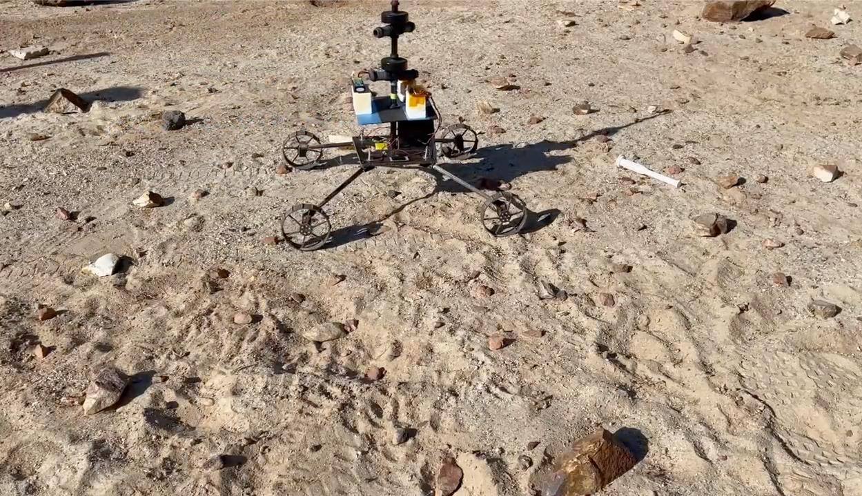
Section titled “Dedicated fetch rover (Sample Fetch Rover)”ESA and ASI funded the SFR, built by Airbus Defense and Space at Stevenage [9][10]. Its 2020 status was 150 to 180 kg and a 20 km traverse in 150 sols [10], and a 2018 to 2019 mission analysis planned up to 20 km one way from the lander to the depot, with 5 sols for deployment and checkout and 20 sols for sample transfer [23]. Launch was set for 2028 and arrival for mid 2030 [14]. A 2009 JPL trade study of sample handling for a notional return rover had proposed rock cores about 1 cm by 5 cm and at least 20 cores [4]. The vehicle was never built; the mission was canceled before its thermal testing [14]. Locomotion and vision reached bench and simulation stage, described below. The 2022 architecture replaced it with two helicopters, saving mass and cost [15]. The end-2023 campaign architecture is a snapshot taken before an independent review [7].
Rotorcraft with wheels and an arm (Sample Recovery Helicopter)
Section titled “Rotorcraft with wheels and an arm (Sample Recovery Helicopter)”The SRH is a proposal backed by ground-test rotors and a ground mobility model. It is two Ingenuity-derived coaxial helicopters, backups for Perseverance, deployed from the top of the lander [15]. Design details are in the sections below. Next-generation Mars rotorcraft concepts beyond it include a 17.7 kg hexacopter, for which thin ROAMX blades were analyzed for torsional stability and loads [28]. These are analysis only.
Learned tube detection and pose
Section titled “Learned tube detection and pose”Four published pipelines address finding the tube; none has run on Mars.
- A YOLOv3-tiny detector trained on photorealistic synthetic scenes with classical contour pose estimation was closed-loop tested on the ExoTeR rover on an indoor Mars testbed [3].
- A benchmark on 824 Mars Yard images compared a Line2D template matcher with Mask R-CNN [5].
- A YOLOv8 segmentation network with angle-guided perspective-n-point localizes the tube glove for the lander’s Sample Transfer Arm. Results are from synthetic renders, with flight processor runtime scaled from a desktop by clock ratio [11].
- Localizing a rover in aerial maps built from helicopter imagery was tested in the Mars Yard across feature detectors, viewing angles and times of day, as a way to use helicopter products for ground navigation [34].
Terrain-aware traverse planning
Section titled “Terrain-aware traverse planning”A proposed three-step method predicts slip and speed from HiRISE and thermal inertia data, plans a sol’s traverse over the resulting map, and deploys a shear vane if onboard slip monitoring is inconclusive. Trials are simulations over one annotated map area, and the speed distributions were assumed from a single published mean and maximum per category [6].
Rover and helicopter operations
Section titled “Rover and helicopter operations”Two analog campaigns tested how a helicopter changes operations. A five sol simulation at Rainbow Basin had the helicopter fly 1322 m and acquire about 16 Gbit against the rover’s 7 Gbit, but only 552 Mbit reached planners in time to affect decisions, because the platforms shared a downlink [26]. A July to August 2022 field campaign at the Holuhraun lava flow ran a 14 sol rover mission against a helicopter-only mission, with the rover’s planned 200 m traverse revised to 245 m [27].
Rotor and airfoil development for Mars
Section titled “Rotor and airfoil development for Mars”Airfoil tests in the Tohoku Mars Wind Tunnel at Re 20,000 and Mach 0.60 gave a maximum lift-to-drag ratio of 12.2 for the roamx-0201 cambered plate [29]. The Ingenuity clf5605 section measured a lift coefficient of 0.770 and a drag coefficient of 0.0985 at 6 degrees, and two models of the same nominal geometry differed in lift by 11 to 19 percent [29]. Full-scale hover tests of ROAMX rotors in a vacuum chamber reached a peak figure of merit of 0.574 against 0.445 for an Ingenuity replica at 0.015 kg/m3 [30]. These are ground tests at room temperature.
Mission profile and design details
Section titled “Mission profile and design details”| Parameter | Value | Source |
|---|---|---|
| SFR launch | 2028 on the Sample Retrieval Lander | [14] |
| SFR arrival | mid 2030 | [14] |
| SFR mass | 150 to 180 kg, maximum expected value | [10] |
| Orbiting sample capacity | up to 30 tubes in an 8 kg design | [10] |
| SFR surface duration | 150 sols | [10] |
| SFR traverse | 20 km in 150 sols | [10] |
| SRH deployment | from the top of the Sample Retrieval Lander | [15] |
| SRH role | backup to Perseverance for depot retrieval | [15] |
SFR locomotion
Section titled “SFR locomotion”The locomotion subsystem is a four-wheel-drive, four-wheel-steer deployable design with NASA superelastic spring tires, unusual among Mars rovers, which have all been six-wheeled [12]. Lander volume forced the tires down from 70 cm to 55 cm. The vehicle has a 130 by 97 cm footprint, 37.5 cm ground clearance, a 20 degree slope capability and a 29.5 cm single-sided obstacle climb on flat compact soil, with a nominal speed of 6.7 cm/s that averages 3.7 cm/s once navigation pauses are counted, more than 200 m per sol, and an energy cost of 3.1 kJ/m against 6.9 kJ/m for a six-wheeled alternative [12]. These are dynamic-simulation figures from before the vehicle-level test campaign. The tire design still needed another iteration after a life test failure. The related ExoMars locomotion model was a breadboard in an 11 m by 11 m indoor sandpit, at Earth gravity rather than Mars gravity [12][2].
Tube detection results
Section titled “Tube detection results”The YOLOv3-tiny pipeline takes 2808.62 ms per inference on an ARM Cortex-A72 and 33.46 ms with a Coral USB TPU, a factor of 84; pose estimation costs 14.12 ms on the ARM [3]. Closed-loop tests detected the tube out to 5 m, with a mean orientation error of 3.23 degrees from the close-range camera and 10.75 degrees from the navigation camera [3]. On the Mars Yard set, Mask R-CNN reached an average precision of 0.911 to 0.918 at an IoU of 0.5 against 0.255 for the Line2D matcher, which fails where shadows and bedrock edges mimic the tube’s parallel contours; recall for the better method stayed near 0.55 to 0.58 [5].
The Sample Transfer Arm is a 7-joint arm with a force-torque sensor, a placement budget of 9.35 mm lateral at the orbiting sample, a 350 N axial preload requirement and an insertion envelope of 15 N tip force [9].
SFR thermal design
Section titled “SFR thermal design”The rover carried no radioisotope heater units and relied on electrical heating against a -130 C night. The dominant leak is conduction and convection through the CO2 atmosphere, so a gas insulation design around the hot zones was required [14]. Viking used 10 to 20 cm of fibrous insulation, Pathfinder a 50 mm honeycomb filled with foam plus another 50 mm, Sojourner silica aerogel, and MER 25 mm carbon-opacified aerogel bricks. From MSL onward JPL used a 25 mm CO2 gas gap, with 50 mm proposed for the Sample Return Lander [14]. JPL found convection onset at about 76 mm, while the ExoMars campaign found none at 30 mm, weak convection at 60 mm and significant convection at 120 mm and above [14]. The proposed SFR test of five configurations was never run.
The orbiting sample container is a passive thermal system whose cruise predictions are -70 to +15 C, with a -20 C steady state requirement for up to ten years [8].
SRH vehicle
Section titled “SRH vehicle”The SRH keeps Ingenuity’s two counter-rotating coaxial rotors, solar panel, mast and carbon fiber legs. Two identical vehicles are carried because a failure anywhere in a coaxial rotor system grounds the aircraft [15]. Changes are a ground mobility system with tank-like steering and four lightweight wheels, a manipulation arm specified to grasp tubes of up to 150 g while massing under 100 g, higher-capacity batteries, a larger solar array, eight additional servos, an additional camera and in-flight absolute localization. Two Ingenuity parts, the radio and the 801 Snapdragon computer, were unavailable and are replaced by newer models [15]. The vehicle is about 2.5 kg against Ingenuity’s 1.8 kg [15].
| Parameter | Value | Source |
|---|---|---|
| Rotor radius | 0.6 to 0.7 m trade range; 0.7 m baseline from March 2023 | [15] |
| Rotor speed range in test | 2043 to 2500 RPM | [15] |
| Total mass | about 2.5 kg | [15] |
| Ground mobility | tank-like steering, four wheels | [15] |
| Arm target mass | under 100 g | [15] |
| Tube capacity | up to 150 g per tube | [15] |
| Servos added over Ingenuity | 8 | [15] |
| Vehicles | 2, identical | [15] |
| Optimized rotor peak figure of merit | 0.55 to 0.59 at blade loading 0.12 to 0.13 | [13] |
Rotor testing
Section titled “Rotor testing”CAMRAD II was used to optimize rotor size and planform, giving a larger radius, a similar chord and a twist close to Ingenuity’s [15]. Testing in the JPL 25 ft Space Simulator ran three campaigns: Ingenuity Engineering Design Model 1 with and without a cruciform box standing in for the lander takeoff platform, a transonic single-rotor rig, and an SRH dual rotor test [13]. The Ingenuity rotor peaks in figure of merit at blade loading 0.13, loses efficiency above tip Mach 0.75, and did not meet the SRH requirement [13]. The redesigned 0.706 m rotor rose from a figure of merit of 0.55 at 0.0120 kg/m3 to 0.59 at 0.0185 kg/m3 and met the requirement, so no further blade iterations were run [15][13]. Runs were limited to about 60 s by motor thermal limits. Two campaigns used a single force-torque sensor for the coaxial pair, so per-rotor forces were not resolved [15].
Takeoff from the lander
Section titled “Takeoff from the lander”Ingenuity took off from the ground after deployment from the underside of Perseverance [1]. The SRH lifts off from the top of the lander through a Lift-off Adapter and Inverted Retention box, with no flight precedent. Mid-fidelity RotCFD runs show 15 m/s outwash developing over 8 to 20 s of a rapid collective ramp, and blade clearance from the lander must be shown for the whole sequence [15].
What is not established
Section titled “What is not established”Nothing in the SFR or SRH architectures has flown or been qualified. The SFR was canceled before its gas-insulation test, so none of the five proposed configurations has data [14]. Its locomotion figures are simulation [12]. Tube detection results come from indoor testbeds, the Mars Yard and synthetic renders, with no Martian imagery tested [3][5][11], and recall near 0.55 has not been translated into a fetch success rate [5]. The accelerator power savings that motivated the hardware choice were not measured [3].
For the SRH, rotor results are hover only at room temperature, with per-rotor forces unresolved in the single-sensor campaigns [13]. Figure of merit in the preliminary study came from estimated motor efficiency rather than measured shaft power, and the ground mobility system and arm had not been demonstrated [15]. Airfoil data at the relevant Reynolds number disagree between nominally identical models [29]. Takeoff from the lander box, outwash and blade clearance remain analysis [15]. The helicopter-augmented operations results are from analog simulations with shared downlink [26][27]. Every campaign-level mass, date and orbit is a snapshot of a plan under review [7][10].
References
- Balaram, J., Aung, M. and Golombek, M. P. (2021). The Ingenuity Helicopter on the Perseverance Rover
. Space Science Reviews. Source
BibTeX
@article{balaram2021ingenuity, title = {The Ingenuity Helicopter on the Perseverance Rover}, author = {Balaram, J. and Aung, MiMi and Golombek, Matthew P.}, journal = {Space Science Reviews}, volume = {217}, year = {2021}, doi = {10.1007/s11214-021-00815-w} } - Ball, A. J., Blancquaert, T., Bayle, O., Lorenzoni, L. V. and Haldemann, A. F. C. (2022). The ExoMars Schiaparelli Entry, Descent and Landing Demonstrator Module (EDM) System Design
. Space Science Reviews. Source
BibTeX
@article{ball2022exomars, title = {The ExoMars Schiaparelli Entry, Descent and Landing Demonstrator Module (EDM) System Design}, author = {Ball, Andrew J. and Blancquaert, Thierry and Bayle, Olivier and Lorenzoni, Leila V. and Haldemann, Albert F. C.}, journal = {Space Science Reviews}, volume = {218}, year = {2022}, doi = {10.1007/s11214-022-00898-z}, abstract = {Abstract The Entry, Descent and Landing Demonstrator Module (EDM) named Schiaparelli, was the ESA-led Mars lander element of the ESA-Roscosmos ExoMars 2016 mission. Following launch on 14 March 2016 with the ExoMars Trace Gas Orbiter (TGO) and cruise to Mars, Schiaparelli separated for encounter with Mars to demonstrate entry, descent and landing technologies. Although on 19 October 2016 the final touchdown and surface operation were not achieved, other aspects were demonstrated and reported via real-time telemetry transmitted at 8 kbps in UHF during entry and descent. This paper presents a technical description of the elements of the Schiaparelli EDM system and its operation, plus reference to published post-flight analyses of the data obtained.} } - Castilla-Arquillo, R., Perez-del-Pulgar, C. J., Paz-Delgado, G. J. and Gerdes, L. (2022). Hardware-accelerated Mars Sample Localization via deep transfer learning from photorealistic simulations
. IEEE Robotics and Automation Letters, 4. Source
BibTeX
@article{castillaarquillo2022hardware, title = {Hardware-accelerated Mars Sample Localization via deep transfer learning from photorealistic simulations}, author = {Castilla-Arquillo, Raul and Perez-del-Pulgar, Carlos J. and Paz-Delgado, Gonzalo J. and Gerdes, Levin}, journal = {IEEE Robotics and Automation Letters}, volume = {7}, number = {4}, pages = {12160--12167}, year = {2022}, doi = {10.1109/lra.2022.3219306}, abstract = {The goal of the Mars Sample Return campaign is to collect soil samples from the surface of Mars and return them to Earth for further study. The samples will be acquired and stored in metal tubes by the Perseverance rover and deposited on the Martian surface. As part of this campaign, it is expected that the Sample Fetch Rover will be in charge of localizing and gathering up to 35 sample tubes over 150 Martian sols. Autonomous capabilities are critical for the success of the overall campaign and for the Sample Fetch Rover in particular. This work proposes a novel system architecture for the autonomous detection and pose estimation of the sample tubes. For the detection stage, a Deep Neural Network and transfer learning from a synthetic dataset are proposed. The dataset is created from photorealistic 3D simulations of Martian scenarios. Additionally, the sample tubes poses are estimated using Computer Vision techniques such as contour detection and line fitting on the detected area. Finally, laboratory tests of the Sample Localization procedure are performed using the ExoMars Testing Rover on a Mars-like testbed. These tests validate the proposed approach in different hardware architectures, providing promising results related to the sample detection and pose estimation.} } - Collins, C., Younse, P. and Backes, P. (2009). Planetary sample caching system design options
. AIAA SPACE Conference. Source
BibTeX
@inproceedings{collins2009planetary, title = {Planetary sample caching system design options}, author = {Collins, Curtis and Younse, Paulo and Backes, Paul}, booktitle = {AIAA SPACE Conference}, publisher = {American Institute of Aeronautics and Astronautics}, year = {2009}, doi = {10.2514/6.2009-6506}, abstract = {Potential Mars Sample Return missions would aspire to collect small core and regolith samples using a rover with a sample acquisition tool and sample caching system. Samples would need to be stored in individual sealed tubes in a canister that could be transfered to a Mars ascent vehicle and returned to Earth. A sample handling, encapsulation and containerization system (SHEC) has been developed as part of an integrated system for acquiring and storing core samples for application to future potential MSR and other potential sample return missions. Requirements and design options for the SHEC system were studied and a recommended design concept developed. Two families of solutions were explored: 1)transfer of a raw sample from the tool to the SHEC subsystem and 2)transfer of a tube containing the sample to the SHEC subsystem. The recommended design utilizes sample tool bit change out as the mechanism for transferring tubes to and samples in tubes from the tool. The SHEC subsystem design, called the Bit Changeout Caching(BiCC) design, is intended for operations on a MER class rover.} } - Daftry, S., Ridge, B., Seto, W., Pham, T., Illhardt, P., Maggiolino, G., Van der Merwe, M., Brinkman, A., Mayo, J., Kulczyski, E. and Detry, R. (2021). Machine Vision based Sample-Tube Localization for Mars Sample Return
. IEEE Aerospace Conference. Source
BibTeX
@inproceedings{daftry2021machine, title = {Machine Vision based Sample-Tube Localization for Mars Sample Return}, author = {Daftry, Shreyansh and Ridge, Barry and Seto, William and Pham, T. and Illhardt, P. and Maggiolino, Gerard and Van der Merwe, Mark and Brinkman, A. and Mayo, John and Kulczyski, E. and Detry, Renaud}, booktitle = {IEEE Aerospace Conference}, pages = {1-12}, publisher = {IEEE}, year = {2021}, doi = {10.1109/aero50100.2021.9438364}, abstract = {A potential Mars Sample Return (MSR) architecture is being jointly studied by NASA and ESA. As currently envisioned, the MSR campaign consists of a series of 3 missions: sample cache, fetch and return to Earth. In this paper, we focus on the fetch part of the MSR, and more specifically the problem of autonomously detecting and localizing sample tubes deposited on the Martian surface. Towards this end, we study two machine-vision based approaches: First, a geometry-driven approach based on template matching that uses hard-coded filters and a 3D shape model of the tube; and second, a data-driven approach based on convolutional neural networks (CNNs) and learned features. Furthermore, we present a large benchmark dataset of sample-tube images, collected in representative outdoor environments and annotated with ground truth segmentation masks and locations. The dataset was acquired systematically across different terrain, illumination conditions and dust-coverage; and benchmarking was performed to study the feasibility of each approach, their relative strengths and weaknesses, and robustness in the presence of adverse environmental conditions.} } - Hedrick, G. and Gu, Y. (2021). Terrain-aware traverse planning for a Mars sample return rover
. Advanced Robotics, 21-22. Source
BibTeX
@article{hedrick2021terrain, title = {Terrain-aware traverse planning for a Mars sample return rover}, author = {Hedrick, G. and Gu, Y.}, journal = {Advanced Robotics}, volume = {35}, number = {21-22}, pages = {1286-1301}, publisher = {Informa UK Limited}, year = {2021}, doi = {10.1080/01691864.2021.1955000} } - Martin-Mur, T., Sánchez Pérez, J. M., Wilson, R., Olikara, Z., Jesick, M., Patel, R. and Spencer, D. (2024). The NASA/ESA Mars Sample Return Campaign
. Root. Source
BibTeX
@inproceedings{martinmur2024nasa, title = {The NASA/ESA Mars Sample Return Campaign}, author = {Martin-Mur, Tomas and Sánchez Pérez, José Manuel and Wilson, Roby and Olikara, Zubin and Jesick, Mark and Patel, Rohan and Spencer, David}, journal = {Root}, publisher = {JPL Open Repository}, year = {2024}, doi = {10.48577/jpl.lysmhs}, abstract = {This paper outlines the proposed architecture of the Mars Sample Return (MSR) campaign planned in collaboration by the National Aeronautics and Space Administration (NASA) and the European Space Agency (ESA). The goal of the campaign is to bring to Earth a scientifically selected, diverse set of Mars samples being currently collected by the NASA Perseverance rover. The planned campaign involves an Earth Return Orbiter (ERO) built and operated by ESA and a Sample Retrieval Lander (SRL) built and operated by NASA. The paper describes the high-level mission design and timeline of the campaign and outlines its constituent components.} } - Miller, J. (2025). Interface and Thermal Design Overview of the Sample Retrieval Lander (SRL) Orbiting Sample (OS)
. Annual AAS Guidance and Control Conference. Source
BibTeX
@inproceedings{miller2025interface, title = {Interface and Thermal Design Overview of the Sample Retrieval Lander (SRL) Orbiting Sample (OS)}, author = {Miller, Jennifer}, booktitle = {Annual AAS Guidance and Control Conference}, publisher = {JPL Open Repository}, year = {2025}, doi = {10.48577/jpl.fhdkrw} } - Muirhead, B. K., Nicholas, A. K., Umland, J., Sutherland, O. and Vijendran, S. (2019). Mars Sample Return mission concept status
. International Astronautical Congress, IAC-19-A3.3A. Source
BibTeX
@inproceedings{muirhead2019bmars, title = {Mars Sample Return mission concept status}, author = {Muirhead, Brian K. and Nicholas, Austin K. and Umland, Jeffrey and Sutherland, Orson and Vijendran, Sanjay}, booktitle = {International Astronautical Congress}, number = {IAC-19-A3.3A}, pages = {1-8}, year = {2019}, doi = {10.1109/aero47225.2020.9172609}, abstract = {This paper will provide an overview of current concepts and options for the architecture and design of a Mars Sample Return Mission, including the Sample Retrieval Lander (SRL) (developed by NASA) and the Earth Return Orbiter (ERO) (developed by ESA). Key mission objectives and the overall campaign will be described, including the mission's concept of operations and a notional timeline from launch to entry, through surface operations, to delivery of the samples to Mars orbit and return to Earth. The overall SRL lander vehicle concept will be described, including current options being evaluated. Key lander element options that have been studied will be discussed, including the Mars Ascent Vehicle (MAV), Sample Fetch Rover (provided by ESA), Orbiting Sample container (OS), and sample tube transfer robotics systems. For the ERO the vehicle concept will be described including key interfaces with the Capture/Containment and Return System (CCRS). Specific challenges and approaches for addressing those challenges will be discussed, including key technical margins and backward planetary protection. The information provided about possible Mars sample return architectures is for planning and discussion purposes only. NASA has made no official decision to implement Mars sample return.} } - Muirhead, B. K., Nicholas, A. K., Umland, J., Sutherland, O. and Vijendran, S. (2020). Mars Sample Return Campaign Concept Status
. Acta Astronautica. Source
BibTeX
@article{muirhead2020mars, title = {Mars Sample Return Campaign Concept Status}, author = {Muirhead, Brian K. and Nicholas, Austin K. and Umland, Jeffrey and Sutherland, Orson and Vijendran, Sanjay}, journal = {Acta Astronautica}, publisher = {JPL Open Repository}, year = {2020}, doi = {10.48577/jpl.k22uns} } - Posada, D., Pham, T.-H., Mavrakis, N. and Bailey, P. (2024). Robust Tube Localization for Mars Sample Return: Lightweight YOLO-Segmentation with Angle-Guided PnP
. Pattern Recognition. Source
BibTeX
@unpublished{posada2024robust, title = {Robust Tube Localization for {Mars Sample Return}: Lightweight {YOLO}-Segmentation with Angle-Guided {PnP}}, author = {Posada, Daniel and Pham, Tu-Hoa and Mavrakis, Nikos and Bailey, Philip}, journal = {Pattern Recognition}, volume = {171}, pages = {112190}, publisher = {Elsevier BV}, year = {2024}, doi = {10.1016/j.patcog.2025.112190} } - Ridolfi, P., Pecover, D., Pulker, S., Wayman, A., Zekri, E., Zwick, M., Do, S., Eremenko, A., Heverly, M., Moreland, S., Nicholas, A., Asnani, V., Ghotbi, B., Jessen, S. and Rehmatullah, F. (2021). Development of the Sample Fetch Rover Locomotion Subsystem
. International Astronautical Congress. Source
BibTeX
@inproceedings{ridolfi2021development, title = {Development of the Sample Fetch Rover Locomotion Subsystem}, author = {Ridolfi, Paolo and Pecover, David and Pulker, Stephen and Wayman, Alastair and Zekri, Eric and Zwick, Martin and Do, Sydney and Eremenko, Alexander and Heverly, Matthew and Moreland, Scott and Nicholas, Austin and Asnani, Vivake and Ghotbi, Bahareh and Jessen, Sean and Rehmatullah, Faizan}, booktitle = {International Astronautical Congress}, publisher = {JPL Open Repository}, year = {2021}, url = {https://dataverse.jpl.nasa.gov/dataset.xhtml?persistentId=hdl:2014/55056} } - Schatzman, N. L., Koning, W. J. F., Russell, C. and Withrow-Maser, S. (2024). Performance Analysis and Data Processing for the Mars Sample Recovery Helicopter in the Jet Propulsion Laboratory 25-ft Space Simulator
. Vertical Flight Society Annual Forum and Technology Display. Source
BibTeX
@inproceedings{schatzman2024performance, title = {Performance Analysis and Data Processing for the Mars Sample Recovery Helicopter in the Jet Propulsion Laboratory 25-ft Space Simulator}, author = {Schatzman, Natasha L. and Koning, Witold J. F. and Russell, Carl and Withrow-Maser, Shannah}, booktitle = {Vertical Flight Society Annual Forum and Technology Display}, pages = {1-11}, institution = {NASA Ames Research Center}, year = {2024}, doi = {10.4050/f-0080-2024-1357}, abstract = {On April 19, 2021, Ingenuity became the first helicopter to fly on Mars at Jezero Crater, completing a total of 72 flights by the end of its mission. The success of Ingenuity resulted in various research efforts to further exploreMars via vertical flight, including two optimized Ingenuity-sized helicopters proposed to retrieve samples for the 2028 Mars Sample Return mission. To aid in the design process for the two proposed Sample Retrieval Helicopters, both heritage and optimized, increased diameter rotors were tested at the NASA Jet Propulsion Laboratory in the 25-ft Space Simulator. Three test campaigns were performed using the Ingenuity rotors and optimized Sample Retrieval Helicopter (SRH) rotors for several rotor speeds, densities, configurations, and collectives to identify performance limitations. These three test campaigns included the Ingenuity Engineering Design Model 1 (EDM-1) with and without a cruciform box, Transonic Rotor Test (TRT) rig, and SRH Dual Rotor Test (DRT). Experimental setup, test matrix, data processing, data quality, and performance results for EDM-1, TRT, and DRT campaigns are presented and discussed. Experimental results from the test campaigns will aid in future experimental methods and validation efforts for planetary rotorcraft exploration.} } - Tamkin, L. and Dunlop, A. (2024). Mars Sample Return, Sample Fetch Rover, Gas Insulation Design and Test Definition
. International Conference on Environmental Systems. Source
BibTeX
@inproceedings{tamkin2024mars, title = {Mars Sample Return, Sample Fetch Rover, Gas Insulation Design and Test Definition}, author = {Tamkin, Luke and Dunlop, Arthur}, booktitle = {International Conference on Environmental Systems}, organization = {Airbus Defence and Space, Stevenage}, year = {2024}, doi = {10.32865/2346/98972}, abstract = {The Sample Fetch Rover (SFR) was a key element of the Mars Sample Return program, having the objective to locate, retrieve and return samples cached by the Mars 2020 (Perseverance) rover. Designed for autonomous operations and fast mobility on Mars terrains, the Sample Fetch Rover mission profile included traverse to the "depot" where Perseverance will have left the tubes containing soil and rock samples; collection and on-board storage of the tubes, and their transport back to the Mars Ascent Vehicle. A key design driver for SFR, as with any Martian mission, is keeping equipment warm during the cold Martian night, with environmental temperatures dropping to -130°C. SFR does not have any form of radioactive heating and relies entirely on electrical heating to sustain internal temperatures. As such, heat leaks to the cold environment must be minimised, with the main heat leak being via the CO2 atmosphere. This imposed a need for an efficient gas insulation design around hot zones within SFR. To achieve this a literature review of previous Martian gas testing was conducted, identifying key parameters for a gas insulation design such as maximum gap size which suppresses convection. From this, multiple designs for novel gas insulation solutions for SFR were created and a test was defined to determine empirically which design provides the highest level of insulation. This paper details the literature review, the various novel gas insulation designs and the proposed testing for design selection.} } - Withrow-Maser, S., Johnson, W., Tzanetos, T., Grip, H., Koning, W., Schatzman, N., Young, L., Chan, A., Ruan, A., Cummings, H., Allan, B., Malpica, C., Meyn, L., Pipenberg, B. and Keennon, M. (2023). Mars Sample Recovery Helicopter: Rotorcraft to Retrieve the First Samples from the Martian Surface
. Vertical Flight Society Annual Forum and Technology Display, 20230005247. Source
BibTeX
@inproceedings{withrowmaser2023mars, title = {Mars Sample Recovery Helicopter: Rotorcraft to Retrieve the First Samples from the Martian Surface}, author = {Withrow-Maser, Shannah and Johnson, Wayne and Tzanetos, Theodore and Grip, Havard and Koning, Witold and Schatzman, Natasha and Young, Larry and Chan, Athena and Ruan, Allen and Cummings, Haley and Allan, Brian and Malpica, Carlos and Meyn, Larry and Pipenberg, Benjamin and Keennon, Matthew}, booktitle = {Vertical Flight Society Annual Forum and Technology Display}, number = {20230005247}, pages = {1-8}, institution = {NASA Ames Research Center and Jet Propulsion Laboratory}, year = {2023}, doi = {10.4050/f-0079-2023-17969}, abstract = {The Mars Sample Return Mission (MSR) will carry the next set of Mars helicopters, Sample Recovery Helicopters (SRHs), to the Martian surface. After successfully demonstrating extraterrestrial flight in 2021, Ingenuity has acted as a} } - (2017). NASA: Mars Sample Return. science.nasa.gov/mission/mars-sample-return
BibTeX
@misc{nasamars2, title = {NASA: Mars Sample Return}, organization = {science.nasa.gov}, year = {2017}, url = {https://science.nasa.gov/mission/mars-sample-return/} } - (2026). ESA: Mars Sample Return. esa.int/Science_Exploration/Human_and_Robotic_Exploration/Exploration...
BibTeX
@misc{esamars,
  title = {ESA: Mars Sample Return},
  organization = {esa.int},
  year = {2026},
  url = {https://www.esa.int/Science_Exploration/Human_and_Robotic_Exploration/Exploration/Mars_sample_return}
}