NASA JPL Space Simulators
NASA/JPL-Caltech. Public domain (NASA / US government work).
The problem
Section titled “The problem”A robotic arm, rover or rotorcraft bound for Mars or deep space must survive combined vacuum, solar heating and cold that no single Earth environment produces on its own, and the qualification article is usually the vehicle that flies. NASA JPL’s environmental test organization answers with two thermal vacuum chambers built decades apart. The 25-Foot Space Simulator in Building 150 is a 1961 chamber with off-axis xenon solar simulation, built to reproduce cruise heating and deep-space cold on a whole spacecraft [1][5]. The 10-Foot Vertical Space Simulator has a hydraulic-lift floor so that a tightly packed configuration of rocks, tools and an arm stays reachable at Mars pressure and temperature, and it has no solar simulation [2]. Both hold Mars conditions on flight hardware that cannot drive; driving is done outdoors at the MarsYard, which holds neither pressure nor temperature [37]. The 25-Foot chamber is NASA-owned and available to other government agencies and to private industry [1][2].
The two designs split because accurate solar heating and full mechanical access are hard to build into one machine. The solar simulator was the harder problem from the start: the operator’s 1966 account of the first two years of use, testing Ranger, Mariner and Surveyor hardware, spends most of its length on the light source, and names it the largest source of trouble, above outgassed cable insulation contaminating test items and a stopped mechanical pump that let diffusion pumps backstream oil onto a spacecraft and arc its electronics [5]. A 1964 to 1965 spectral characterization of the beam from 133 mercury-xenon arc lamps found it two to three times too strong in some visible bands and only a third of solar intensity in others, although the integrated near-infrared matched the solar spectrum to within half a percent [6]. An absorptance computed against the real solar spectrum is therefore wrong for a coating whose absorption concentrates in the mismatched bands, so thermal balance plans are built around the beam JPL has. The optical chain (xenon lamps, integrating lens unit, large parabolic collimating mirror) also constrains upkeep: the mirror was pulled, stripped, re-plated and re-aluminized inside the chamber in 1994, using the chamber as the coating vessel [7].
What has flown
Section titled “What has flown”Ranger, Mariner and Surveyor, 1963 to 1964. The 25-Foot chamber’s first two years ran a standard progression from solar panel to temperature control model to proof test model to flight spacecraft [5]. They produced the contamination and backstreaming incidents above and a beam map of 184 W/ft2 nominal with a 6 percent spread over the central 4 ft. The real Sun’s angular divergence of plus or minus 0.267 degrees against a measured simulator divergence of plus or minus 5.3 degrees forced test engineers to redesign sun shades and shadowing hardware [5].
Mars Exploration Rover, November 2002 to April 2003. Both flight spacecraft went through cruise thermal-vacuum testing in the 25-Foot chamber, suspended on steel cables inside the aeroshell, under the xenon solar simulator on the cruise array and quartz lamp arrays on off-sun surfaces, across eleven thermal cases per spacecraft including an entry-descent-landing case with the Heat Rejection System off [9]. Each rover then went to the 10-Foot chamber for an 8 torr nitrogen surface thermal test with no solar simulation, standing up and deploying through hot and cold diurnal cycles. Margins held in every case; the tightest was a 3.8 C battery cell-to-cell gradient against a 5 C requirement [9]. The one new technique was a controlled re-pressurization of the 25-Foot chamber from 1e-1 Torr to 8 Torr in six minutes to simulate telecom operation during descent, never attempted there before [8].
Phoenix, 2008. The arm flew without a chamber test of the combination that later failed it [4]. Insolation on ice-bearing regolith in the aluminum scoop warmed the sample enough that it adhered to the scoop wall and would not fall through the TEGA inlet on the first two attempts; a third sample obtained by scraping, with less ice, did not congeal and was delivered [4]. The University of Arizona Payload Interoperability Testbed reproduced the delivery geometry closely enough that overlaid Robotic Arm Camera images from Mars and from the testbed were used to correct scoop positioning, but not the thermal combination.
Mars Science Laboratory, 2009 and 2011. The January 2009 launch [18] and cruise solar thermal vacuum test in Building 150 was prepared with rehearsed failures, called Gremlin Sessions, injected over the comm net to both shifts. A loss-of-building-power scenario exposed a faulty transfer switch and mis-assigned UPS circuits before flight hardware entered the chamber, and several rehearsed failures recurred during the 5.5 day test: a magnitude 5.0 earthquake during final pumpdown, loss of commanding, solar simulator lamp coolant leaks and a flight computer reset [18]. In 2011 the 900 kg Curiosity rover ran 16 days in simulated cruise under vacuum and in simulated Mars surface conditions under 8 torr nitrogen at mission-extreme hot and cold boundaries [3]. All thermal hardware performed nominally and the Rover Heat Rejection System performed better than predicted; the data correlated the thermal models that predicted Gale Crater performance across the 669 sol surface mission [3].
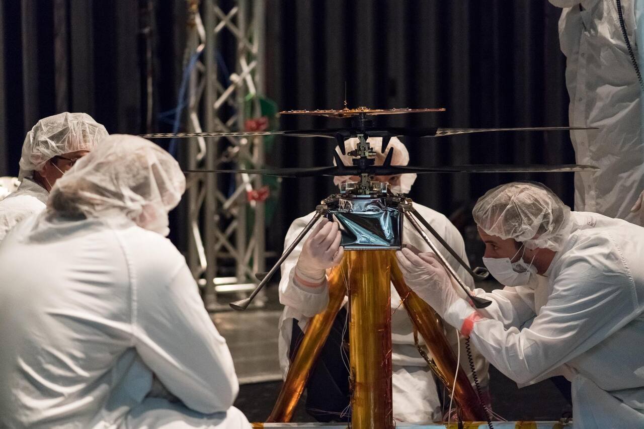
Mars Helicopter, 2018 and after. The Ingenuity flight model went through a 40 C bakeout, steady state thermal balance in vacuum and at Mars pressure with gaseous-nitrogen backfill, a -90 C cold cycle, and cold functional testing at -50 C shroud including blade spin-ups at 50 and 1800 rpm [11]. Gas conduction across internal gaps, not radiation, was the largest driver of survival energy at Mars pressure; the fix was geometric, enlarging the fuselage by 25 mm in one direction and 15 mm in another, plus a low emissivity inner blanket. The tested article carried ground support cabling that added 50 to 60 percent more heat loss than flight, so the survival energy budget closes only in the correlated model [11].
Mars 2020, 2016 to 2021. A 2016 instrument test in the 25-Foot chamber landed midway through a control-system replacement, so staff ran pump-down, cooldown and CO2 backfill by hand against an 81-step procedure with analog gauges in every cabinet and field operators on noise-canceling radios, completing 38 runs; redundant Hand/Off/Auto switches are now standard on refurbished chamber control systems [10]. The May 2019 system thermal vacuum test ran six days (cut short by an anomaly) on a surrogate chassis and a qualification MMRTG in place of the unavailable flight rover. It validated cruise thermal design and heat rejection system leak tightness, found reversed thermostat wiring on one instrument and reversed catalyst-bed PRT wiring on landing engines 3 through 8, and showed that a build-to-print rebuild of an MSL-heritage design still shifted zone temperature ranges by 2 to 13 C [14]. The 10-Foot chamber then hosted a two year sampling and caching qualification series at about 7 torr and -70 C, nominally -65 C cold with stress cases to -115 C, on a floor of geoanalogue rocks including deliberately chosen challenge rocks [2]. Six qualification coring bits took 66 cores, one abrading bit made 34 patches, one regolith bit collected regolith twice and 17 seals were activated; flight software itself, not a test build, ran in the test environment [2].
What is being tried now
Section titled “What is being tried now”Every approach below has been exercised on the ground; none is a flight demonstration of a chamber technique.
Closing the combined-environment gap by splitting cases. The Mars Helicopter reference states that even JPL’s largest chamber cannot combine Mars air density, Mars-relevant temperature and true 1/3 g, so free-flight tests ran at Mars density and ambient temperature with a gravity offload rig, and thermal qualification ran density and temperature cases separately from the flight dynamics cases [12]. Test status: ground-tested and flown as qualification practice [11][12].
Rehearsed failure and manual fallback. Gremlin Sessions in the 2009 MSL test [18] and the 2016 hand-operated campaign [10] treat the facility and its crew as part of the system under test. Status: ground practice, with the transferable result being the switch standard in [10].
Photogrammetry under solar and cryo-vacuum load. In September 2008 a remotely actuated camera on a mobility cart measured thermo-elastic deformation of a 5 m deployable reflector to 0.025 mm RMS over the aperture across a 36-hour solar cycle test, which the program credited with raising the reflector’s deformation analysis from TRL 3 to TRL 6 [13]. Status: ground-tested on one article; ice forming on targets during cold soak was the one failure mode [13].
Simulation-first arm and drill validation. Target rocks are scanned into a point cloud and loaded into the Rover Sequencing and Visualization Program Hyperdrive simulator, and arm and drilling operations are validated in simulation before execution in the chamber [2]. Because the limited chamber space kept flight-like cameras from the rover’s true positions, the 3D environment model came from a fixed CAD model of the chamber plus rocks on keyed baseplates [2]. Status: ground-tested over the 2019 to 2021 campaign.
A ladder of cheaper venues beneath the chamber. The Mars 2020 testbed team ranks venues on hardware, avionics and flight software, and environmental fidelity: the Hexapod tilts a fixed chassis without rover kinematics, Scarecrow matches rover weight but not flight hardware, and the Vehicle System Testbed twin, OPTIMISM, covers system-level verification, dry runs, operations training and anomaly debug [20]. JPL’s Guidance and Control Spacecraft Autonomy Testbed combines a Simulink and F’ software testbed with hardware-in-the-loop platforms in the Robodome [35]. Mobility is established outside the chambers: the MER variable terrain tilt platform, a 16 foot square table run over 200 trials, gave slip that rose nonlinearly above about 10 degrees and reached 91 percent driving directly up a 20 degree slope on sand, and drives at Meridiani planned against those curves landed within 10 percent of the destination [21]. The outdoor MarsYard III covers 66 m by 36 m with 7 variable angle and cohesion slopes [37], and the Planetary Robotics Laboratory offers about 139 m2 of floor plus two indoor sand pits [22]. NASA’s consolidated best practices for planetary rover and tire mobility testing cover drawbar pull, slope and obstacle tests and list the absence of standard south pole simulants among open gaps [34]. Status: all in routine ground use.
Chamber repurposing. In twelve months the 10-Foot chamber was converted to an ion engine test chamber for the Prometheus/JIMO program, with six nude cryopumps rated 57,000 L/s of nitrogen each, a graphite liner and water-cooled shroud circuits, and was later converted back [19]. Arcing at a 10 kV feedthrough, floor shroud leaks and window coating were logged, and more than 20 shroud leaks were attributed to chlorine in supplemental city water attacking welds in shrouds that had run 40 years [19]. No achieved vacuum performance is reported.
Chambers and rigs at other centers. ESA’s Large Space Simulator at ESTEC is 15 m high by 10 m wide, about 2,300 m3, with a horizontal auxiliary chamber for the solar collimation optics [25]; its published envelope is a typical 5e-6 mbar (3e-7 mbar best), shrouds below 100 K in liquid nitrogen mode at 170 kW capacity or 150 to 350 K in gaseous mode, and a 6 m beam adjustable from 70 to 2600 W/m2 at plus or minus 4 percent [31]. It sits in a 6000 m2 cleanroom complex with Phenix and VTC 1.5 thermal vacuum chambers, shakers and an acoustic facility [32]. The ESTEC Mars Yard is an 8 by 8 m indoor bed of sand, gravel and rocks for locomotion, navigation and arm placement [26]. NASA Glenn built the Glenn Extreme Environment Rig, a 3 ft by 4 ft chamber of over 28 cubic feet intended for roughly 500 C and 100 bar with nine gas streams, because existing Venus chambers held about 1 cubic foot and reproduced only CO2 and N2; the paper predates commissioning [27], and a later briefing reports over 90 days of cumulative operation at Venus conditions without test data [28]. Glenn’s Planetary Exploration facilities add soil tanks, a single-wheel dynamometer, an excavation lab and the VOiD thermal-vacuum dust chamber [33]. The Lunar Dust Adhesion Bell Jar stirs simulant during pumpdown, bakes at 200 C at 1e-6 torr, thermal cycles to about -150 C and plasma-treats the surface, with no demonstration that the result resembles lunar regolith [29]. For entry heating, the Ames Thermophysics Facilities Branch operates arc jets, a ballistic range and an electric arc shock tube [30], with arc jet power of 10 to 60 MW and surface pressure of 0.01 to 75 kPa [36]. NASA’s Johnson Space Center Chambers A and B, built for Apollo and Gemini on a comparable scale, serve crewed rather than robotic programs [15]. JPL’s 1990s telerobotics and rover overviews describe tools these chambers later qualified [17]. A survey of flown and proposed lunar and Mars rovers compiles the shared temperature, vacuum and regolith envelope independently of any facility [16]. Radiation qualification is separate: two Cobalt-60 irradiators span 0.001 to 1 and 0.1 to 500 rad(Si)/s [23], and the Guidance and Control Section describes in-house testbeds as a capability overview [24].
The numbers
Section titled “The numbers”| Parameter | Value |
|---|---|
| Operator | NASA JPL environmental test organization [1] |
| Location | Pasadena, California, United States |
| Commissioned | 25-Foot Space Simulator, 1961; 10-Foot chamber date not published [1] |
| Type | Thermal vacuum chambers, one with off-axis solar simulation [1][2] |
| Simulant or terrain | No simulant bed. Geoanalogue rocks on keyed baseplates [2] |
| Instrumentation | 600 thermocouple channels and 40 RTD channels to the article [1] |
| Ground truth | Kendall cavity radiometer on the solar beam; six ion gauges [1] |
| Fidelity limits | Chamber conditions are hard to vary between tests and are held fixed [2] |
| Access | Available to other government agencies and to private industry [1] |
| Cited by | Curiosity [3], Phoenix arm [4] |
25-Foot Space Simulator [1]
Section titled “25-Foot Space Simulator [1]”| Parameter | Value |
|---|---|
| Working volume | 6.1 m diameter x 7.6 m high with the solar simulator; about 21.3 m high without |
| Test article limits | Wall hard points rated 10,000 lb each; door 4.6 x 7.6 m |
| Vacuum | 5 x 10^-5 torr in about 3 hours, into the 1 x 10^-6 torr range on cryopumps |
| Temperature | -185 C on liquid nitrogen; -125 to +100 C on gaseous nitrogen |
| Illumination | 2.0 to 11.0 solar constants, beam 8.5 to 18.5 ft, 37 xenon arc lamps |
| Gravity offload | None. Articles are hard mounted or suspended at 1 g |
| Instrumentation | 600 thermocouple, 40 RTD and 60 heater control channels to the article |
The chamber is 25.9 m high and 8.2 m in diameter [1]. Access is at ground level through a 4.6 by 7.6 m door, and articles enter on a monorail crane [1]. Support is either hard mounting to stanchions through the floor shroud onto an isolated seismic mass, or suspension from wall hard points [1]. An earlier facility description gives a 7.6 m diameter by 25.7 m tall chamber and a 5.8 m collimated beam to 2.3 solar constants at plus or minus 4 percent uniformity [8]. Pumping runs in four stages, with cryopumps and turbopumps taking it into the 1 x 10^-6 torr range [1]; a 2016 account gives 1e-6 Torr in about 90 minutes [10], consistent with pumpdown depending on loading and outgassing. A 2008 test reached about 1e-7 torr after facility preparation [13]. Mars surface conditions are a gas fill: about 8 torr of nitrogen for the MSL rover test [3], and 8 to 10 torr with shrouds between 20 C and -130 C for the MER surface test run in the 10-Foot chamber [8][9].
Thirty-seven xenon arc lamps feed an integrating lens unit, through a fused quartz window and off a 23 ft collimating mirror [1]. Two lens units and two mirrors give four beam combinations spanning 8.5 to 18.5 ft and 2.0 to 11.0 solar constants. The 18.5 ft beam at 2.0 solar constants has a 1.1 degree collimation half angle with 96.2 percent of energy inside 1 degree and uniformity of +0.6 to -1.4 percent; the 8.5 ft beam at 11.0 solar constants has a 2 degree half angle and plus or minus 5 percent [1]. The mirror was re-plated to 381 micrometers of electroless nickel, polished to 64 percent reflectivity and re-aluminized to about 89 percent after conditioning [7]. Facility instrumentation adds 140 thermocouple channels on shrouds, mirror and structure and three temperature-controlled quartz crystal microbalances [1].
10-Foot Vertical Space Simulator [2]
Section titled “10-Foot Vertical Space Simulator [2]”| Parameter | Value |
|---|---|
| Vacuum | About 7 torr for Mars surface work; base pressure not published |
| Temperature | Nominal cold testing at -65 C, stress cases to -115 C |
| Illumination | No solar simulator |
| Dimensions | 3.0 m by 13.7 m per the earlier description [8] |
| Layout | End bell on a hydraulic lift: first-floor level for access, second-floor level when sealed |
Comparison with other chambers
Section titled “Comparison with other chambers”| Facility | Figure | Marker |
|---|---|---|
| JPL 25-Foot, solar beam | 2.0 to 11.0 solar constants | [1] |
| ESTEC Large Space Simulator, solar beam | 70 to 2600 W/m2, 6 m | [31] |
| ESTEC Large Space Simulator, shroud | below 100 K, 170 kW (LN2) | [31] |
| Ames arc jet complex, power | 10 to 60 MW | [36] |
| MarsYard III, area | 66 m by 36 m, 7 slopes | [37] |
| JPL Radiation Effects Group, Co-60 | 0.001 to 1 and 0.1 to 500 rad(Si)/s | [23] |
What is not established
Section titled “What is not established”The 1964 to 1965 spectral mismatch has not been shown superseded by a later remeasurement; the beam has been adjusted in intensity since (dimmed toward Mars solar constants without a reported change in relative spectral emission) but not requalified against the solar spectrum band by band [6]. Floor area and base pressure for the 10-Foot chamber are not published in any cited source, only the approximately 7 torr Mars operating point [2]. Chamber conditions were difficult to vary from test to test in the Mars 2020 campaign, so temperature and pressure for a configuration were generally held unchanged, and the test plan was built as a design of experiments around that [2]. Neither chamber offloads gravity or offers a driving bed [1][2]. No cited source describes a combined test holding Mars pressure, Mars-relevant temperature and representative solar flux on a moving tool; every campaign trades at least one away, the gap the Phoenix icy-soil delivery anomaly fell into [4][11]. The ESA Large Space Simulator description is qualitative for solar and vacuum envelope beyond the figures in [31], and the Glenn Venus rig and arc jet entries are capability statements, not campaign results [27][36].
References
- Jet Propulsion Laboratory. (2001). 25-FT Space Simulator Facility Description, Building 150
. Jet Propulsion Laboratory, California Institute of Technology. Source
BibTeX
@techreport{jpl2001space, title = {25-FT Space Simulator Facility Description, Building 150}, author = {{Jet Propulsion Laboratory}}, institution = {Jet Propulsion Laboratory, California Institute of Technology}, year = {2001}, url = {https://dataverse.jpl.nasa.gov/dataset.xhtml?persistentId=hdl:2014/36839} } - Megivern, J., Duffy, E., Lashore, M., Colwell, I., Wehage, K. and Gori, M. (2021). Simulating Mars: Enabling Testing of the Perseverance Rover Sampling and Caching Subsystem on Earth
. IEEE Aerospace Conference. Source
BibTeX
@inproceedings{megivern2021simulating, title = {Simulating Mars: Enabling Testing of the Perseverance Rover Sampling and Caching Subsystem on Earth}, author = {Megivern, Jeffrey and Duffy, Elizabeth and Lashore, Michael and Colwell, Ian and Wehage, Kristopher and Gori, Marcello}, booktitle = {IEEE Aerospace Conference}, pages = {1-15}, year = {2021}, doi = {10.1109/aero53065.2022.9843666}, abstract = {The development of the Sampling and Caching Subsystem (SCS) on the JPL Perseverance Rover lies at the intersection of testing, robotics, and geology. The SCS team established three primary system test campaigns and venues to aid in the development of SCS through verification and validation testing – Qualification Model Dirty Testing (QMDT) to provide a venue for testing in a Martian environment, Vehicle System Testbed (VSTB) for testing while integrated with the mobility subsystem on Martian-like terrain, and the Flight Software Testbed (FSWTB) for conducting tests using the flight motor controllers and software system on a hexapod which had the ability to simulate rover tilt. Each venue contributed a vital piece to the SCS building blocks. However, the QMDT venue operating within a simulated Martian environment provided a sui generis opportunity to fine tune the entire sampling and caching process while building the team's knowledge base about rock drillability, system life, and target selection. On Earth, because Martian rocks are not readily available, the development team utilized geoanalogs to the rocks and regolith on Mars. With rock simulant drillability characteristics like density and compressibility defined, these geoanalog rocks are ready to be drilled into as on the Martian surface. A key aspect of interacting with Martian rocks is drilling target identification and selection. The Perseverance robotic system uses on-board cameras, instrumentation, and software to collect enough information to identify potential scientific targets. With the targets identified, SCS can place the Corer and abrade the surface or collect a sample. For a ground test activity like QMDT, the test team did not have all of the camera and instrumentation systems that the rover does, so the team developed ground test equivalents to process a rock, build a target map, and define the target. The team constructed a Rock Scanning Station to build a 3D point cloud of the rock which was then processed and evaluated in a Target Downselect Tool. Key outputs from the Target Downselect Tool can be uploaded directly to the robotic software system to simulate and build the robotic sequences used in tests. With these insights and programmatic definition of targets, the QMDT test team was able to make the same decisions that the Perseverance surface operations team does. In addition, valuable lessons learned from developing the target selection ground tools and using them in QMDT were implemented into the tools used for surface operations.} } - Novak, K. S., Kempenaar, J. E., Liu, Y., Bhandari, P. and Dudik, B. A. (2012). Mars Science Laboratory Rover System Thermal Test
. International Conference on Environmental Systems. Source
BibTeX
@inproceedings{novak2012mars, title = {Mars Science Laboratory Rover System Thermal Test}, author = {Novak, Keith S. and Kempenaar, Joshua E. and Liu, Yuanming and Bhandari, Pradeep and Dudik, Brenda A.}, booktitle = {International Conference on Environmental Systems}, year = {2012}, doi = {10.2514/6.2012-3516}, abstract = {On November 26, 2011, NASA launched a large (900 kg) rover as part of the Mars Science Laboratory (MSL) mission to Mars. The MSL rover is scheduled to land on Mars on August 5, 2012. Prior to launch, the Rover was successfully operated in simulated mission extreme environments during a 16-day long Rover System Thermal Test (STT). This paper describes the MSL Rover STT, test planning, test execution, test results, thermal model correlation and flight predictions. The rover was tested in the JPL 25-Foot Diameter Space Simulator Facility at the Jet Propulsion Laboratory (JPL). The Rover operated in simulated Cruise (vacuum) and Mars Surface environments (8 Torr nitrogen gas) with mission extreme hot and cold boundary conditions. A Xenon lamp solar simulator was used to impose simulated solar loads on the rover during a bounding hot case and during a simulated Mars diurnal test case. All thermal hardware was exercised and performed nominally. The Rover Heat Rejection System, a liquid-phase fluid loop used to transport heat in and out of the electronics boxes inside the rover chassis, performed better than predicted. Steady state and transient data were collected to allow correlation of analytical thermal models. These thermal models were subsequently used to predict rover thermal performance for the MSL Gale Crater landing site. Models predict that critical hardware temperatures will be maintained within allowable flight limits over the entire 669 Sol surface mission.} } - Bonitz, R., Shiraishi, L., Robinson, M., Carsten, J., Volpe, R., Trebi-Ollennu, A., Arvidson, R. E., Chu, P. C., Wilson, J. J. and Davis, K. R. (2009). The Phoenix Mars Lander Robotic Arm
. IEEE Aerospace Conference. Source
BibTeX
@inproceedings{bonitz2009phoenix, title = {The Phoenix Mars Lander Robotic Arm}, author = {Bonitz, Robert and Shiraishi, Lori and Robinson, Matthew and Carsten, Joseph and Volpe, Richard and Trebi-Ollennu, Ashitey and Arvidson, Raymond E. and Chu, P. C. and Wilson, J. J. and Davis, K. R.}, booktitle = {IEEE Aerospace Conference}, pages = {1-12}, organization = {Jet Propulsion Laboratory, California Institute of Technology}, address = {Big Sky, Montana}, year = {2009}, doi = {10.1109/aero.2009.4839306}, abstract = {The Phoenix Mars Lander Robotic Arm (RA) has operated for 149 sols since the Lander touched down on the north polar region of Mars on May 25, 2008. During its mission it has dug numerous trenches in the Martian regolith, acquired samples of Martian dry and icy soil, and delivered them to the Thermal Evolved Gas Analyzer (TEGA) and the Microscopy, Electrochemistry, and Conductivity Analyzer (MECA). The RA inserted the Thermal and Electrical Conductivity Probe (TECP) into the Martian regolith and positioned it at various heights above the surface for relative humidity measurements. The RA was used to point the Robotic Arm Camera to take images of the surface, trenches, samples within the scoop, and other objects of scientific interest within its workspace. Data from the RA sensors during trenching, scraping, and trench cave-in experiments have been used to infer mechanical properties of the Martian soil. This paper describes the design and operations of the RA as a critical component of the Phoenix Mars Lander necessary to achieve the scientific goals of the mission.} } - Goranson, G. G. (1966). Comments on the Operation of the JPL 25-ft Space Simulator
. Jet Propulsion Laboratory, California Institute of Technology, Technical Report 32-885. Source
BibTeX
@techreport{goranson1966comments, title = {Comments on the Operation of the {JPL} 25-ft Space Simulator}, author = {Goranson, George G.}, number = {Technical Report 32-885}, institution = {Jet Propulsion Laboratory, California Institute of Technology}, year = {1966}, url = {https://ntrs.nasa.gov/citations/19660010341}, abstract = {Operational problems of large space simulator and importance of combined solar and space simulation} } - Hickey, J. R. (1965). Evaluation of the Simulated Solar Spectrum in the JPL 25-ft Space Simulator
. Jet Propulsion Laboratory, California Institute of Technology, Technical Report 32-749. Source
BibTeX
@techreport{hickey1965evaluation, title = {Evaluation of the Simulated Solar Spectrum in the {JPL} 25-ft Space Simulator}, author = {Hickey, J. R.}, number = {Technical Report 32-749}, institution = {Jet Propulsion Laboratory, California Institute of Technology}, year = {1965}, url = {https://ntrs.nasa.gov/citations/19650025700}, abstract = {Simulation of solar spectrum in space simulator} } - Noller, E. W. (1994). The Realuminizing of the 7-Meter-Diameter Solar Simulator Collimating Mirror
. Space Simulation Conference. Source
BibTeX
@inproceedings{noller1994realuminizing, title = {The Realuminizing of the 7-Meter-Diameter Solar Simulator Collimating Mirror}, author = {Noller, E. W.}, booktitle = {Space Simulation Conference}, institution = {Jet Propulsion Laboratory, California Institute of Technology}, year = {1994}, url = {https://ntrs.nasa.gov/citations/19950007668}, abstract = {This paper describes the modification of a three-electron-beam (EB) gun system for vacuum depositing a highly reflective aluminum coating on a 7.01-m (23-ft) -diam nickel-plated aluminum collimating mirror. The mirror is part of the JPL 7.62-m space simulator that was recently modernized with a new high vacuum pumping system, solar lamp power supplies, solar optic lens system, and refurbished collimating mirror. The 7.01-m 12,700-kg (14-ton) spherical collimating mirror was removed from this facility for replating with 381 micron (0.015 in.) of electroless nickel and polished to a specular finish for realuminizing. The space chamber served as the vacuum coating vessel for the realuminizing coating process. The mirror is the primary reflector for the solar simulation system and the aluminized reflective surface is its most critical performance element. The uniformity of thickness and high reflectivity of the coating in visible and near-ultraviolet (UV) light governs the accuracy of the beam for solar testing. The uniformity of the thin-film thickness also controls the durability of the mirror over time. The mirror was polished to a 64-percent reflectivity with a uniformity of 1.5 percent. The performance goal for the aluminizing was 89 percent with +/- 0.5-percent variation over the mirror.} } - Fisher, T. C. and Van Velzer, P. L. (2004). Environmental test program for the Mars Exploration Rover Project
. International Symposium on Environmental Testing for Space Programs. Source
BibTeX
@inproceedings{fisher2004environmental, title = {Environmental test program for the Mars Exploration Rover Project}, author = {Fisher, Terry C. and Van Velzer, Paul L.}, booktitle = {International Symposium on Environmental Testing for Space Programs}, publisher = {JPL Open Repository}, year = {2004}, url = {https://dataverse.jpl.nasa.gov/dataset.xhtml?persistentId=hdl:2014/38001} } - Pauken, M. T., Kinsella, G., Novak, K. and Tsuyuki, G. (2004). Mars Exploration Rover thermal test program overview
. SAE Technical Paper Series. Source
BibTeX
@inproceedings{pauken2004mars, title = {Mars Exploration Rover thermal test program overview}, author = {Pauken, Michael T. and Kinsella, Gary and Novak, Keith and Tsuyuki, Glenn}, booktitle = {SAE Technical Paper Series}, volume = {1}, publisher = {SAE International}, year = {2004}, doi = {10.4271/2004-01-2310}, abstract = {<div class="htmlview paragraph">In January 2004, two Mars Exploration Rovers (MER) landed on the surface of Mars to begin their mission as robotic geologists. A year prior to these historic landings, both rovers and the spacecraft that delivered them to Mars, were completing a series of environmental tests in facilities at the Jet Propulsion Laboratory. This paper describes the test program undertaken to validate the thermal design and verify the workmanship integrity of both rovers and the spacecraft.</div> <div class="htmlview paragraph">The spacecraft, which contained the rover within the aeroshell, were tested in a 7.5 m diameter thermal vacuum chamber. Thermal balance was performed for the near earth (hot case) condition and for the near Mars (cold case) condition. A solar simulator was used to provide the solar boundary condition on the solar array. IR lamps were used to simulate the solar heat load on the aeroshell for the off-sun attitudes experienced by the spacecraft during its cruise to Mars.</div> <div class="htmlview paragraph">Each rover was tested separately in a 3.0 m diameter thermal vacuum chamber over conditions simulating the warmest and coldest expected Mars diurnal temperature cycles. The environmental tests were conducted in a quiescent nitrogen atmosphere at a pressure of 8 to 10 Torr. In addition to thermal balance testing, the science instruments on board the rovers were tested successfully in the extreme environmental conditions anticipated for the mission. A solar simulator was not used in these tests.</div>} } - Ovcharenko, A. (2016). Environmental Testing of Flight Hardware in the 25 ft Space Simulator at JPL
. Jet Propulsion Laboratory, California Institute of Technology. Source
BibTeX
@techreport{ovcharenko2016environmental, title = {Environmental Testing of Flight Hardware in the 25 ft Space Simulator at {JPL}}, author = {Ovcharenko, Alexander}, institution = {Jet Propulsion Laboratory, California Institute of Technology}, year = {2016}, url = {https://www.jpl.nasa.gov/who-we-are/facilities/} } - Cappucci, S. and Pauken, M. (2020). Thermal system and environmental testing of the Mars Helicopter
. JPL Open Repository. Source
BibTeX
@inproceedings{cappucci2020thermal, title = {Thermal system and environmental testing of the Mars Helicopter}, author = {Cappucci, Stefano and Pauken, Michael}, publisher = {JPL Open Repository}, year = {2020}, url = {https://dataverse.jpl.nasa.gov/dataset.xhtml?persistentId=hdl:2014/53049} } - Balaram, J. (., Canham, T., Duncan, C., Golombek, M., Grip, H. F., Johnson, W., Maki, J., Quon, A., Stern, R. and Zhu, D. (2018). Mars Helicopter Technology Demonstrator
. AIAA Atmospheric Flight Mechanics Conference, AIAA 2018-0023. Source
BibTeX
@inproceedings{balaram2018marshelicopter, title = {Mars Helicopter Technology Demonstrator}, author = {Balaram, J. (Bob) and Canham, Timothy and Duncan, Courtney and Golombek, Matt and Grip, Håvard F. and Johnson, Wayne and Maki, Justin and Quon, Amelia and Stern, Ryan and Zhu, David}, booktitle = {AIAA Atmospheric Flight Mechanics Conference}, number = {AIAA 2018-0023}, publisher = {American Institute of Aeronautics and Astronautics}, address = {Kissimmee, Florida}, year = {2018}, doi = {10.2514/6.2018-0023} } - Stegman, M. D. (2009). Solar thermal vacuum test of deployable astromesh reflector
. Aerospace. Source
BibTeX
@inproceedings{stegman2009solar, title = {Solar thermal vacuum test of deployable astromesh reflector}, author = {Stegman, Matthew D.}, booktitle = {Aerospace}, publisher = {JPL Open Repository}, year = {2009}, url = {https://dataverse.jpl.nasa.gov/dataset.xhtml?persistentId=hdl:2014/45191} } - Miller, J. R., Singh, K., Reilly, S., Novak, K. and Lyra, J. (2022). Mars 2020 System Thermal Vacuum (STV) Test Implementation and Results
. Root. Source
BibTeX
@inproceedings{miller2022mars, title = {Mars 2020 System Thermal Vacuum (STV) Test Implementation and Results}, author = {Miller, Jennifer R. and Singh, Kaustabh and Reilly, Sean and Novak, Keith and Lyra, Jackie}, journal = {Root}, publisher = {JPL Open Repository}, year = {2022}, doi = {10.48577/jpl.uhmv4z}, abstract = {No abstract available.} } - Walters, L. C. (2003). To Create Space on Earth: The Space Environment Simulation Laboratory and Project Apollo
. NASA, NASA/CR-2003-208933. Source
BibTeX
@techreport{walters2003create, title = {To Create Space on Earth: The {Space Environment Simulation Laboratory} and {Project Apollo}}, author = {Walters, Lori C.}, number = {NASA/CR-2003-208933}, institution = {NASA}, year = {2003}, url = {https://ntrs.nasa.gov/citations/20030019356}, abstract = {Few undertakings in the history of humanity can compare to the great technological achievement known as Project Apollo. Among those who witnessed Armstrong#s flickering television image were thousands of people who had directly contributed to this historic moment. Amongst those in this vast anonymous cadre were the personnel of the Space Environment Simulation Laboratory (SESL) at the Manned Spacecraft Center (MSC) in Houston, Texas. SESL houses two large thermal-vacuum chambers with solar simulation capabilities. At a time when NASA engineers had a limited understanding of the effects of extremes of space on hardware and crews, SESL was designed to literally create the conditions of space on Earth. With interior dimensions of 90 feet in height and a 55-foot diameter, Chamber A dwarfed the Apollo command/service module (CSM) it was constructed to test. The chamber#s vacuum pumping capacity of 1 x 10(exp -6) torr can simulate an altitude greater than 130 miles above the Earth. A "lunar plane" capable of rotating a 150,000-pound test vehicle 180 deg replicates the revolution of a craft in space. To reproduce the temperature extremes of space, interior chamber walls cool to -280F as two banks of carbon arc modules simulate the unfiltered solar light/heat of the Sun. With capabilities similar to that of Chamber A, early Chamber B tests included the Gemini modular maneuvering unit, Apollo EVA mobility unit and the lunar module. Since Gemini astronaut Charles Bassett first ventured into the chamber in 1966, Chamber B has assisted astronauts in testing hardware and preparing them for work in the harsh extremes of space.} } - Zakrajsek, J. J., McKissock, D. B., Woytach, J. M., Zakrajsek, J. F., Oswald, F. B., McEntire, K. J., Hill, G. M., Abel, P., Eichenberg, D. J. and Goodnight, T. W. (2005). Exploration Rover Concepts and Development Challenges
. Space Exploration Conference: Continuing the Voyage of Discovery, 20050175879. Source
BibTeX
@inproceedings{zakrajsek2005exploration, title = {Exploration Rover Concepts and Development Challenges}, author = {Zakrajsek, James J. and McKissock, David B. and Woytach, Jeffrey M. and Zakrajsek, June F. and Oswald, Fred B. and McEntire, Kelly J. and Hill, Gerald M. and Abel, Phillip and Eichenberg, Dennis J. and Goodnight, Thomas W.}, booktitle = {Space Exploration Conference: Continuing the Voyage of Discovery}, number = {20050175879}, institution = {NASA Jet Propulsion Laboratory}, year = {2005}, doi = {10.2514/6.2005-2525}, abstract = {This paper presents an overview of exploration rover concepts and the various development challenges associated with each as they are applied to exploration objectives and requirements for missions on the Moon and Mars. A variety of concepts for surface exploration vehicles have been proposed since the initial development of the Apollo-era lunar rover. This paper provides a brief description of the rover concepts, along with a comparison of their relative benefits and limitations. In addition, this paper outlines, and investigates a number of critical development challenges that surface exploration vehicles must address in order to successfully meet the exploration mission vision. These include: mission and environmental challenges, design challenges, and production and delivery challenges. Mission and environmental challenges include effects of terrain, extreme temperature differentials, dust issues, and radiation protection. Design methods are discussed that focus on optimum methods for developing highly reliable, long-life and efficient systems. In addition, challenges associated with delivering a surface exploration system is explored and discussed. Based on all the information presented, modularity will be the single most important factor in the development of a truly viable surface mobility vehicle. To meet mission, reliability, and affordability requirements, surface exploration vehicles, especially pressurized rovers, will need to be modularly designed and deployed across all projected Moon and Mars exploration missions.} } - Weisbin, C., Hayati, S. and Rodriguez, G. (1995). Space Telerobotics and Rover Research at JPL. dataverse.jpl.nasa.gov/dataset.xhtml
BibTeX
@misc{c.1995, title = {Space Telerobotics and Rover Research at JPL}, author = {Weisbin, C. and Hayati, S. and Rodriguez, G.}, year = {1995}, url = {https://dataverse.jpl.nasa.gov/dataset.xhtml?persistentId=hdl:2014/33839} } - Evans, J. P. (2010). Managing the Mars Science Laboratory thermal vacuum test for safety and success
. IEEE Aerospace Conference. Source
BibTeX
@inproceedings{evans2010managing, title = {Managing the Mars Science Laboratory thermal vacuum test for safety and success}, author = {Evans, Jordan P.}, booktitle = {IEEE Aerospace Conference}, pages = {1-9}, publisher = {IEEE}, year = {2010}, doi = {10.1109/aero.2010.5446861}, abstract = {The Mars Science Laboratory is a NASA/JPL mission to send the next generation of rover to Mars. Originally slated for launch in 2009, development problems led to a delay in the project until the next launch opportunity in 2011. Amidst the delay process, the Launch/Cruise Solar Thermal Vacuum Test was undertaken as risk reduction for the project. With varying maturity and capabilities of the flight and ground systems, undertaking the test in a safe manner presented many challenges. This paper describes the technical and management challenges and the actions undertaken that led to the ultimate safe and successful execution of the test.} } - Van Velzer, P. (2006). Convert Ten Foot Environmental Test Chamber into an Ion Engine Test Chamber
. Space Simulation Conference. Source
BibTeX
@inproceedings{vanvelzer2006convert, title = {Convert Ten Foot Environmental Test Chamber into an Ion Engine Test Chamber}, author = {Van Velzer, Paul}, booktitle = {Space Simulation Conference}, organization = {Institute of Environmental Sciences and Technology}, address = {Annapolis, Maryland}, year = {2006}, url = {https://www.iest.org/Standards-RPs/Space-Simulation-Conference} } - Matthes, C., Stumbo, M. and Foley, J. (2021). How to Build a Rover: An Overview of the Mars 2020 Mission's Vehicle System Testbed
. IEEE Aerospace Conference. Source
BibTeX
@inproceedings{matthes2021how, title = {How to Build a Rover: An Overview of the Mars 2020 Mission's Vehicle System Testbed}, author = {Matthes, Christopher and Stumbo, Matthew and Foley, Justin}, booktitle = {IEEE Aerospace Conference}, pages = {1-12}, year = {2021}, doi = {10.1109/aero53065.2022.9843658}, abstract = {While NASA's Mars rover Perseverance continues to make groundbreaking achievements on the Red Planet, its twin is hard at work here on Earth. The Operational Perseverance Twin for the Integration of Mechanisms and Instruments Sent to Mars, or OPTIMISM, is the Mars 2020 Vehicle System Testbed (VSTB) rover operated by NASA Jet Propulsion Laboratory (JPL) in Pasadena, California. OPTIMISM's home is the JPL Mars Yard; an outdoor field with red soil that simulates the terrain encountered by Perseverance. The VSTB is a full-scale engineering model of the flight rover, serving a number of functions to ensure mission operations can continue smoothly and on schedule. The VSTB possesses instrumentation, computers, mechanisms, cameras, and a Mobility subsystem that are nearly identical to its extraterrestrial twin. Its high fidelity allows the rover to be a highly effective tool to fully test system functionality and performance prior to commanding the flight rover. The early stages of building OPTIMISM began a few months prior to Perseverance departing JPL for Cape Canaveral, FL in early 2020. Electrical integration of the flight system avionics, and compatibility checkouts of the electrical ground support equipment ensured that the foundation of the electrical system was operational and in place. Next, the internal harnessing was installed and compatibility checks of the rover instrumentation and mechanisms were performed to confirm the system was prepared for full buildup. Finally, mechanical assembly of the rover chassis with its external components completed the integration of the system before it was moved to the Mars Yard for its initial phase of testing to perform verification & validation (V&V) of the Mobility subsystem requirements. By the time Perseverance landed at Jezero Crater in February 2021, the first phase of VSTB operations was underway. Surface guidance, navigation, and control (SGNC) testing for the Mobility subsystem ensured functionality and performance requirements were met for various capabilities such as visual odometry (VO), mapping, and automatic navigation (AutoNav). Subsequent integration of the robotic arm (RA) onto the VSTB enabled the V&V campaign for surface sampling operations (SSO) to commence. As the mission's engineering operations (EO) have gotten underway, the VSTB has been utilized for an array of purposes including troubleshooting software anomalies, and performing dry-runs for first time activities (FTAs) prior to sending the commands to Perseverance. OPTIMISM will continue to serve mission critical functions as long as Perseverance is roving the Red Planet.} } - Lindemann, R. A. and Voorhees, C. J. (2005). Mars Exploration Rover mobility assembly design, test and performance
. IEEE International Conference on Systems, Man and Cybernetics. Source
BibTeX
@inproceedings{lindemann2005mars, title = {Mars Exploration Rover mobility assembly design, test and performance}, author = {Lindemann, Randel A. and Voorhees, Chris J.}, booktitle = {IEEE International Conference on Systems, Man and Cybernetics}, volume = {1}, pages = {450-455}, publisher = {IEEE}, year = {2005}, doi = {10.1109/icsmc.2005.1571187}, abstract = {In January 2004, NASA landed two mobile robotic spacecraft, or rovers, on opposite sides of the planet Mars. These rovers, named Spirit and Opportunity, were each sent on their own scientific mission of exploration. Their objective was to work as robotic geologists. After more than a year the vehicles are still in excellent health, and returning vast amounts of scientific information on the ancient water processes that helped form Mars. Key to the success of the rovers was the development of their advanced mobility system. In this paper the mobility assembly, the mechanical hardware that determines the vehicles mobility capability, is described. The details of the design, test, and performance of the mobility assembly are shown to exceed the mission requirements. The rovers' ability to traverse the Mars terrain with its combination of rocks, craters, soft soils, and hills was verified, and the system design validated.} } - NASA Jet Propulsion Laboratory. (2026). The Planetary Robotics Laboratory. robotics.jpl.nasa.gov/how-we-do-it/facilities/the-planetary-robotics-...
BibTeX
@misc{jplprl, title = {The Planetary Robotics Laboratory}, author = {{NASA Jet Propulsion Laboratory}}, organization = {robotics.jpl.nasa.gov}, year = {2026}, url = {https://robotics.jpl.nasa.gov/how-we-do-it/facilities/the-planetary-robotics-laboratory/} } - Thorbourn, D. (2013). JPL Radiation Effects Facilities
. JPL Open Repository. Source
BibTeX
@inproceedings{thorbourn2013jpl, title = {JPL Radiation Effects Facilities}, author = {Thorbourn, Dennis}, booktitle = {JPL Open Repository}, year = {2013}, url = {https://dataverse.jpl.nasa.gov/dataset.xhtml?persistentId=hdl:2014/42836} } - Sternberg, D., Liebe, C. C. and Alvarez-Salazar, O. (2025). Capabilities and Recent Projects of the Jet Propulsion Laboratory's Guidance and Control Section
. IEEE Aerospace Conference. Source
BibTeX
@inproceedings{sternberg2025capabilities, title = {Capabilities and Recent Projects of the Jet Propulsion Laboratory's Guidance and Control Section}, author = {Sternberg, David and Liebe, Carl Christian and Alvarez-Salazar, Oscar}, booktitle = {IEEE Aerospace Conference}, publisher = {JPL Open Repository}, year = {2025}, doi = {10.48577/jpl.1koter} } - (2026). ESA: Large Space Simulator (LSS). esa.int/Enabling_Support/Space_Engineering_Technology/Test_centre/Lar...
BibTeX
@misc{esalssoverview, title = {ESA: Large Space Simulator (LSS)}, organization = {esa.int}, year = {2026}, url = {https://www.esa.int/Enabling_Support/Space_Engineering_Technology/Test_centre/Large_Space_Simulator_LSS} } - (2026). ESA: Mars on Earth. esa.int/Enabling_Support/Space_Engineering_Technology/Mars_on_Earth
BibTeX
@misc{esamarsonearth, title = {ESA: Mars on Earth}, organization = {esa.int}, year = {2026}, url = {https://www.esa.int/Enabling_Support/Space_Engineering_Technology/Mars_on_Earth} } - Kremic, T., Vento, D., Lalli, N. and Palinski, T. (2014). Extreme Environment Simulation - Current and New Capabilities to Simulate Venus and Other Planetary Bodies
. IEEE Aerospace Conference, 20140013390. Source
BibTeX
@inproceedings{kremic2014extreme, title = {Extreme Environment Simulation - Current and New Capabilities to Simulate Venus and Other Planetary Bodies}, author = {Kremic, Tibor and Vento, Dan and Lalli, Nick and Palinski, Timothy}, booktitle = {IEEE Aerospace Conference}, number = {20140013390}, pages = {1-9}, institution = {NASA}, year = {2014}, doi = {10.1109/aero.2014.6836350}, abstract = {Science, technology, and planetary mission communities have a growing interest in components and systems that are capable of working in extreme (high) temperature and pressure conditions. Terrestrial applications range from scientific research, aerospace, defense, automotive systems, energy storage and power distribution, deep mining and others. As the target environments get increasingly extreme, capabilities to develop and test the sensors and systems designed to operate in such environments will be required. An application of particular importance to the planetary science community is the ability for a robotic lander to survive on the Venus surface where pressures are nearly 100 times that of Earth and temperatures approach 500C. The scientific importance and relevance of Venus missions are stated in the current Planetary Decadal Survey. Further, several missions to Venus were proposed in the most recent Discovery call. Despite this interest, the ability to accurately simulate Venus conditions at a scale that can test and validate instruments and spacecraft systems and accurately simulate the Venus atmosphere has been lacking. This paper discusses and compares the capabilities that are known to exist within and outside the United States to simulate the extreme environmental conditions found in terrestrial or planetary surfaces including the Venus atmosphere and surface. The paper then focuses on discussing the recent additional capability found in the NASA Glenn Extreme Environment Rig (GEER). The GEER, located at the NASA Glenn Research Center in Cleveland, Ohio, is designed to simulate not only the temperature and pressure extremes described, but can also accurately reproduce the atmospheric compositions of bodies in the solar system including those with acidic and hazardous elements. GEER capabilities and characteristics are described along with operational considerations relevant to potential users. The paper presents initial operating results and concludes with a sampling of investigations or tests that have been requested or expected.} } - Balcerski, J., Kremic, T., Arnett, L., Vento, D. and Nakley, L. (2016). Extreme Environments Capabilities at Glenn Research Center, 20170003303. ntrs.nasa.gov/citations/20170003303
BibTeX
@misc{balcerski2016extreme, title = {Extreme Environments Capabilities at Glenn Research Center}, author = {Balcerski, Jeffrey and Kremic, Tibor and Arnett, Lori and Vento, Dan and Nakley, Leah}, howpublished = {Presentation at the New Frontiers Technology June Workshop}, number = {20170003303}, address = {Washington, DC}, year = {2016}, url = {https://ntrs.nasa.gov/citations/20170003303}, abstract = {The NASA Glenn Research Center has several facilities that can provide testing for extreme evironments of interest to the New Frontiers community. This includes the Glenn Extreme Enivironments Rig (GEER) which can duplicate the atmospheric chemistry and conditions for the Venus surface or any other planet with a hot environment. GRC also has several cryogenic facilities which have the capability to run with hydrogen atmospheres, hydrocarbon atmosphere, CO2 based atmospheres or nitrogen atmospheres. The cryogenic facilities have the capability to emulate Titan lakes. } } - Gaier, J. R. and Sechkar, E. A. (2007). Lunar Simulation in the Lunar Dust Adhesion Bell Jar
. AIAA Aerospace Sciences Meeting, NASA/TM-2007-214704. Source
BibTeX
@inproceedings{gaier2007lunar, title = {Lunar Simulation in the Lunar Dust Adhesion Bell Jar}, author = {Gaier, James R. and Sechkar, Edward A.}, booktitle = {AIAA Aerospace Sciences Meeting}, number = {NASA/TM-2007-214704}, institution = {NASA}, year = {2007}, doi = {10.2514/6.2007-963}, abstract = {The Lunar Dust Adhesion Bell Jar has been assembled at the NASA Glenn Research Center to provide a high fidelity lunar simulation facility to test the interactions of lunar dust and lunar dust simulant with candidate aerospace materials and coatings. It has a sophisticated design which enables it to treat dust in a way that will remove adsorbed gases and create a chemically reactive surface. It can simulate the vacuum, thermal, and radiation environments of the Moon, including proximate areas of illuminated heat and extremely cold shadow. It is expected to be a valuable tool in the development of dust repellant and cleaning technologies for lunar surface systems.} } - NASA. (2026). Thermophysics Facilities Branch. nasa.gov/thermophysics-facilities-branch
BibTeX
@misc{tsf2026thermophysics, title = {Thermophysics Facilities Branch}, author = {{NASA}}, year = {2026}, url = {https://www.nasa.gov/thermophysics-facilities-branch/} } - (2026). ESA: Large Space Simulator. technology.esa.int/page/large-space-simulator
BibTeX
@misc{esalss, title = {ESA: Large Space Simulator}, organization = {technology.esa.int}, year = {2026}, url = {https://technology.esa.int/page/large-space-simulator} } - (2026). ESA: Test Centre. technology.esa.int/lab/test-centre
BibTeX
@misc{esatestcentre, title = {ESA: Test Centre}, organization = {technology.esa.int}, year = {2026}, url = {https://technology.esa.int/lab/test-centre} } - NASA Glenn Research Center. (2025). Planetary Exploration Test Facilities. nasa.gov/centers-and-facilities/glenn/planetary-exploration-test-faci...
BibTeX
@misc{grc2025planetary, title = {Planetary Exploration Test Facilities}, author = {{NASA Glenn Research Center}}, organization = {nasa.gov}, year = {2025}, url = {https://www.nasa.gov/centers-and-facilities/glenn/planetary-exploration-test-facilities/} } - Creager, C., Breckenridge, J., Johnson, K., Oravec, H., Moreland, S., Sobey, A. and McBryan, E. (2025). Best Practices for the Testing of Planetary Roving Vehicle Mobility Systems and Tires
. NASA, 20250003470. Source
BibTeX
@techreport{creager2025best, title = {Best Practices for the Testing of Planetary Roving Vehicle Mobility Systems and Tires}, author = {Creager, Colin and Breckenridge, John and Johnson, Kyle and Oravec, Heather and Moreland, Scott and Sobey, Alexander and McBryan, Emily}, number = {20250003470}, institution = {NASA}, year = {2025}, url = {https://ntrs.nasa.gov/citations/20250003470}, abstract = {NASA has an extensive history of conducting mobility testing on planetary tires, rovers, and mobility subsystems. This paper contains a summary of the best practices and lessons learned from past test approaches, as well as from relevant test methodologies external to NASA, with a focus on tires and mobility systems. It is intended to be a resource for future planetary rover developments. This document, which will be released in two phases, serves two objectives: 1) compile the existing knowledge of mobility related testing within NASA; and 2) identify major gaps in mobility related test needs and suggest potential paths forward. This first release of the document (early 2025) captures information based on the authors’ existing knowledge and an abbreviated literature review. A more thorough version will be released in late 2025 and will include more information on test methods external to NASA, as well as additional lessons learned through further investigations. The Lunar Terrain Vehicle (LTV) is used as case study to help identify major test needs; however, this document is intended to be applicable to a wide range of potential missions. Though no current mobility standards exist for the testing of planetary tires and mobility subsystems, future motive is to utilize the information from this whitepaper to guide the development of NASA mobility test standards.} } - Sternberg, D. (2025). Guidance and Control Spacecraft Autonomy Testbed: GSAT
. Root. doi.org/10.48577/jpl.e3nb0w
BibTeX
@misc{gsat2025, title = {Guidance and Control Spacecraft Autonomy Testbed: GSAT}, author = {Sternberg, David}, journal = {Root}, year = {2025}, doi = {10.48577/jpl.e3nb0w}, abstract = {No abstract available.} } - Hui, F. C. L. and Terrazas-Salinas, I. (2025). Test Planning Guide for NASA Ames Research Center Arc Jet Complex, Ballistic Range Complex, and Electric Arc-Driven Shock-Tube Facility
. NASA Ames Research Center, Thermophysics Facilities Branch, A029-9701-XM3 Rev. K. Source
BibTeX
@techreport{hui2025test, title = {Test Planning Guide for {NASA Ames Research Center} Arc Jet Complex, Ballistic Range Complex, and Electric Arc-Driven Shock-Tube Facility}, author = {Hui, Frank C. L. and Terrazas-Salinas, Imelda}, number = {A029-9701-XM3 Rev. K}, institution = {NASA Ames Research Center, Thermophysics Facilities Branch}, year = {2025}, url = {https://www.nasa.gov/thermophysics-facilities-test-planning-information/} } - NASA Jet Propulsion Laboratory. (2026). The MarsYard III. www-robotics.jpl.nasa.gov/how-we-do-it/facilities/marsyard-iii
BibTeX
@misc{jplmarsyard,
  title = {The MarsYard III},
  author = {{NASA Jet Propulsion Laboratory}},
  organization = {www-robotics.jpl.nasa.gov},
  year = {2026},
  url = {https://www-robotics.jpl.nasa.gov/how-we-do-it/facilities/marsyard-iii/}
}